|
|
|
Porsche, and the Porsche crest are registered trademarks of Dr. Ing. h.c. F. Porsche AG.
This site is not affiliated with Porsche in any way. Its only purpose is to provide an online forum for car enthusiasts. All other trademarks are property of their respective owners. |
|
|

  |

| G e o r g e |
 Dec 11 2014, 06:16 PM Dec 11 2014, 06:16 PM
Post
#161
|
|
Dr  Group: Members Posts: 1,905 Joined: 20-September 05 From: Southern Cal Member No.: 4,832 Region Association: None |
what color is your 912? looks to dark to be Sepia
|
   |

 
|
| scotty b |
Dec 11 2014, 06:58 PM
Post
#162
|
|
rust free you say ? Group: Members Posts: 16,375 Joined: 7-January 05 From: richmond, Va. Member No.: 3,419 Region Association: None |
QUOTE(G e o r g e @ Dec 11 2014, 04:16 PM)  what color is your 912? looks to dark to be Sepia Steve's is Chocolate/Cockney brown. This is Sepia Attached image(s) 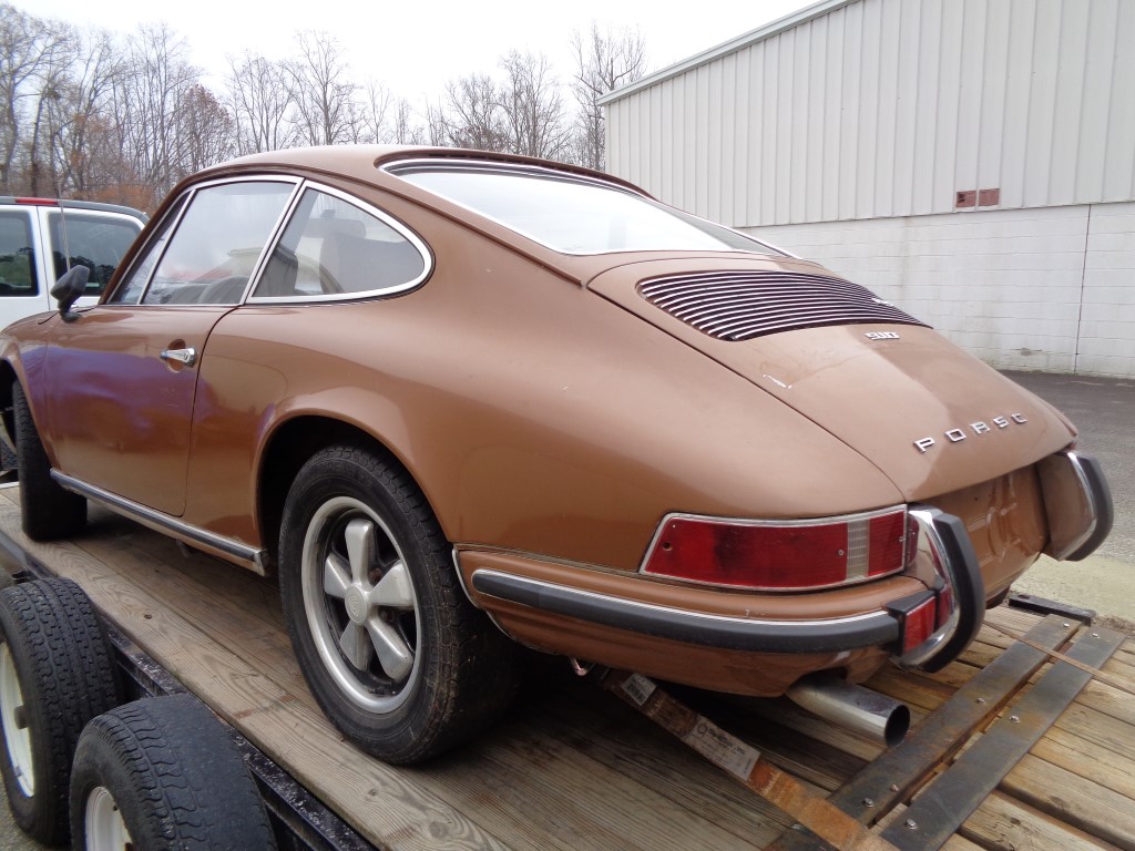
|
|
|
|
| Bulldog9 |
Dec 13 2014, 09:45 PM
Post
#163
|
|
Senior Member Group: Members Posts: 706 Joined: 21-August 13 From: United States Member No.: 16,283 Region Association: MidAtlantic Region |
Assembled the short block today, everything went very smooth, no real issues or surprises. I reweighed the connecting rods and re cleaned everything. 3 weigh in at 813g, 1 at 812g, 3 of my piston sets are 503grams, and 1 is 504. Pretty impressed with the bearing fit and quality. Only had to file a bit on one of the cam bearings. the rest fit perfectly. I pretty much followed the 'conventional wisdom' found on the boards, with a few minor adjustments. Motor spins freely with even resistance, no 'hotspots' The silverline bearings fit perfect.
Attached thumbnail(s) 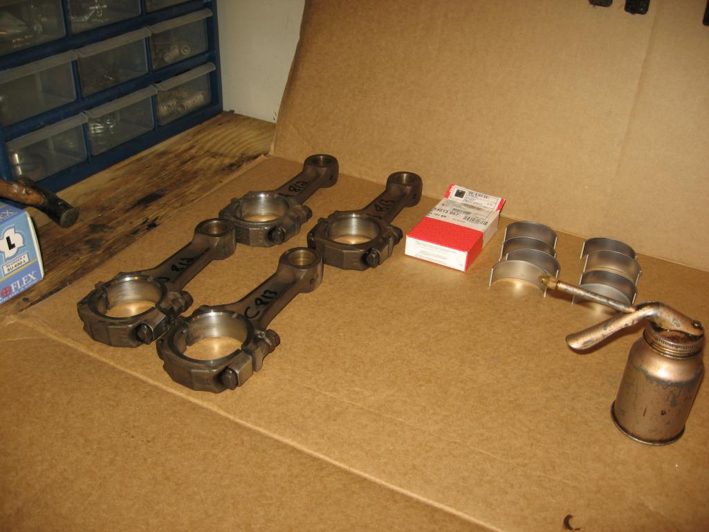 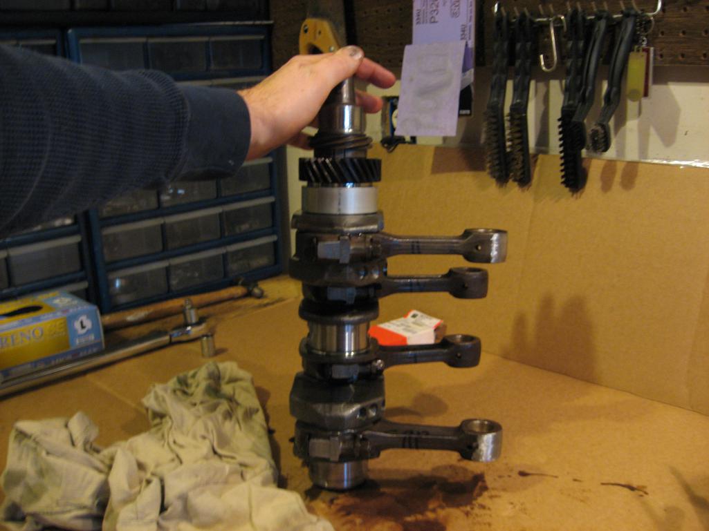 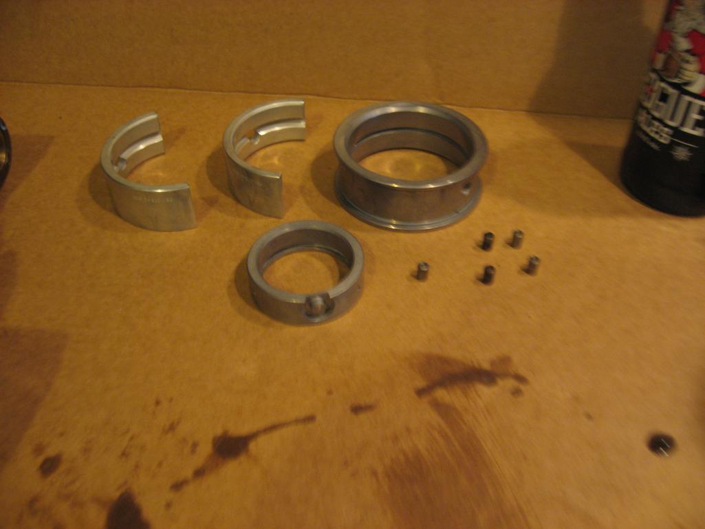
|
|
|
|
| Bulldog9 |
Dec 13 2014, 09:48 PM
Post
#164
|
|
Senior Member Group: Members Posts: 706 Joined: 21-August 13 From: United States Member No.: 16,283 Region Association: MidAtlantic Region |
Took my time and double checked the cam bolts and oil pump clearance, all was great. Jorge at EMW really set me up for success here. I decided to use the windage tray, used a set of needle nose pliers and opened up the slots a bit but left it alone otherwise.
The most excitement of the day involved the cam. After I lined the cam and crank gear dots, I spun the crank to make sure cam lobes and crank and case played well together. In so doing, I put things 180 degrees out of sync. Was an easy fix, just pulled the dist & gear and rotated 180 back, and all was good. Of course lots of 'is it clean enough' thoughts, but all in all it went well. Attached thumbnail(s) 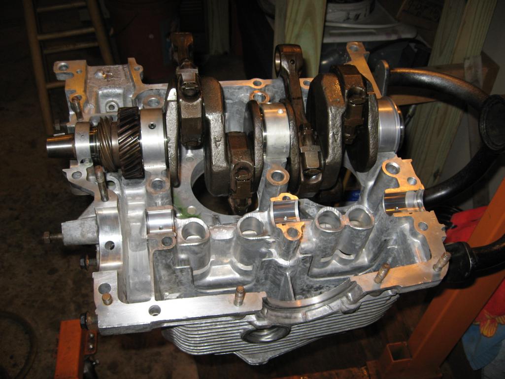 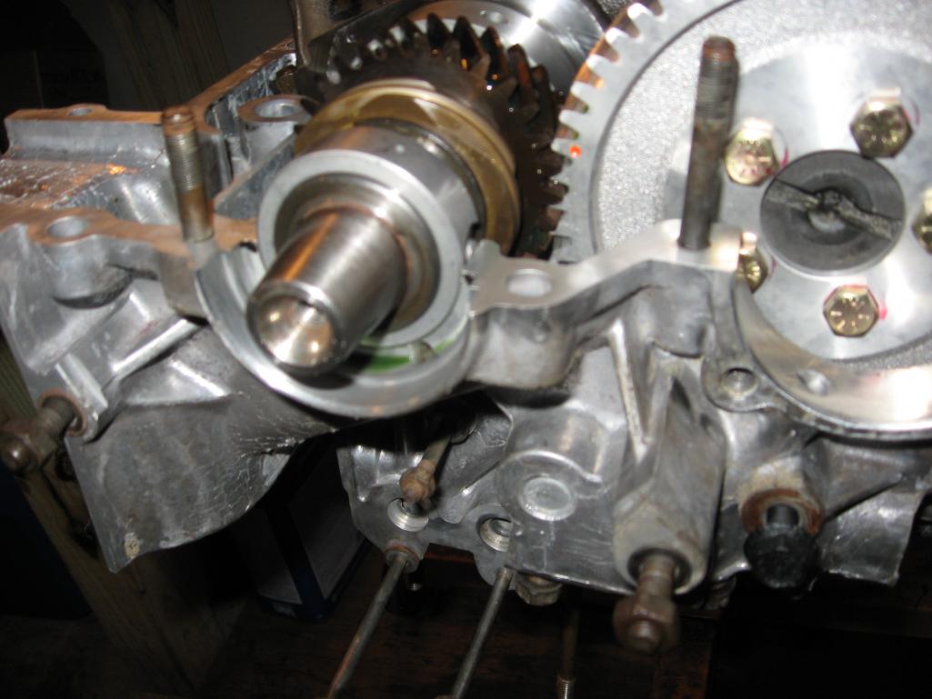 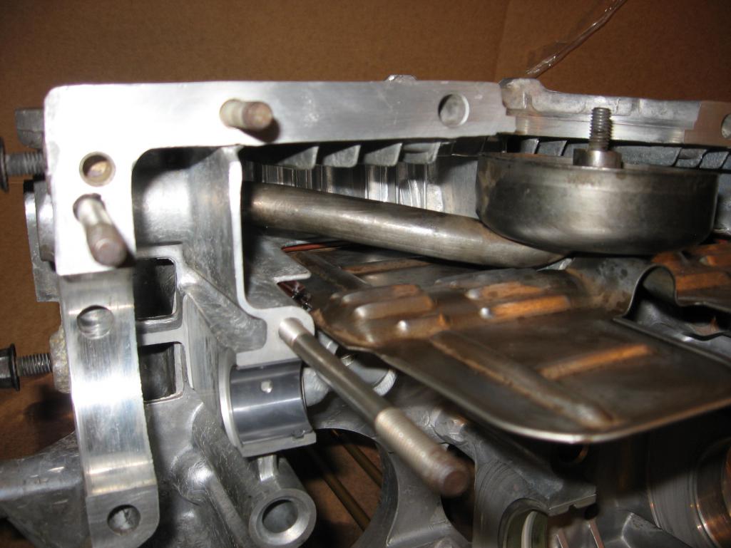 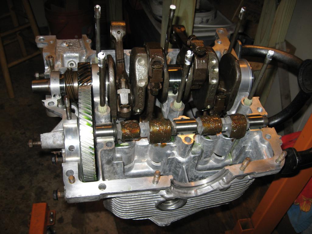
|
|
|
|
| Bulldog9 |
Dec 13 2014, 09:51 PM
Post
#165
|
|
Senior Member Group: Members Posts: 706 Joined: 21-August 13 From: United States Member No.: 16,283 Region Association: MidAtlantic Region |
Finished product
Attached thumbnail(s) 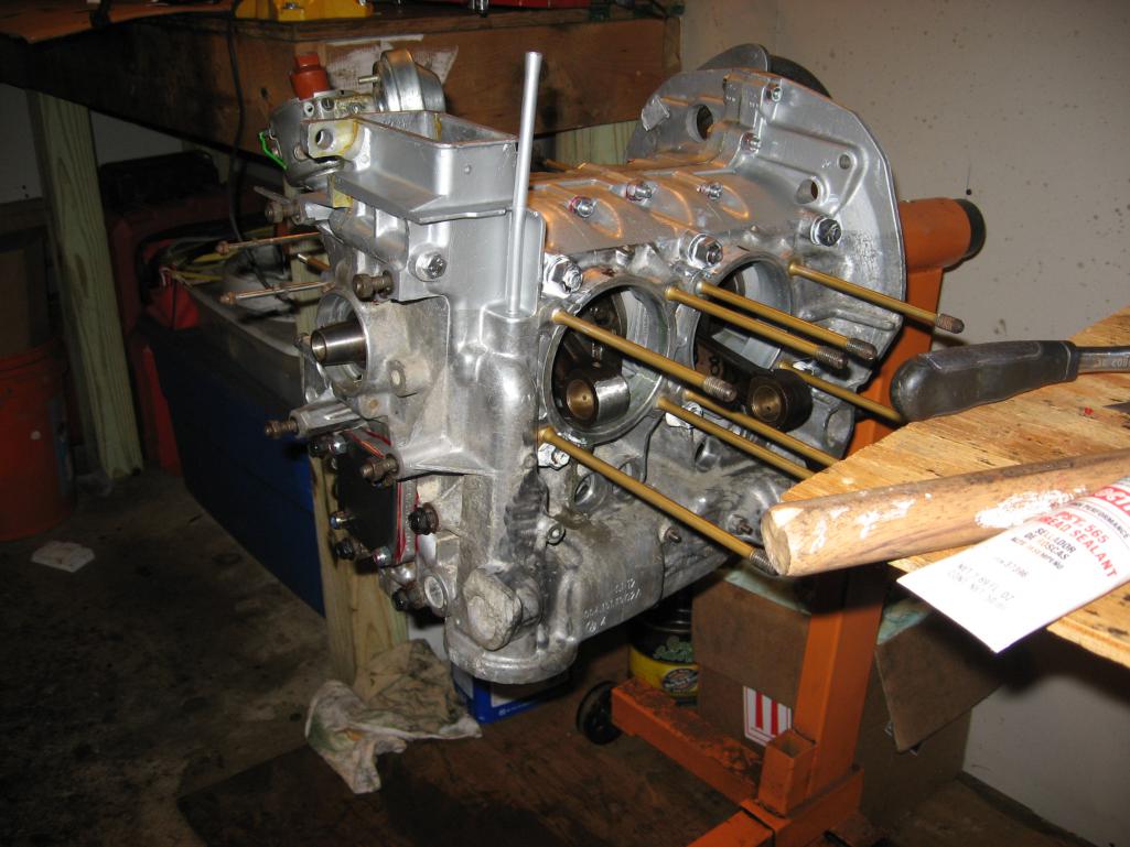 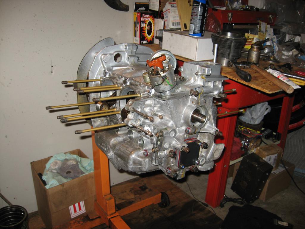
|
|
|
|
| scotty b |
Dec 20 2014, 07:21 PM
Post
#166
|
|
rust free you say ? Group: Members Posts: 16,375 Joined: 7-January 05 From: richmond, Va. Member No.: 3,419 Region Association: None |
SOooooo I ended up repainting the whole car. (IMG:style_emoticons/default/dry.gif) I didn't notice it initially but I had a lot fo tiny white specks in the paint. I had this happen once before and it turned out that the pigment had been sitting on the shelf long enough it had separated and started to harden. I am assuming it was the same thing this time as well. Anyway, here she is almost ready to go home. This time around I got PPG Deltron, and instead of 9 coats to get coverage it took 3 (IMG:style_emoticons/default/dry.gif)
Attached image(s) 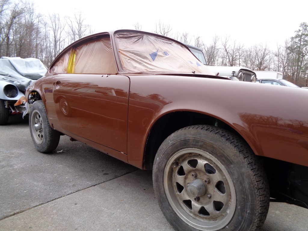 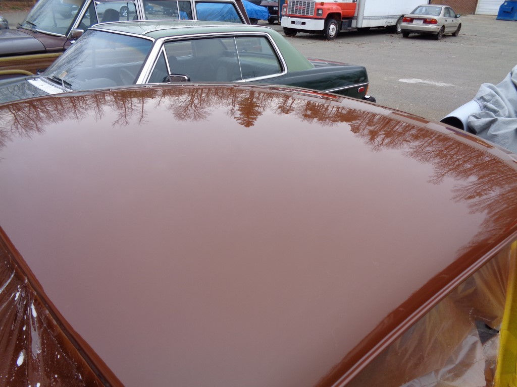 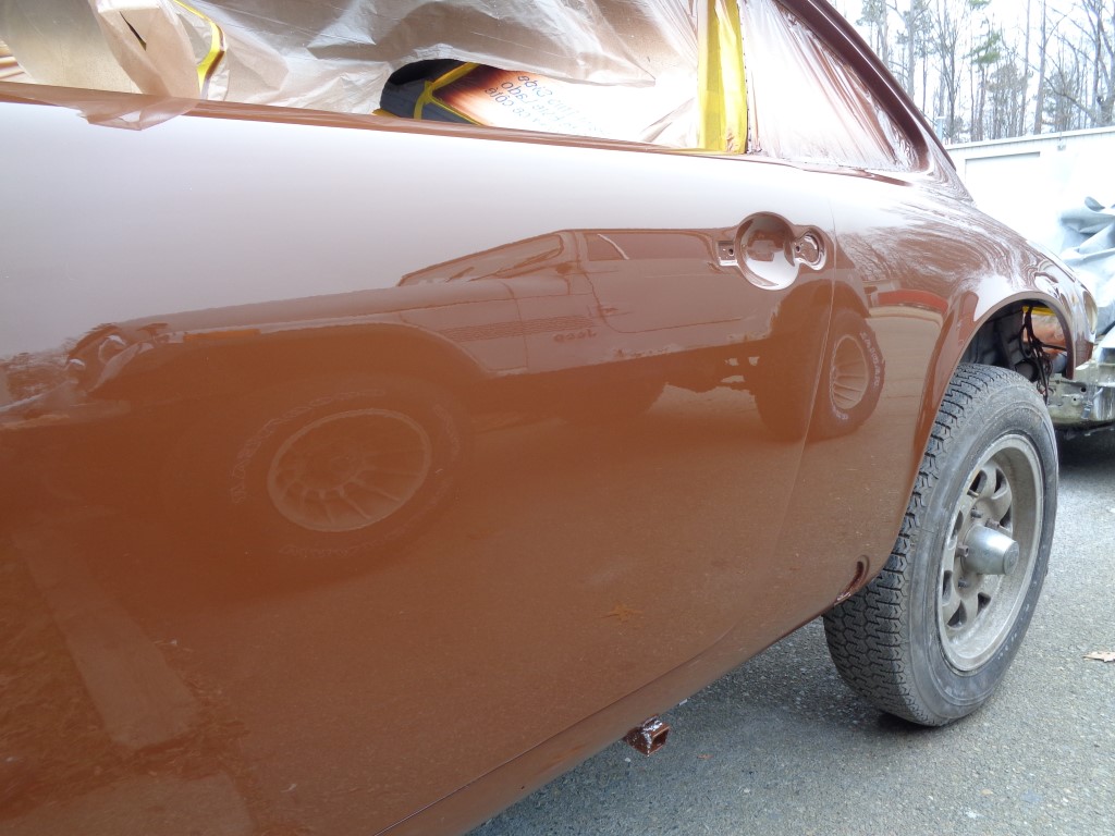 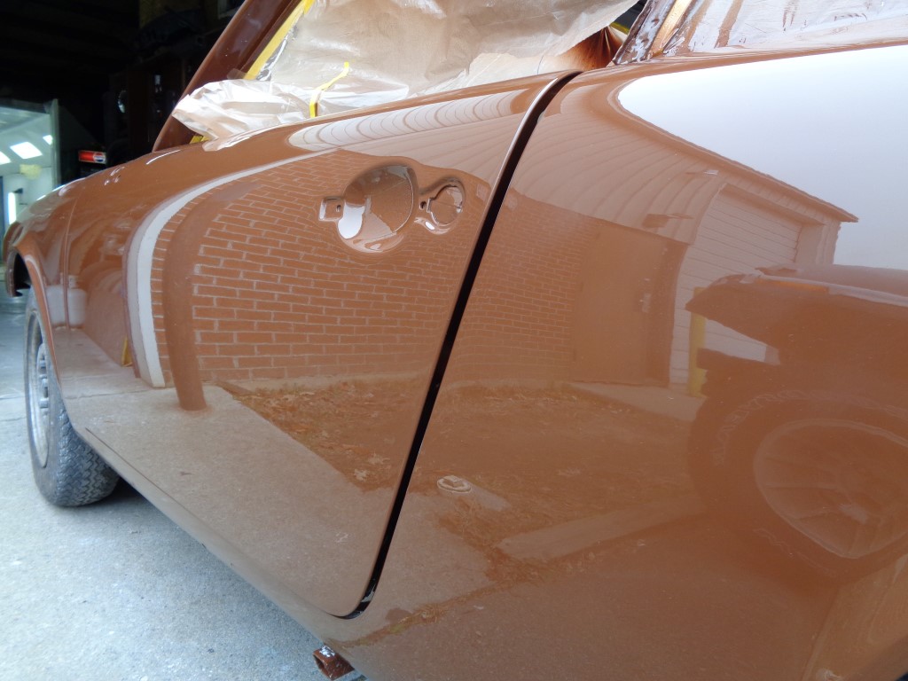 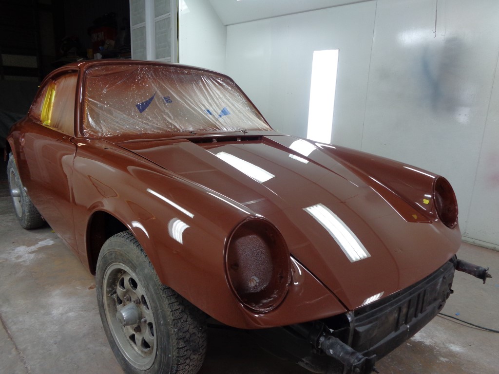 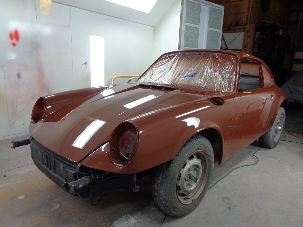
|
|
|
|
| euro911 |
Dec 21 2014, 01:28 AM
Post
#167
|
|
Retired & living the dream. God help me if I wake up! Group: Members Posts: 8,937 Joined: 2-December 06 From: So.Cal. & No.AZ (USA) Member No.: 7,300 Region Association: Southern California |
|
|
|
|
| altitude411 |
Dec 21 2014, 01:43 AM
Post
#168
|
|
I drove my 6 into a tree Group: Members Posts: 1,306 Joined: 21-September 14 From: montana Member No.: 17,932 Region Association: Rocky Mountains |
bitchin....
Attached image(s) 
|
|
|
|
| Bulldog9 |
Dec 21 2014, 03:02 PM
Post
#169
|
|
Senior Member Group: Members Posts: 706 Joined: 21-August 13 From: United States Member No.: 16,283 Region Association: MidAtlantic Region |
(IMG:style_emoticons/default/blink.gif) is it real? (IMG:style_emoticons/default/w00t.gif)
(IMG:style_emoticons/default/pray.gif) looks great! |
|
|
|
| scotty b |
Dec 21 2014, 05:22 PM
Post
#170
|
|
rust free you say ? Group: Members Posts: 16,375 Joined: 7-January 05 From: richmond, Va. Member No.: 3,419 Region Association: None |
QUOTE(Steve Pratel @ Dec 21 2014, 01:02 PM) (IMG:style_emoticons/default/blink.gif) is it real? (IMG:style_emoticons/default/w00t.gif) (IMG:style_emoticons/default/pray.gif) looks great! Nope......Memorex (IMG:style_emoticons/default/unsure.gif) |
|
|
|
| Bulldog9 |
Dec 21 2014, 05:51 PM
Post
#171
|
|
Senior Member Group: Members Posts: 706 Joined: 21-August 13 From: United States Member No.: 16,283 Region Association: MidAtlantic Region |
More progress on the motor build, spent 2-3 hours last night and 1 hour rechecking today and came up with 27.09 as my final measurement. Virtually stock......
This will give me a total lift of .437 at the valve on a .430 lift cam, and about perfect alignment of the valve stem and adjuster with some room for adjustment on the swivel head and acceptable spring compression at full lift. Overall I am happy. A few thoughts...... Its not that big of a deal..... overall lift diddnt change much regardless of pushrod/adjuster, what really changed was the ALIGNMENT of the valve stem and adjuster at half lift. I had to make significant adjustments for this, and diddnt really change overal llift at valve, maybe .5mm. Once I finished, I re-lubed the cam with the assembly grease, and dissasembled the head and cyls. As I stated before, I just slipped the pistons on teh con rods and ran in cyls without rings. This allowed guaranteed TDC and c rod slap inside the cyls. I did this on cyls 1 & 2, and came up with slightly different figures (a bit more lift on cyl 1, but within the recommended 5%) Now on to the pistons & cyls. Am using an EMW G cam (430LIFT), lubealobe LIfters, OEM 911 swivel foot adjusters. Rocker Zero Lift 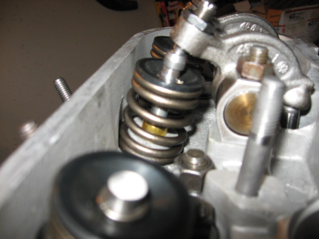 Half Lift 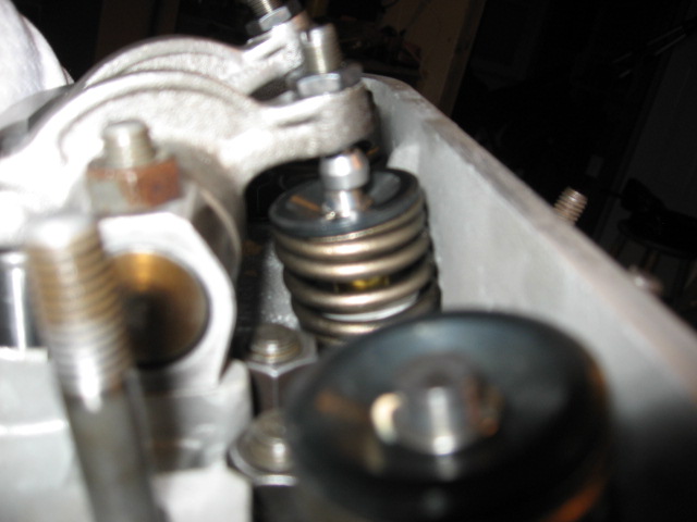 Full Lift 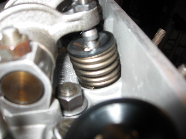 Finished Pushrod 27.09 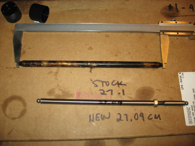 |
|
|
|
| Bulldog9 |
Dec 21 2014, 07:06 PM
Post
#172
|
|
Senior Member Group: Members Posts: 706 Joined: 21-August 13 From: United States Member No.: 16,283 Region Association: MidAtlantic Region |
Moving on to Pistons & Cyls.
As this is my first time doing any of this, I am in measure 4X mode and double/triple check as I go. I had earlier weighed and matched the pistons and con rods, so now that it is time to assemble, after cleaning everything well, oiling the interior of the cyls, I started laying everything out. I weighed and marked each Con rod as well and matched them to the pistons by weight to be equal within .07 grams. I also had the crank, fan and flywheel balanced, so hopefully this will end in a very balanced motor. 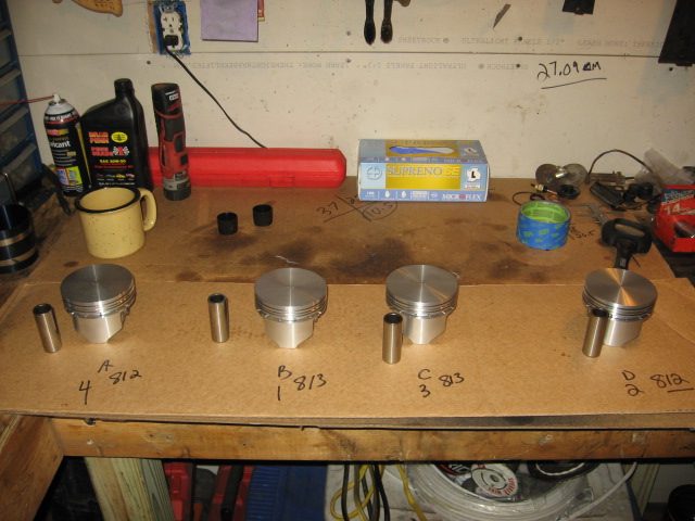 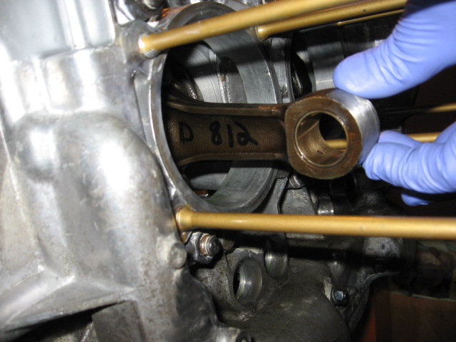 After cleaning I taped and sprayed a light coat of high heat black on the cyls. 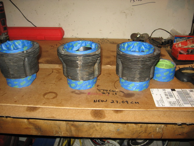 One of the things about the KB pistons is they are not directional, meaning there is no arrow. That said, there is a STD mark on each piston and I decided to orient things so that the STD's will be facing up in the motor. 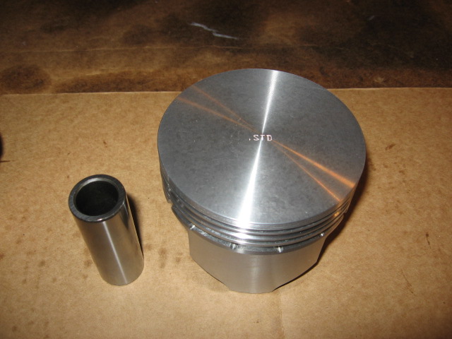 This is my first time using Spirolocks, and while they take some getting used to, they look bulletproof. I found opening them about 1/2 inch and to 'thread' it into the spirolock slot in the piston was a great way to get started, otherwise when you try to press the ring into the slot it kept slipping out. Because you need to install once side of the spirolocks before attaching to motor, and I determined my pistons would all face the same way, I had to be particular about what side I put them on. I will probably go in order 4, 3, 2, 1. 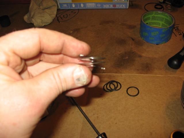 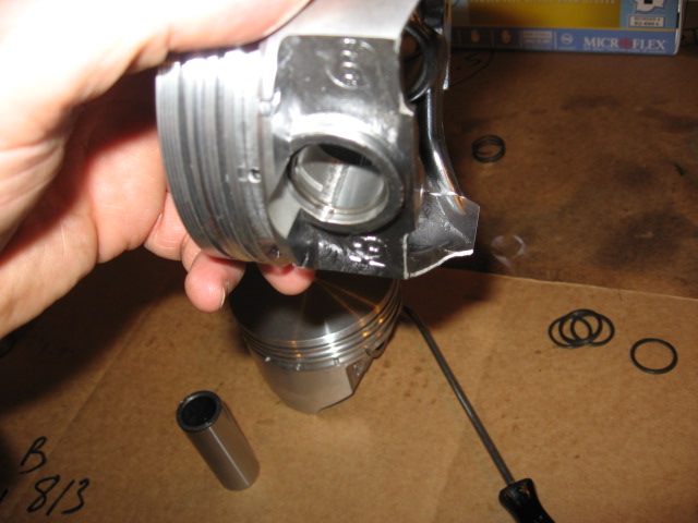 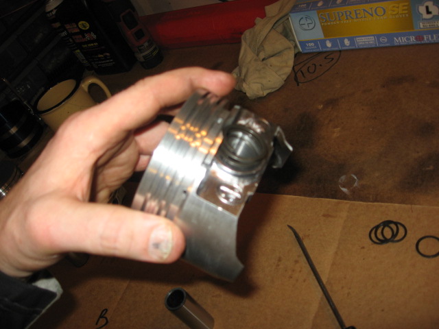 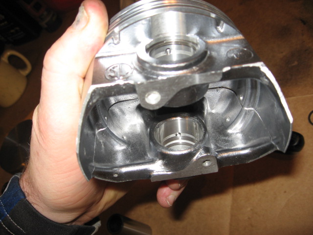 I also thought I would post a picture of a tool that has been INVALUABLE over the last 20 years. I originally accidentally bent this screwdriver back in the late 80's, and it has saved my butt more times than I can count. Happy accidents! 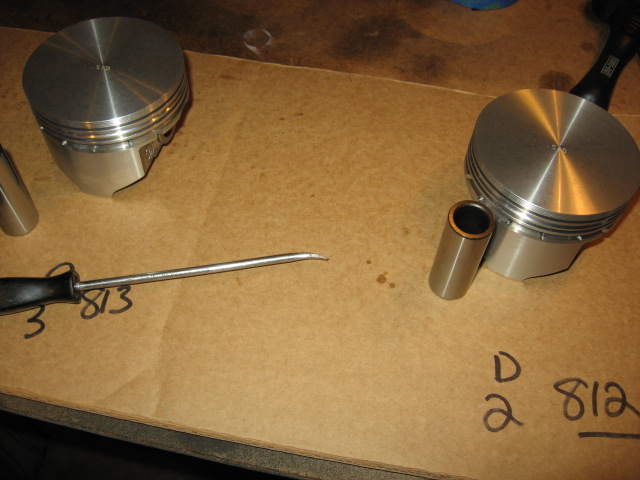 Overall the KB pistons are works of art. Top notch quality, very impressive. Floating writs pins are also a plus. Attached image(s) 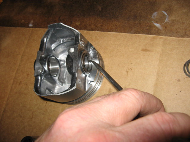
|
|
|
|
| Bulldog9 |
Dec 21 2014, 08:24 PM
Post
#173
|
|
Senior Member Group: Members Posts: 706 Joined: 21-August 13 From: United States Member No.: 16,283 Region Association: MidAtlantic Region |
Of course all good things come to an end..... After measuring the ring gaps and adjusting so all were the same, I cleaned them up and started installing. The 2nd compression ring has a dot that must face up and of course I made sure it was..... I wish. I realized what I did, and when I tried to pull it out, in an attempt to not mar the side of the piston, I pulled just a little too far and it snapped..........
So I went on, it was for piston #1, so I figured I'd go to #4, and work my way down, get 4, 3 & 2 installed and then #1 when I got the extra ring, but unfortunately, my cheap @$$ ring compressor sucks..... Wouldn't compress the oil scrapers enough to insert into the cyl. grrrr. It was interesting to see the difference in ring gaps when uncompressed. 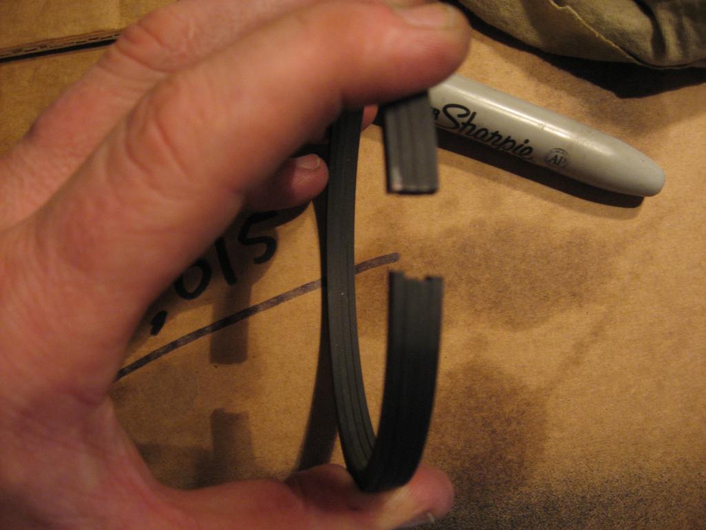 The compressed measurements, ranged from .18 - .20. I initially wrote .22 but it was actually .20 as the gap wasn't even, it was angled .22 in the inside and .20 at the outside. 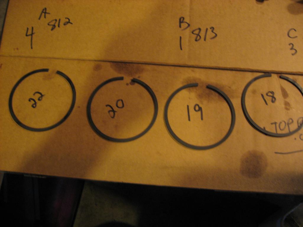 The Top ring gaps are now all at .20, and even, not angled. The Second ring is a uniform .15 and was not angled. It almost seems as though the top ring set was resized/modified? I need to ask EMW about this. If so, was pretty shoddy work. KB recommends opening the top ring gap by .10, Len Hoffman says leave stock, and Raby says leave as is, so I'm guessing going from teh stock .15 to .20 is a met in the middle compromise. Most important to me is that the gap is even. 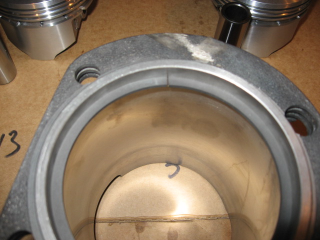 And the broken ring............... Can I just buy ONE? or do I have to buy the whole set? Things are busy before Christmas, but I will run to Napa tomorrow to check on the ring/ringset and to pickup a real ring compressor, and drop the pushrods off at the machine shop to cut and assemble the pushrods. Hmmm, the Gun range is right next to the Napa...... Yeah I need some trigger time.... Gotta stay fresh on the conceal carry skills. (IMG:style_emoticons/default/ar15.gif) 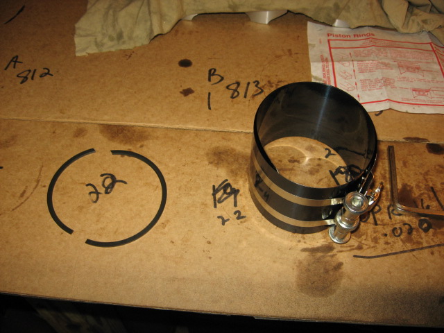 |
|
|
|
| Bulldog9 |
Dec 21 2014, 08:56 PM
Post
#174
|
|
Senior Member Group: Members Posts: 706 Joined: 21-August 13 From: United States Member No.: 16,283 Region Association: MidAtlantic Region |
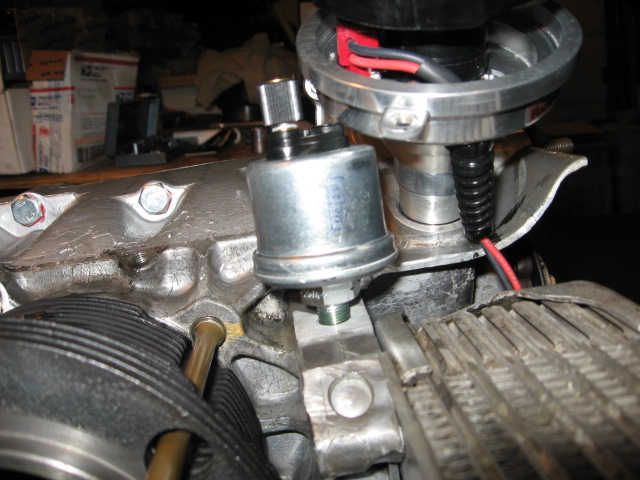
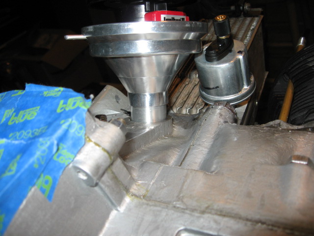
Once my plan to set pistons and cyls was kaboshed, I decided to finish altering the cooling tin for use with my 911 pressure gauge and the Pertronix Billet distributor.
The Pertronix Dist is MUCH larger in diameter than the stock Bosch. I used a ball peen hammer and slowly shaped a divot in the cooling tin for the distributor. The result is about a 1/8" gap between the tin and spark plug wire boot. Even with the modification, I have to take the cap off the distributor, mount the distributor and then cap, but it fits well. 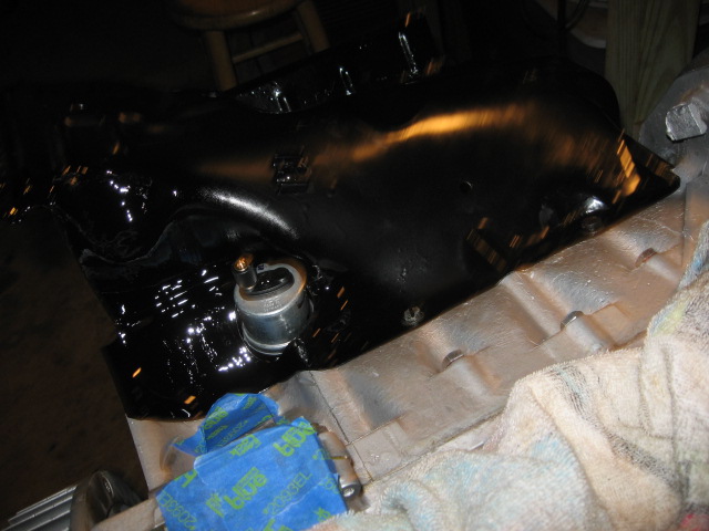 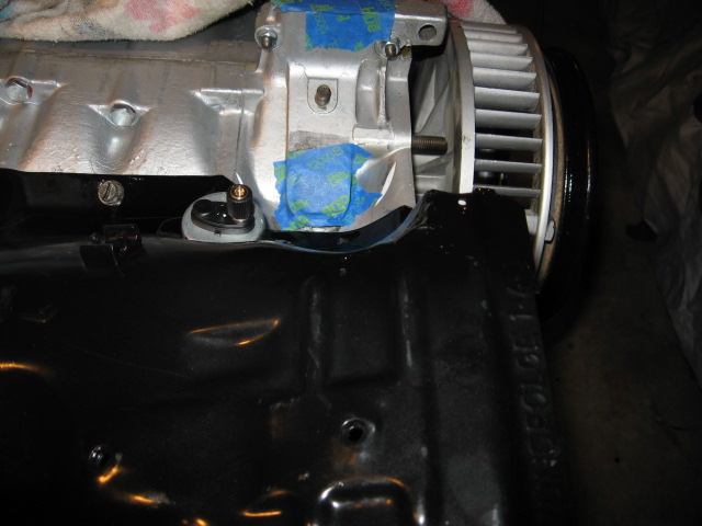 I also had to open up the oil pressure sender.to fit the 911 style oil pressure sender. I'm using a 911 pressure/temp gauge as opposed to an idiot light. I was planning on using a t block to run a pressure switch for the idiot light too, but It doesnt look like it will fit with the oil cooler and cyl in place. Jury is still out on this. At a minimum, I will run the temp & pressure gauges. 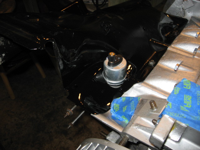 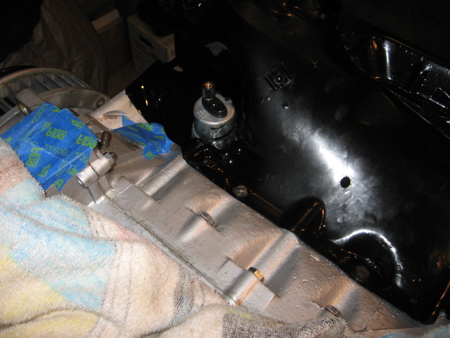 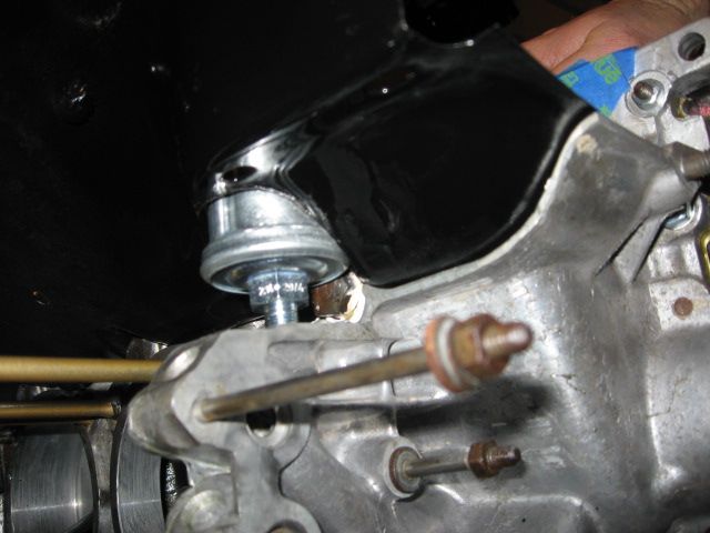 |
|
|
|
| Bulldog9 |
Dec 22 2014, 09:35 PM
Post
#175
|
|
Senior Member Group: Members Posts: 706 Joined: 21-August 13 From: United States Member No.: 16,283 Region Association: MidAtlantic Region |
3 Steps forward? 2 steps back..... Yesterday I finished sizing the engine tin for the oil pressure sensor and Larger Distributor. Everything fit individually, and looked good. But as I looked at the oil pressure sensor, it looked a bit high so I decided to check and see clearance for the Pertronix, and sure enough it is too tall. I had bought the pressure switch for idiot light and the sender for the gauge, but was having clearance problems so I decided to skip the idiot light sender (I dont need no stinking idiot light (IMG:style_emoticons/default/shades.gif) ).
  Yeah that wont work...... So this sent me to the local hardware store for some 1/8" brass..... Ended up with this. Is a bit of a goat rope, and hoping that this will work. What do you guys think? I will have to assemble in sections, but this arrangement allows both pressure sender and switch, and allows full rotation of distributor. Here is the finished product 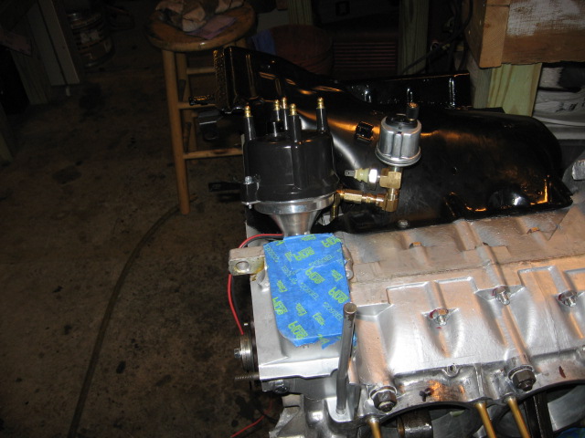 Working backwards without distributor 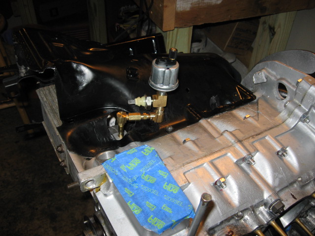 Then without the pressure switch 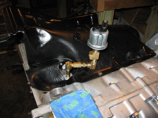 Then the splitter and pressure sensor 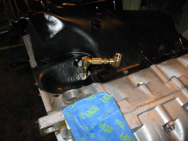 And finally the extension, leaving only the one 1 1/2" stub and elbow 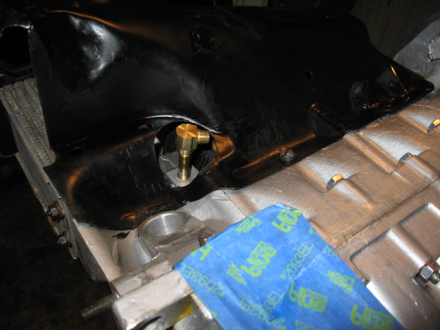 Yes, I am asking myself WHAT DID YOU GET YOURSELF INTO............... OY (IMG:style_emoticons/default/WTF.gif) It looks better in real life than in pics.... But hey everybody has to have a little ghetto on their build right? lol I'm hoping that the 2 elbows will not be a problem with oil pressure, will I need to bleed this contraption? And of course I am thinking what fun I will have when I try to do the carb linkage.......... And of course after I ground that big hole for the sender to poke through the tin......... (IMG:style_emoticons/default/chair.gif) |
|
|
|
| ChrisFoley |
Dec 23 2014, 07:24 AM
Post
#176
|
|
I am Tangerine Racing Group: Members Posts: 8,024 Joined: 29-January 03 From: Bolton, CT Member No.: 209 Region Association: None |
You should switch that brass assembly for a hose Steve.
|
|
|
|
| Cairo94507 |
Dec 23 2014, 07:54 AM
Post
#177
|
|
Michael Group: Members Posts: 10,638 Joined: 1-November 08 From: Auburn, CA Member No.: 9,712 Region Association: Northern California |
Great story and build thread. The paint looks terrific. My first 914 was a '73 2.0 appearance group in Sepia Brown - definitely lighter in color than the chocolate. The color grows on you for sure.
|
|
|
|
| Bulldog9 |
Dec 23 2014, 10:31 AM
Post
#178
|
|
Senior Member Group: Members Posts: 706 Joined: 21-August 13 From: United States Member No.: 16,283 Region Association: MidAtlantic Region |
QUOTE(Racer Chris @ Dec 23 2014, 08:24 AM) You should switch that brass assembly for a hose Steve. Yeah, I was thinking about that and the possibility of leaning on the unit and cracking the boss..... Is such a line available? or should I do barbed fittings and clamps on oil line? |
|
|
|
| Dave_Darling |
Dec 23 2014, 11:45 PM
Post
#179
|
|
914 Idiot Group: Members Posts: 15,339 Joined: 9-January 03 From: Silicon Valley / Kailua-Kona Member No.: 121 Region Association: Northern California |
Check around; there may still be adapter kits available. I have heard of people using a grease gun hose and some adapters as well.
The pipe creation is going to put a lot more stress on the mounting boss. Bad idea IMHO. --DD |
|
|
|
| ChrisFoley |
Dec 24 2014, 07:08 AM
Post
#180
|
|
I am Tangerine Racing Group: Members Posts: 8,024 Joined: 29-January 03 From: Bolton, CT Member No.: 209 Region Association: None |
QUOTE(Dave_Darling @ Dec 24 2014, 12:45 AM) Check around; there may still be adapter kits available. I have heard of people using a grease gun hose and some adapters as well. The pipe creation is going to put a lot more stress on the mounting boss. Bad idea IMHO. --DD I recommend against grease gun hoses and paintball gun hoses. The rubber in them isn't designed for the chemical/temperature environment. We're starting to make our own hoses from Aeroquip parts. Someone suggested a brake hose but I haven't seen that in usage yet, and I'm not sure about availability of the proper adapter fittings. |
|
|
|
|
1 User(s) are reading this topic (1 Guests and 0 Anonymous Users)
0 Members:

|
Lo-Fi Version | Time is now: 23rd May 2026 - 01:01 PM |
Invision Power Board
v9.1.4 © 2026 IPS, Inc.