|
|
|
Porsche, and the Porsche crest are registered trademarks of Dr. Ing. h.c. F. Porsche AG.
This site is not affiliated with Porsche in any way. Its only purpose is to provide an online forum for car enthusiasts. All other trademarks are property of their respective owners. |
|
|

  |

| HalfMoon |
 Aug 27 2013, 03:52 PM Aug 27 2013, 03:52 PM
Post
#1
|
|
Senior Member  Group: Members Posts: 828 Joined: 13-November 12 From: Shenandoah Junction, WV Member No.: 15,144 Region Association: MidAtlantic Region |
Imagine my dismay when today I decided to open the dash (I was trouble shooting a fuel gauge not working-easy fix, PO had cut the wires at the tank for some reason), discovering a huge amount of loose wires. The PO had installed a completly different tach so I'm hoping alot of these wires (11) had a purpose for being disconnected. Vain hope most likely...
I did notice the brake warning light stays on all the time...and of course nothing else works (except the fuel gauge that I just hooked back up). The car is a v-8 converted teener so alot of stuff may be disconnected for that reason as well. The real problem is that I'm VERY color blind. I can read a schematic reasonably well if I know what color wires I'm looking at on the car, which brings us to the reason for this post! Could someone help me identify the loose wires I've numbered in the enclosed photograph? What color corresponds to the numbered wires? With that data I should be able to figure out what was supposed to go where and assimilate if it was disconnected for purpose. Wiring and color blindness can be a serious challenge, so any help is appreciated :-) David Oh and btw, if you click on the image and then click again you'll get a very close view 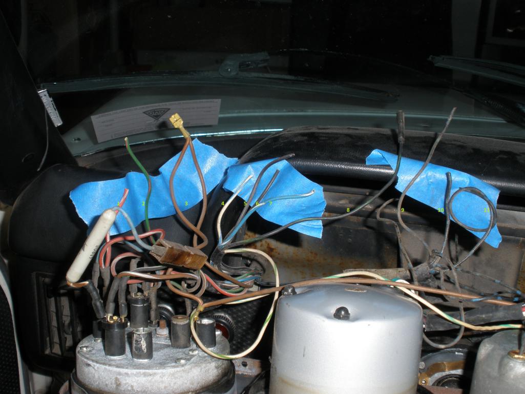 |
   |

 
|
| Ferg |
Aug 27 2013, 03:57 PM
Post
#2
|
|
914 Guru Group: Members Posts: 5,948 Joined: 8-January 03 From: Boulder CO Member No.: 116 Region Association: None |
1. Red/white stripe
2. Green/red stripe 3. Brown 4. White/blue stripe 5. Black 6. Black (maybe white stripe against blue tape?) 7. Blue/white stripe 8. Black/green stripe 9. Black/blue stripe 10.Black/blue stripe 11.Black/blue stripe |
|
|
|
| HalfMoon |
Aug 27 2013, 04:03 PM
Post
#3
|
|
Senior Member Group: Members Posts: 828 Joined: 13-November 12 From: Shenandoah Junction, WV Member No.: 15,144 Region Association: MidAtlantic Region |
(IMG:style_emoticons/default/headbang.gif)
QUOTE(Ferg @ Aug 27 2013, 05:57 PM)  1. Red/white stripe 2. Green/red stripe 3. Brown 4. White/blue stripe 5. Black 6. Black (maybe white stripe against blue tape?) 7. Blue/white stripe 8. Black/green stripe 9. Black/blue stripe 10.Black/blue stripe 11.Black/blue stripe Thank you very much! Now to bury my face in Haynes! (IMG:style_emoticons/default/headbang.gif) |
|
|
|
| bulitt |
Aug 27 2013, 04:05 PM
Post
#4
|
|
Achtzylinder Group: Members Posts: 4,188 Joined: 2-October 11 Member No.: 13,632 Region Association: South East States |
|
|
|
|
| HalfMoon |
Aug 27 2013, 04:35 PM
Post
#5
|
|
Senior Member Group: Members Posts: 828 Joined: 13-November 12 From: Shenandoah Junction, WV Member No.: 15,144 Region Association: MidAtlantic Region |
QUOTE(bulitt @ Aug 27 2013, 06:05 PM) HUGE help (IMG:style_emoticons/default/piratenanner.gif) Although it appears to be for some other year than a 1973... |
|
|
|
| JeffBowlsby |
Aug 27 2013, 05:12 PM
Post
#6
|
|
914 Wiring Harnesses Group: Members Posts: 8,479 Joined: 7-January 03 From: San Ramon CA Member No.: 104 Region Association: None |
That diagram is for 1974 car... (IMG:style_emoticons/default/wink.gif)
But it should still be somewhat useful if not entirely accurate. The wire colors/stripes should indicate what each goes to per the tabel at the bottom. The 1973 car has that diode in the circuits for the combo brake warning (master cyl)/ebrake light. The factory schematics will tell you where each wire goes - I think Pelican has them online. |
 |
|
| HalfMoon |
Aug 27 2013, 07:03 PM
Post
#7
|
|
Senior Member Group: Members Posts: 828 Joined: 13-November 12 From: Shenandoah Junction, WV Member No.: 15,144 Region Association: MidAtlantic Region |
QUOTE(Jeff Bowlsby @ Aug 27 2013, 07:12 PM) That diagram is for 1974 car... (IMG:style_emoticons/default/wink.gif) But it should still be somewhat useful if not entirely accurate. The wire colors/stripes should indicate what each goes to per the tabel at the bottom. The 1973 car has that diode in the circuits for the combo brake warning (master cyl)/ebrake light. The factory schematics will tell you where each wire goes - I think Pelican has them online. Jeff, Is it the one enclosed? On the legend I'm not exactly sure of what I'm seeing :-( The "combo", are they referring to 41 Diode on chart C, legend D? I see the speedo and tach on Chart A, Legend B but nothing that looks like the combo gauge :-/ Cornfused. 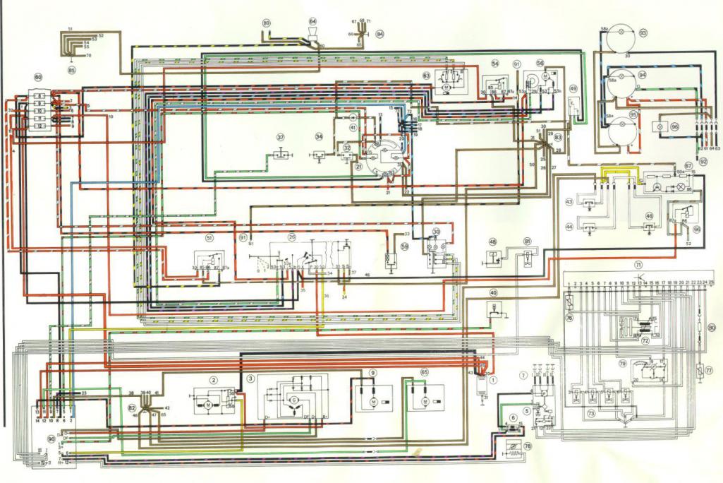 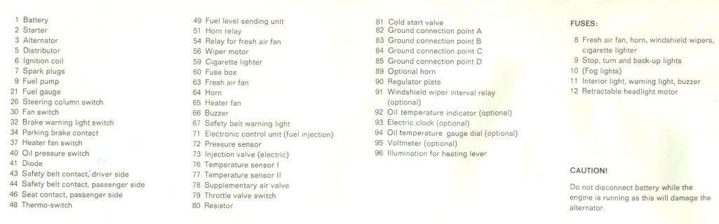 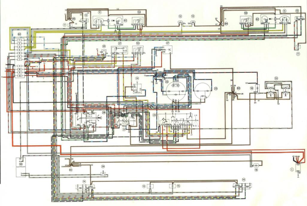 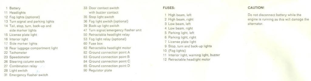 |
|
|
|
| bulitt |
Aug 28 2013, 06:54 AM
Post
#8
|
|
Achtzylinder Group: Members Posts: 4,188 Joined: 2-October 11 Member No.: 13,632 Region Association: South East States |
Moonman- I happened to label the back of my cluster on my 73. Couldn't recall I did it, oldsheisers.
So here is a pic. 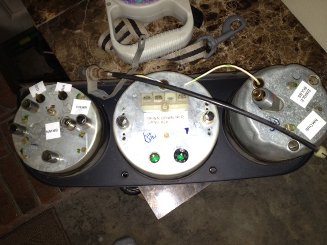 On the speedo the wire coming out the bottom is white/green -------- On the tach the wires from left to right are- brown brown/black red and the wire coming out of the bottom of the tach is white/blue ----------- On the combo clockwise in pic from 1100pm red green brown the rest of your wires you should be able to determine from Jeffs diagram- black/blue=gauge lights |
|
|
|
| JeffBowlsby |
Aug 28 2013, 07:49 AM
Post
#9
|
|
914 Wiring Harnesses Group: Members Posts: 8,479 Joined: 7-January 03 From: San Ramon CA Member No.: 104 Region Association: None |
QUOTE(HalfMoon @ Aug 27 2013, 06:03 PM) QUOTE(Jeff Bowlsby @ Aug 27 2013, 07:12 PM) That diagram is for 1974 car... (IMG:style_emoticons/default/wink.gif) But it should still be somewhat useful if not entirely accurate. The wire colors/stripes should indicate what each goes to per the tabel at the bottom. The 1973 car has that diode in the circuits for the combo brake warning (master cyl)/ebrake light. The factory schematics will tell you where each wire goes - I think Pelican has them online. Jeff, Is it the one enclosed? On the legend I'm not exactly sure of what I'm seeing :-( The "combo", are they referring to 41 Diode on chart C, legend D? I see the speedo and tach on Chart A, Legend B but nothing that looks like the combo gauge :-/ Cornfused. Looks right to me...21 is the combo gauge. |
|
|
|
| Dave_Darling |
Aug 28 2013, 08:04 AM
Post
#10
|
|
914 Idiot Group: Members Posts: 14,981 Joined: 9-January 03 From: Silicon Valley / Kailua-Kona Member No.: 121 Region Association: Northern California |
Note that the wires numbered 9, 10, and 11 are add-ons by some previous owner or previous mechanic. They have blue stripes around the wire, rather than a blue tracer painted along the wire. Painting rings around the wire is easier to do for most of us than the factory-style line along the wire.
Since someone did take the trouble to paint blue on those wires, it is very highly likely that they are connected to the gauge illumination circuit. --DD |
|
|
|
| HalfMoon |
Aug 28 2013, 08:29 AM
Post
#11
|
|
Senior Member Group: Members Posts: 828 Joined: 13-November 12 From: Shenandoah Junction, WV Member No.: 15,144 Region Association: MidAtlantic Region |
QUOTE(Dave_Darling @ Aug 28 2013, 10:04 AM) Note that the wires numbered 9, 10, and 11 are add-ons by some previous owner or previous mechanic. They have blue stripes around the wire, rather than a blue tracer painted along the wire. Painting rings around the wire is easier to do for most of us than the factory-style line along the wire. Since someone did take the trouble to paint blue on those wires, it is very highly likely that they are connected to the gauge illumination circuit. --DD Oh that's very informative! I had no idea. The gauge cluster is unlit and I had thought (according to Jeff's handy chart for a 1974) that these were all for illumination. Now I'm not so sure....but easy enough to test when I go out to the garage today. Thanks DD |
|
|
|
| HalfMoon |
Aug 28 2013, 08:34 AM
Post
#12
|
|
Senior Member Group: Members Posts: 828 Joined: 13-November 12 From: Shenandoah Junction, WV Member No.: 15,144 Region Association: MidAtlantic Region |
QUOTE(bulitt @ Aug 28 2013, 08:54 AM) Moonman- I happened to label the back of my cluster on my 73. Couldn't recall I did it, oldsheisers. So here is a pic. On the speedo the wire coming out the bottom is white/green -------- On the tach the wires from left to right are- brown brown/black red and the wire coming out of the bottom of the tach is white/blue ----------- On the combo clockwise in pic from 1100pm red green brown the rest of your wires you should be able to determine from Jeffs diagram- black/blue=gauge lights Extremely helpful! (IMG:style_emoticons/default/beer.gif) |
|
|
|
| JeffBowlsby |
Aug 28 2013, 10:09 AM
Post
#13
|
|
914 Wiring Harnesses Group: Members Posts: 8,479 Joined: 7-January 03 From: San Ramon CA Member No.: 104 Region Association: None |
Actually...
The factory used different striping patterns over the years. Early cars through 1973 have at least some of the wires where the 'stripes' are circumferential. Later cars, the stripes run longitudinally along the length of the wire. And I have found the different striping patterns intermixed on the same harness...maybe a mix of suppliers or striping equipment? The color coding was similar though - brown is always ground. Black/blue is typically illumination. Each gauge component has its own color code - see the schedule above as a guide. |
|
|
|
| HalfMoon |
Aug 28 2013, 10:28 AM
Post
#14
|
|
Senior Member Group: Members Posts: 828 Joined: 13-November 12 From: Shenandoah Junction, WV Member No.: 15,144 Region Association: MidAtlantic Region |
QUOTE(Jeff Bowlsby @ Aug 28 2013, 12:09 PM) Actually... The factory used different striping patterns over the years. Early cars through 1973 have at least some of the wires where the 'stripes' are circumferential. Later cars, the stripes run longitudinally along the length of the wire. And I have found the different striping patterns intermixed on the same harness...maybe a mix of suppliers or striping equipment? The color coding was similar though - brown is always ground. Black/blue is typically illumination. Each gauge component has its own color code - see the schedule above as a guide. Ah, so it's as I suspected, 9,10,11 are most likely illumination. I've managed to get the fuel gauge working, and beyond that the goal was to have gauge illumination, the high beam indicator, flashers and turn signals. The rest (Gen, E brake, brake warning, oil press, fuel reserve, parking light) are things I don't really need. Btw, without ya'lls valuable input I simply could not get this done as I'm severly color blind. I very much appreciate your help. |
|
|
|
| JeffBowlsby |
Aug 28 2013, 01:19 PM
Post
#15
|
|
914 Wiring Harnesses Group: Members Posts: 8,479 Joined: 7-January 03 From: San Ramon CA Member No.: 104 Region Association: None |
This is really sad to see, you are going to have hard time connecting all this up. Someone simply cut off the chassis harness wires to the dash gauges rather than take the 0.2 seconds required to remove the connections. Some of this will require at least soldered spliced-in connections.
NOTHING EVER NEEDS TO BE CUT OFF A WIRING HARNESS, JUST DISCONNECT THINGS! Some of those wires maybe just needs simple crimped-on 1/4 in female wire terminals if teh wires are long enough to reach their gauges, others may need a light socket which can only be clipped off some other harness. |
|
|
|
| bulitt |
Aug 28 2013, 02:47 PM
Post
#16
|
|
Achtzylinder Group: Members Posts: 4,188 Joined: 2-October 11 Member No.: 13,632 Region Association: South East States |
QUOTE(Jeff Bowlsby @ Aug 28 2013, 03:19 PM) This is really sad to see, you are going to have hard time connecting all this up. Someone simply cut off the chassis harness wires to the dash gauges rather than take the 0.2 seconds required to remove the connections. Some of this will require at least soldered spliced-in connections. NOTHING EVER NEEDS TO BE CUT OFF A WIRING HARNESS, JUST DISCONNECT THINGS! Some of those wires maybe just needs simple crimped-on 1/4 in female wire terminals if teh wires are long enough to reach their gauges, others may need a light socket which can only be clipped off some other harness. should be an auto resonse for everyones first post- dont cut any wires, handle rubber seals gently protect your glass (IMG:style_emoticons/default/laugh.gif) |
|
|
|
| HalfMoon |
Aug 28 2013, 05:45 PM
Post
#17
|
|
Senior Member Group: Members Posts: 828 Joined: 13-November 12 From: Shenandoah Junction, WV Member No.: 15,144 Region Association: MidAtlantic Region |
Sigh. Well I goofed around with the pod wires some more today and we were right the wires 9, 10, 11 (from the previous photo's) were indeed illumination. So now I have a fuel gauge and the pods illuminated.
Sadly I simply wasn't able to identify the turn signal wires (using a test light-I did find some that corresponded to the turn signal switch, but once tested, they would continue to flash on the dash even when off). I have at least achieved a working fuel gauge and pod illumination, so now I can drive it at night...if I'm brave. Most of the other things I didn't need nor would it be possible to connect them (e-brake for instance). The Gen, oil have dedicated gauges elsewhere and I know when my brights are on and when my brakes are having a pressure problem. Pity about the turn signals but the flasher makes a clicking noise when they're in use.... I've enclosed another picture of what is leftover that I have no idea about. Commentary welcome but please remember, this is a 1973 and is quite different than cars built after 1973. Anywho...thanks alot for all the imput but it's time to move on to some other pressing problems with this car. D 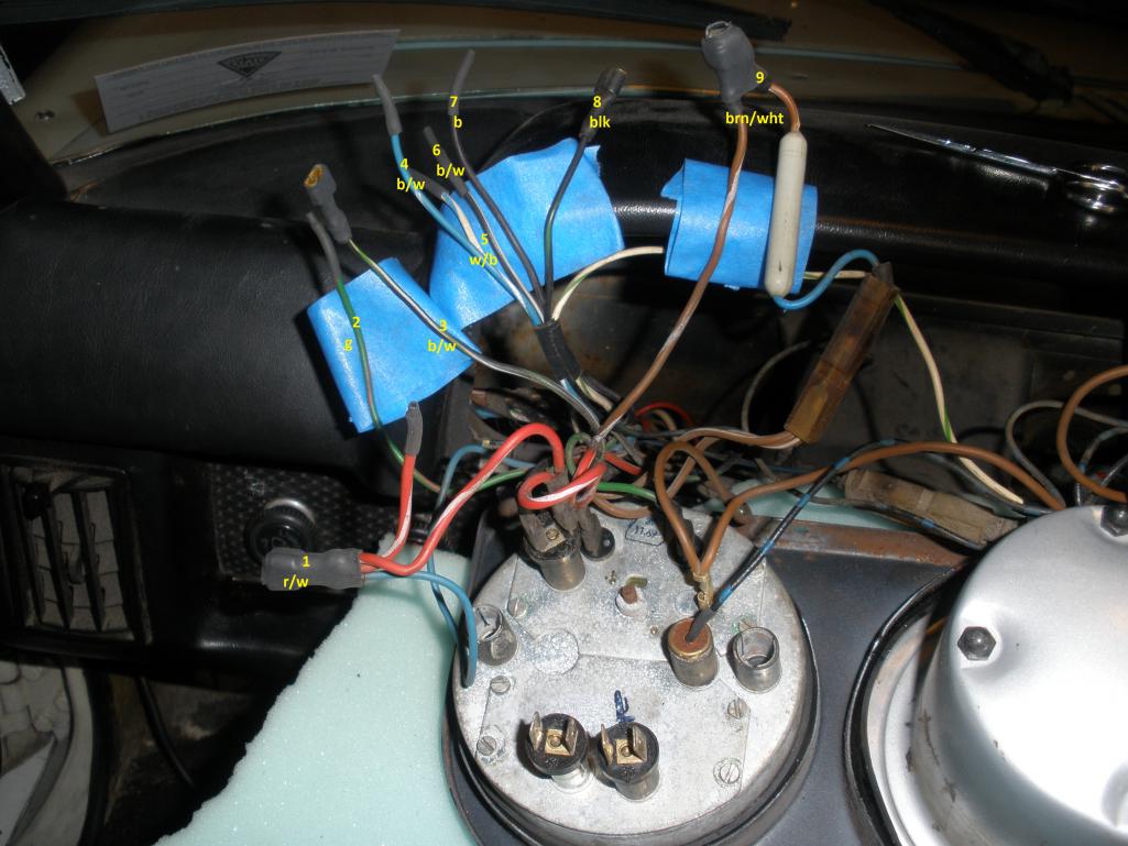 |
|
|
|
| HalfMoon |
Aug 29 2013, 01:16 PM
Post
#18
|
|
Senior Member Group: Members Posts: 828 Joined: 13-November 12 From: Shenandoah Junction, WV Member No.: 15,144 Region Association: MidAtlantic Region |
QUOTE(HalfMoon @ Aug 28 2013, 07:45 PM) Sigh. Well I goofed around with the pod wires some more today and we were right the wires 9, 10, 11 (from the previous photo's) were indeed illumination. So now I have a fuel gauge and the pods illuminated. Sadly I simply wasn't able to identify the turn signal wires (using a test light-I did find some that corresponded to the turn signal switch, but once tested, they would continue to flash on the dash even when off). I have at least achieved a working fuel gauge and pod illumination, so now I can drive it at night...if I'm brave. Most of the other things I didn't need nor would it be possible to connect them (e-brake for instance). The Gen, oil have dedicated gauges elsewhere and I know when my brights are on and when my brakes are having a pressure problem. Pity about the turn signals but the flasher makes a clicking noise when they're in use.... I've enclosed another picture of what is leftover that I have no idea about. Commentary welcome but please remember, this is a 1973 and is quite different than cars built after 1973. Anywho...thanks alot for all the imput but it's time to move on to some other pressing problems with this car. D Still quite baffled. I'd really like to identify what should be the illumination wires for the turn signal indicaters in the combo gauge. I thought I had it when I used a test light and operated the switch but when I placed the lever in the neutral position the flashers turned off but the indicater lights in the gauge kept flashing. I can't tell the color wires so they're numbered. Can anyone read the schematic (several post up) and tell me the number (very color blind) wires that "should" trigger the turn signal gauge lights? |
|
|
|
| bulitt |
Aug 29 2013, 02:47 PM
Post
#19
|
|
Achtzylinder Group: Members Posts: 4,188 Joined: 2-October 11 Member No.: 13,632 Region Association: South East States |
David- I crawled up on the lift to look at mine-
The turn signal bulbs each need a blue/white So hook up number 4 to one bulb and number 5 to the other bulb. Then each bulb needs either a black/white or black/green. So I'm guessing because they are taped together hook up the black/white - number 6 to the left indicator and the black/green - number 8 (yes it is black/green) to the right. Number three appears to be a black/white also? but outside the bunch taped together. Looks to me like you have a 1971 or 1972 fuel gauge? So looking at the 1973 schematic does you no good as the turn signal indicators in the 73 are in the tachometer. Is your speedo 120mph or 150? |
|
|
|
| HalfMoon |
Aug 29 2013, 03:47 PM
Post
#20
|
|
Senior Member Group: Members Posts: 828 Joined: 13-November 12 From: Shenandoah Junction, WV Member No.: 15,144 Region Association: MidAtlantic Region |
QUOTE(bulitt @ Aug 29 2013, 04:47 PM) David- I crawled up on the lift to look at mine- The turn signal bulbs each need a blue/white So hook up number 4 to one bulb and number 5 to the other bulb. Then each bulb needs either a black/white or black/green. So I'm guessing because they are taped together hook up the black/white - number 6 to the left indicator and the black/green - number 8 (yes it is black/green) to the right. Number three appears to be a black/white also? but outside the bunch taped together. Looks to me like you have a 1971 or 1972 fuel gauge? So looking at the 1973 schematic does you no good as the turn signal indicators in the 73 are in the tachometer. Is your speedo 120mph or 150? Thanks for that help, I'll try it a lil later on tonight. Big hopes! I do have the 1973 150 mph speedo (compared my back to the site you sent me), but I agree, the combo must be out of something earlier. Perhaps a PO thought to include turn signal indicators as they changed to an aftermarket tach to facilitate accuracy when converting to a v-8? Huge thank you for the insight and identification of those wires! |
|
|
|
|
1 User(s) are reading this topic (1 Guests and 0 Anonymous Users)
0 Members:

|
Lo-Fi Version | Time is now: 26th April 2024 - 11:56 AM |
Invision Power Board
v9.1.4 © 2024 IPS, Inc.