|
|
|
Porsche, and the Porsche crest are registered trademarks of Dr. Ing. h.c. F. Porsche AG.
This site is not affiliated with Porsche in any way. Its only purpose is to provide an online forum for car enthusiasts. All other trademarks are property of their respective owners. |
|
|


| 914forme |
 Sep 25 2013, 07:47 PM Sep 25 2013, 07:47 PM
Post
#41
|
|
Times a wastin', get wrenchin'!  Group: Members Posts: 3,899 Joined: 24-July 04 From: Dayton, Ohio Member No.: 2,388 Region Association: None |
Okay this is the car in all its glory ugly as heck, but hey its an auto-x car. (IMG:style_emoticons/default/new_shocked.gif) This one is from my first season of auto-x with this car.
 Heres what it looks like today. Made it even uglier (IMG:style_emoticons/default/barf.gif) 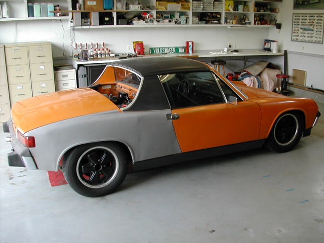 Here is the goal, I can sketch ideas, but I can not draw at the level of others on this forum. Thank you 914 Visulizer. and my black pen. Now if I could find a good front view. And the flares are not on the car since I'm not using GT Flares. 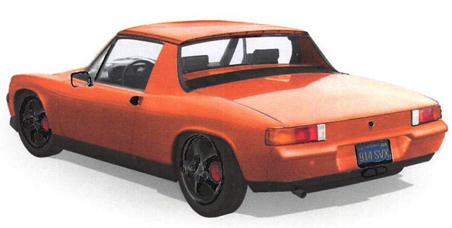 But you get the general idea. |
   |

 
|
Posts in this topic
914forme Signal Single Orange 74 EG33 Swap Sep 25 2013, 07:47 PM 914forme History:
After looking for 6 months I found this ... Sep 25 2013, 07:47 PM 914forme The Plan:
Make this thing like Steve Austin. The... Sep 25 2013, 07:48 PM turk22 I like the plan, the visualizer is nice, orange an... Sep 25 2013, 08:01 PM 914forme This weekend I pulled the torsion bar adjuster off... Sep 25 2013, 08:09 PM 914forme The rears fair much better. As I already did flar... Sep 25 2013, 08:21 PM kg6dxn You may want to get thinner front spacers to reduc... Sep 25 2013, 08:29 PM
914forme History:
After looking for 6 months I found this ... Sep 25 2013, 07:47 PM 914forme The Plan:
Make this thing like Steve Austin. The... Sep 25 2013, 07:48 PM turk22 I like the plan, the visualizer is nice, orange an... Sep 25 2013, 08:01 PM 914forme This weekend I pulled the torsion bar adjuster off... Sep 25 2013, 08:09 PM 914forme The rears fair much better. As I already did flar... Sep 25 2013, 08:21 PM kg6dxn You may want to get thinner front spacers to reduc... Sep 25 2013, 08:29 PM
 914forme
You may want to get thinner front spacers to redu... Sep 25 2013, 08:38 PM mepstein Its an H33 from a Subaru SVX, that I have just pic... Sep 25 2013, 08:42 PM ConeDodger You better have a whole bunch of power in that sco... Sep 26 2013, 01:42 PM Woody
You better have a whole bunch of power in that sc... Sep 26 2013, 02:23 PM 914forme I know y'alls hearts are in the right place, I... Sep 26 2013, 05:05 PM 914forme All the basic parts are in for the cable shifter. ... Sep 26 2013, 05:15 PM ConeDodger Not just the heavy... It's the diameter. If yo... Sep 26 2013, 05:32 PM 914forme
Not just the heavy... It's the diameter. If y... Sep 26 2013, 08:25 PM ConeDodger
Not just the heavy... It's the diameter. If ... Sep 26 2013, 08:47 PM 914forme And now for the rest of the good bits. The OBX ha... Sep 26 2013, 05:38 PM rick 918-S Can you re-drill the centerlines? I did that to a ... Sep 26 2013, 09:38 PM 914forme
Can you re-drill the centerlines? I did that to a... Sep 27 2013, 06:59 AM FourBlades Nice build! :smash:
Looking forward to see... Sep 27 2013, 07:53 AM 914forme Ha found wheel weights for 8.5"x15" Cent... Sep 27 2013, 10:33 AM 914forme Only got a work a little Saterday, and maybe an ho... Sep 29 2013, 08:22 PM 914forme Started working on the rotisserie. I should have ... Sep 29 2013, 08:33 PM 914forme Not much has happened over the last weekend. Life... Oct 8 2013, 10:40 AM Woody You'll have a hard time finding a tire to run ... Oct 8 2013, 12:24 PM 914forme
You'll have a hard time finding a tire to run... Oct 8 2013, 12:34 PM 914forme Okay things change in the world.
Centerline-ish w... Oct 31 2013, 03:21 PM 914forme Gathering the parts to do a 108mm rear CV swap int... Oct 31 2013, 03:36 PM 914forme My how time moves :blink:
Decided to get some p... Apr 23 2014, 06:59 AM Chris H. How did I miss this one? Did you get that donor c... Apr 23 2014, 09:36 AM 914forme
How did I miss this one? Did you get that donor ... Apr 23 2014, 11:09 AM Chris H. Wow. Yeah that would have been terrible. I'l... Apr 23 2014, 12:29 PM 914forme Yeah I saw the Super charger unit looked neat. Si... Apr 23 2014, 02:03 PM 914forme Okay well now lets continue down the long path of ... Apr 23 2014, 06:40 PM gryphon68
Still have a long way to go. Rinse and Repeat 40... Feb 16 2015, 10:30 AM 914forme
Still have a long way to go. Rinse and Repeat 4... Feb 17 2015, 11:07 AM 914forme And I started working on the rotisserie again.
Ma... Apr 23 2014, 06:57 PM 914forme Okay Post Lady brought me these today.
This is a ... Apr 23 2014, 07:16 PM Amenson Wow, of all of the great details in your build thr... Apr 24 2014, 10:59 AM 914forme
Wow, of all of the great details in your build th... Apr 24 2014, 05:54 PM Chris H. When you put a flat piece of glass on the 924 gaug... Apr 24 2014, 06:20 PM 914forme
When you put a flat piece of glass on the 924 gau... Apr 24 2014, 06:44 PM 914forme For todays update, I am tired of drilling holes fo... Apr 24 2014, 06:37 PM 914forme If I use this piece, I will need to redo the arche... Apr 24 2014, 06:50 PM Chris H. Hey that's cool Stephen....great idea. I... Apr 24 2014, 06:54 PM 914forme Yeah, now that the word is out Chris, you might wa... Apr 24 2014, 07:00 PM 914forme Rotisseri has been complete :welder:
I used a s... May 20 2014, 07:14 PM dan_the _body_guy
Rotisseri has been complete :welder:
I used a ... May 20 2014, 07:34 PM 914forme A lot has happened since I updated this thread. S... Feb 7 2015, 07:36 PM mgp4591 Oh yeah... :popcorn: Feb 8 2015, 07:05 AM 914forme I was told today I need to start posting more in m... Feb 12 2015, 05:08 PM altitude411 Just get new ones from 914rubber... http://shop.91... Feb 12 2015, 05:55 PM 914forme So this weekend I got busy on engine mount, and tr... Feb 17 2015, 11:23 AM 914forme Now making my first bad design I wanted to use so ... Feb 17 2015, 11:48 AM 914forme Yesterday I got a set of wheels I have been waitin... Feb 19 2015, 11:36 AM 914forme spent the day finishing stripping the car. Doors ... Feb 21 2015, 06:41 PM Chris H. Meant to post this...very pricey, but the Rocky Mo... Feb 21 2015, 07:29 PM 914forme Chris, Man them guys are expensive, and yes I have... Feb 22 2015, 07:20 PM mgp4591 Failed SD card is no excuse... still needs picture... Feb 22 2015, 10:57 PM Chris H. Yeah re: the RMW intake...the part I don't get... Feb 23 2015, 07:45 AM 914forme Bad SD Card reader / cable. :angry: I tossed some... Feb 23 2015, 07:57 AM 914forme Its been cold around here -15 the other day, and I... Feb 25 2015, 08:11 PM 914forme Old man winter did not keep me out of the shop yes... Mar 1 2015, 01:27 PM 914forme Works been hell this last week, so time for some 9... Mar 7 2015, 05:23 PM Dave_Darling I hope you marked the "rest" position of... Mar 7 2015, 07:42 PM 914forme
I hope you marked the "rest" position o... Mar 8 2015, 10:00 AM 914forme My wife had a 1990 Miata, I added a bunch of goodi... Jun 27 2015, 11:31 AM Amenson Stephen,
I was reading your post and all I could t... Jun 28 2015, 08:34 AM Chris H. Stephen...come back to the reservation...
DON... Jun 28 2015, 10:26 AM 914forme Scott, not to worry I talked with my wife this mor... Jun 28 2015, 05:40 PM Amenson
Scott, not to worry I talked with my wife this mo... Jun 28 2015, 07:04 PM 914forme :sawzall: :smash: :sawzall: The none fun stuff.... Jul 20 2015, 04:18 PM Amenson
:sawzall: :smash: :sawzall: The none fun stuff... Jul 21 2015, 08:43 AM 914forme Hmm, so I was reading the ForSale ad for the RS, s... Jul 28 2015, 05:42 PM 76-914 :poke: About time that you got busy again. :stir:... Jul 28 2015, 06:56 PM 914forme Not sure the guys name, I can't retrieve it cu... Jul 28 2015, 07:37 PM mepstein I thought craig at camp914 had done the RS tail li... Jul 28 2015, 08:31 PM 914forme Place called AR Concepts seems to have done them, ... Jul 29 2015, 05:41 PM 914forme Got the wrecked Miata out of the shop, hoping the ... Jul 31 2015, 06:18 PM 76-914 How close is your starter terminal to the chassis.... Jul 31 2015, 06:42 PM 914forme Yes thank you, I think I tested that, but maybe I ... Aug 1 2015, 04:35 AM 914forme First of Miata sold, one less temptress in my life... Aug 1 2015, 05:34 PM Andyrew
An now for an idea, well two really.
Pink id... Aug 2 2015, 11:13 PM 914forme Finished cutting and grinding all the engine shelf... Aug 2 2015, 05:50 PM Amenson With all that cleared out of the way there is plen... Aug 3 2015, 07:54 AM Chris H.
With all that cleared out of the way there is ple... Aug 12 2015, 09:29 PM jd74914
Speaking of turbo'd EG33's...anyone seen ... Aug 13 2015, 01:10 PM 914forme
[quote name='Chris H.' post='2222585' date='Aug 1... Aug 13 2015, 07:13 PM mgp4591
[quote name='Chris H.' post='2222585' date='Aug ... Aug 13 2015, 08:52 PM 914forme :agree:
I have my plans still trying to figure o... Aug 5 2015, 07:06 PM 914forme Weekend and back into the shop, long slow process ... Aug 10 2015, 06:28 AM 3d914
Templates are a good thing.
I will be doing so... Aug 15 2015, 10:49 AM mepstein Are you removing the engine bar motor mounts. Aug 10 2015, 06:57 AM 914forme Nope, using a Small Car Mount and an early -4 engi... Aug 10 2015, 07:15 AM mepstein I'll be pretty happy with the stock eg33 - hp.... Aug 13 2015, 08:59 PM mgp4591
I'll be pretty happy with the stock eg33 - hp... Aug 13 2015, 10:29 PM 914forme :agree:
Big injectors come fairly easy, I all re... Aug 14 2015, 03:14 AM Chris H. Wow Steve, I should just copy this last post of yo... Aug 15 2015, 08:37 AM 914forme Chris, not sure about the dual MAFs, unless you pu... Aug 15 2015, 03:12 PM 914forme Today's Progress:
Finished Hell Hole Template... Aug 15 2015, 07:22 PM
914forme
You may want to get thinner front spacers to redu... Sep 25 2013, 08:38 PM mepstein Its an H33 from a Subaru SVX, that I have just pic... Sep 25 2013, 08:42 PM ConeDodger You better have a whole bunch of power in that sco... Sep 26 2013, 01:42 PM Woody
You better have a whole bunch of power in that sc... Sep 26 2013, 02:23 PM 914forme I know y'alls hearts are in the right place, I... Sep 26 2013, 05:05 PM 914forme All the basic parts are in for the cable shifter. ... Sep 26 2013, 05:15 PM ConeDodger Not just the heavy... It's the diameter. If yo... Sep 26 2013, 05:32 PM 914forme
Not just the heavy... It's the diameter. If y... Sep 26 2013, 08:25 PM ConeDodger
Not just the heavy... It's the diameter. If ... Sep 26 2013, 08:47 PM 914forme And now for the rest of the good bits. The OBX ha... Sep 26 2013, 05:38 PM rick 918-S Can you re-drill the centerlines? I did that to a ... Sep 26 2013, 09:38 PM 914forme
Can you re-drill the centerlines? I did that to a... Sep 27 2013, 06:59 AM FourBlades Nice build! :smash:
Looking forward to see... Sep 27 2013, 07:53 AM 914forme Ha found wheel weights for 8.5"x15" Cent... Sep 27 2013, 10:33 AM 914forme Only got a work a little Saterday, and maybe an ho... Sep 29 2013, 08:22 PM 914forme Started working on the rotisserie. I should have ... Sep 29 2013, 08:33 PM 914forme Not much has happened over the last weekend. Life... Oct 8 2013, 10:40 AM Woody You'll have a hard time finding a tire to run ... Oct 8 2013, 12:24 PM 914forme
You'll have a hard time finding a tire to run... Oct 8 2013, 12:34 PM 914forme Okay things change in the world.
Centerline-ish w... Oct 31 2013, 03:21 PM 914forme Gathering the parts to do a 108mm rear CV swap int... Oct 31 2013, 03:36 PM 914forme My how time moves :blink:
Decided to get some p... Apr 23 2014, 06:59 AM Chris H. How did I miss this one? Did you get that donor c... Apr 23 2014, 09:36 AM 914forme
How did I miss this one? Did you get that donor ... Apr 23 2014, 11:09 AM Chris H. Wow. Yeah that would have been terrible. I'l... Apr 23 2014, 12:29 PM 914forme Yeah I saw the Super charger unit looked neat. Si... Apr 23 2014, 02:03 PM 914forme Okay well now lets continue down the long path of ... Apr 23 2014, 06:40 PM gryphon68
Still have a long way to go. Rinse and Repeat 40... Feb 16 2015, 10:30 AM 914forme
Still have a long way to go. Rinse and Repeat 4... Feb 17 2015, 11:07 AM 914forme And I started working on the rotisserie again.
Ma... Apr 23 2014, 06:57 PM 914forme Okay Post Lady brought me these today.
This is a ... Apr 23 2014, 07:16 PM Amenson Wow, of all of the great details in your build thr... Apr 24 2014, 10:59 AM 914forme
Wow, of all of the great details in your build th... Apr 24 2014, 05:54 PM Chris H. When you put a flat piece of glass on the 924 gaug... Apr 24 2014, 06:20 PM 914forme
When you put a flat piece of glass on the 924 gau... Apr 24 2014, 06:44 PM 914forme For todays update, I am tired of drilling holes fo... Apr 24 2014, 06:37 PM 914forme If I use this piece, I will need to redo the arche... Apr 24 2014, 06:50 PM Chris H. Hey that's cool Stephen....great idea. I... Apr 24 2014, 06:54 PM 914forme Yeah, now that the word is out Chris, you might wa... Apr 24 2014, 07:00 PM 914forme Rotisseri has been complete :welder:
I used a s... May 20 2014, 07:14 PM dan_the _body_guy
Rotisseri has been complete :welder:
I used a ... May 20 2014, 07:34 PM 914forme A lot has happened since I updated this thread. S... Feb 7 2015, 07:36 PM mgp4591 Oh yeah... :popcorn: Feb 8 2015, 07:05 AM 914forme I was told today I need to start posting more in m... Feb 12 2015, 05:08 PM altitude411 Just get new ones from 914rubber... http://shop.91... Feb 12 2015, 05:55 PM 914forme So this weekend I got busy on engine mount, and tr... Feb 17 2015, 11:23 AM 914forme Now making my first bad design I wanted to use so ... Feb 17 2015, 11:48 AM 914forme Yesterday I got a set of wheels I have been waitin... Feb 19 2015, 11:36 AM 914forme spent the day finishing stripping the car. Doors ... Feb 21 2015, 06:41 PM Chris H. Meant to post this...very pricey, but the Rocky Mo... Feb 21 2015, 07:29 PM 914forme Chris, Man them guys are expensive, and yes I have... Feb 22 2015, 07:20 PM mgp4591 Failed SD card is no excuse... still needs picture... Feb 22 2015, 10:57 PM Chris H. Yeah re: the RMW intake...the part I don't get... Feb 23 2015, 07:45 AM 914forme Bad SD Card reader / cable. :angry: I tossed some... Feb 23 2015, 07:57 AM 914forme Its been cold around here -15 the other day, and I... Feb 25 2015, 08:11 PM 914forme Old man winter did not keep me out of the shop yes... Mar 1 2015, 01:27 PM 914forme Works been hell this last week, so time for some 9... Mar 7 2015, 05:23 PM Dave_Darling I hope you marked the "rest" position of... Mar 7 2015, 07:42 PM 914forme
I hope you marked the "rest" position o... Mar 8 2015, 10:00 AM 914forme My wife had a 1990 Miata, I added a bunch of goodi... Jun 27 2015, 11:31 AM Amenson Stephen,
I was reading your post and all I could t... Jun 28 2015, 08:34 AM Chris H. Stephen...come back to the reservation...
DON... Jun 28 2015, 10:26 AM 914forme Scott, not to worry I talked with my wife this mor... Jun 28 2015, 05:40 PM Amenson
Scott, not to worry I talked with my wife this mo... Jun 28 2015, 07:04 PM 914forme :sawzall: :smash: :sawzall: The none fun stuff.... Jul 20 2015, 04:18 PM Amenson
:sawzall: :smash: :sawzall: The none fun stuff... Jul 21 2015, 08:43 AM 914forme Hmm, so I was reading the ForSale ad for the RS, s... Jul 28 2015, 05:42 PM 76-914 :poke: About time that you got busy again. :stir:... Jul 28 2015, 06:56 PM 914forme Not sure the guys name, I can't retrieve it cu... Jul 28 2015, 07:37 PM mepstein I thought craig at camp914 had done the RS tail li... Jul 28 2015, 08:31 PM 914forme Place called AR Concepts seems to have done them, ... Jul 29 2015, 05:41 PM 914forme Got the wrecked Miata out of the shop, hoping the ... Jul 31 2015, 06:18 PM 76-914 How close is your starter terminal to the chassis.... Jul 31 2015, 06:42 PM 914forme Yes thank you, I think I tested that, but maybe I ... Aug 1 2015, 04:35 AM 914forme First of Miata sold, one less temptress in my life... Aug 1 2015, 05:34 PM Andyrew
An now for an idea, well two really.
Pink id... Aug 2 2015, 11:13 PM 914forme Finished cutting and grinding all the engine shelf... Aug 2 2015, 05:50 PM Amenson With all that cleared out of the way there is plen... Aug 3 2015, 07:54 AM Chris H.
With all that cleared out of the way there is ple... Aug 12 2015, 09:29 PM jd74914
Speaking of turbo'd EG33's...anyone seen ... Aug 13 2015, 01:10 PM 914forme
[quote name='Chris H.' post='2222585' date='Aug 1... Aug 13 2015, 07:13 PM mgp4591
[quote name='Chris H.' post='2222585' date='Aug ... Aug 13 2015, 08:52 PM 914forme :agree:
I have my plans still trying to figure o... Aug 5 2015, 07:06 PM 914forme Weekend and back into the shop, long slow process ... Aug 10 2015, 06:28 AM 3d914
Templates are a good thing.
I will be doing so... Aug 15 2015, 10:49 AM mepstein Are you removing the engine bar motor mounts. Aug 10 2015, 06:57 AM 914forme Nope, using a Small Car Mount and an early -4 engi... Aug 10 2015, 07:15 AM mepstein I'll be pretty happy with the stock eg33 - hp.... Aug 13 2015, 08:59 PM mgp4591
I'll be pretty happy with the stock eg33 - hp... Aug 13 2015, 10:29 PM 914forme :agree:
Big injectors come fairly easy, I all re... Aug 14 2015, 03:14 AM Chris H. Wow Steve, I should just copy this last post of yo... Aug 15 2015, 08:37 AM 914forme Chris, not sure about the dual MAFs, unless you pu... Aug 15 2015, 03:12 PM 914forme Today's Progress:
Finished Hell Hole Template... Aug 15 2015, 07:22 PM  |
1 User(s) are reading this topic (1 Guests and 0 Anonymous Users)
0 Members:

|
Lo-Fi Version | Time is now: 26th May 2026 - 09:44 PM |
Invision Power Board
v9.1.4 © 2026 IPS, Inc.