|
|
|
Porsche, and the Porsche crest are registered trademarks of Dr. Ing. h.c. F. Porsche AG.
This site is not affiliated with Porsche in any way. Its only purpose is to provide an online forum for car enthusiasts. All other trademarks are property of their respective owners. |
|
|


| jd74914 |
 Dec 24 2013, 11:09 PM Dec 24 2013, 11:09 PM
Post
#61
|
|
Its alive  Group: Members Posts: 4,878 Joined: 16-February 04 From: CT Member No.: 1,659 Region Association: North East States |
Hello all.
I figured I’d throw up a progress thread for my car’s second rebuild. For those who don’t know me my name is James and I’ve been a 914 addict since age 13 (now 26) and used to hang around here a bunch more. It seems like a good start to this thread would be some background information. Its first build took place when I was in high school (age 13) and ended as a freshman in college. When I originally purchased the car it didn’t run and had some pretty serious external rust problems. I rebuilt the motor, fixed tons of electrical issues, replaced all of the rotten metal with new (all hand-formed since I didn’t have the money to pay for reproduction pieces), and repainted. Everything was done in my garage with the exception of turning/balancing the flywheel and I learned how to MIG weld and paint from my dad, some books, and through a lot of practice. After reassembly, it was my daily driver for 3.5 years during my undergrad degree. I pretty much drove it hard and put it away wet for the entirety of these years and it never saw a garage. Something about getting a mechanical engineering degree, dating a few girls, working throughout the year as a design engineering intern, and finding FSAE cars really limited the amount of time I spend on my own car. By the end of my undergrad degree there were some pretty rough spots, mostly in terms of the suspension/brakes and a pesky ignition switch (replaced 3 or 4 times and it kept failing), which pushed me to taking it off the road and fixing everything correctly. I thought it might take about a year-that was 3.5 years ago! (IMG:style_emoticons/default/wacko.gif) Just like after the first rebuild, life got in the way and the car sat as I went through a master’s degree, worked full time, continued to play with FSAE cars, and starting working on friend’s real racecars. Now I’ve finally finished my MS (and know way too much about fluid dynamics and heat transfer (IMG:style_emoticons/default/laugh.gif) ), am applying to schools for a Ph.D., still haven’t stopped [advising] FSAE design, and really want to drive her! The play was to start and finish rebuilding the suspension last summer (I saw Chris Foley-Racer Chris in the grocery store one day and told him this), but I got carried away and a bit behind. This thread is to chronicle the build back to the road. We’ll start with a few pictures from when it was originally completed in 2006/7 (well, it's missing the plates and still has the original windshield but...). 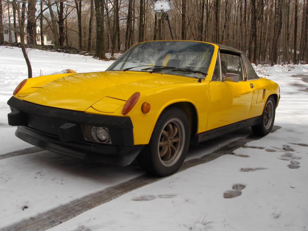 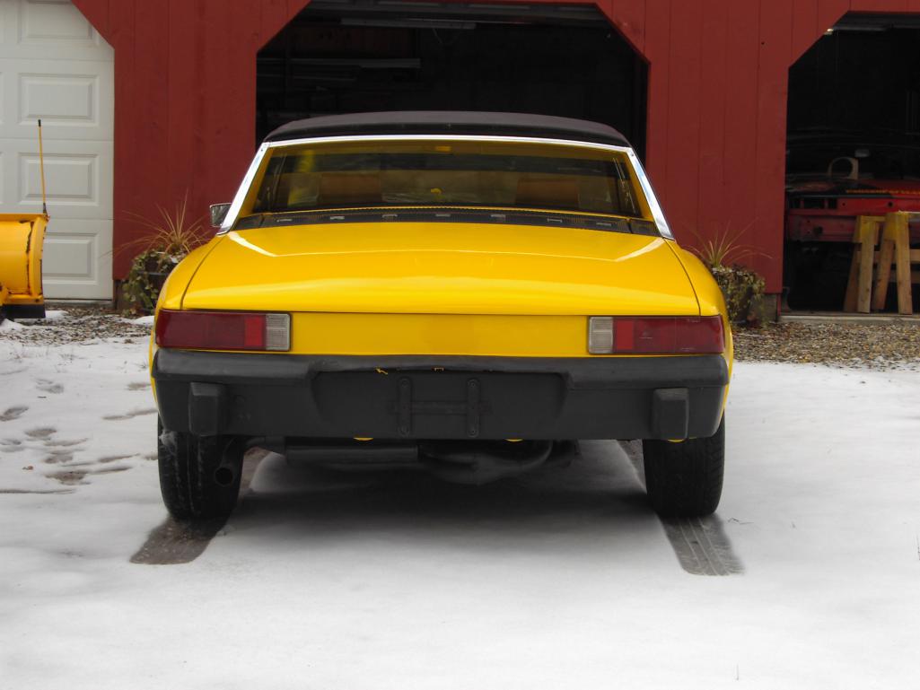 |
   |

 
|
Posts in this topic
 jd74914 Build #2 Dec 24 2013, 11:09 PM
 jd74914 ***** Hijack Start *****
Since it’s been my main... Dec 24 2013, 11:41 PM jd74914 And a few shop pics just because...There is a nice... Dec 24 2013, 11:46 PM RobW Good luck with your build(s).... Dec 25 2013, 07:31 AM r_towle Good to see you back at it again, now stop getting... Dec 25 2013, 10:40 PM jd74914 Thanks Rich and Rob...I'm definitely trying to... Dec 25 2013, 11:55 PM jd74914 Off came the fender for easy cutting into the long... Dec 26 2013, 12:04 AM jd74914 Once the cutting started, I had a really hard time... Dec 26 2013, 12:15 AM jd74914 A few more pictures of the suspension console and ... Dec 26 2013, 12:38 AM Cairo94507 Terrific story and glad to see you are working tow... Dec 26 2013, 09:17 AM
jd74914 ***** Hijack Start *****
Since it’s been my main... Dec 24 2013, 11:41 PM jd74914 And a few shop pics just because...There is a nice... Dec 24 2013, 11:46 PM RobW Good luck with your build(s).... Dec 25 2013, 07:31 AM r_towle Good to see you back at it again, now stop getting... Dec 25 2013, 10:40 PM jd74914 Thanks Rich and Rob...I'm definitely trying to... Dec 25 2013, 11:55 PM jd74914 Off came the fender for easy cutting into the long... Dec 26 2013, 12:04 AM jd74914 Once the cutting started, I had a really hard time... Dec 26 2013, 12:15 AM jd74914 A few more pictures of the suspension console and ... Dec 26 2013, 12:38 AM Cairo94507 Terrific story and glad to see you are working tow... Dec 26 2013, 09:17 AM
 jd74914
Terrific story and glad to see you are working to... Dec 27 2013, 01:59 AM Racer Chris Wow, a little bit of project creep there. Better n... Dec 27 2013, 07:59 AM r_towle When the heck did you do that? Last week?
And Chr... Dec 27 2013, 06:38 PM jd74914
Wow, a little bit of project creep there. Better ... Dec 27 2013, 11:52 PM saigon71 Looking good...especially the jig to insure the su... Dec 28 2013, 08:45 AM jd74914 A late thanks Bob! :)
I was going through my ... Dec 29 2014, 03:09 PM Racer Chris
...
, lost my job due to company bankruptcy,
...... Dec 29 2014, 03:15 PM jd74914
[quote name='jd74914' post='2127655' date='Dec 29... Dec 29 2014, 03:46 PM jd74914 RE: Build #2 Dec 29 2014, 03:10 PM r_towle is the car originally green, orange, or yellow? Dec 29 2014, 03:23 PM jd74914 Over the course of last winter, I couldn't sto... Dec 29 2014, 03:43 PM jd74914 The trailing arm mounts were moved up by about 1.8... Dec 29 2014, 03:59 PM jd74914 And just for fun some new stuff...
The trigger wh... Dec 29 2014, 04:08 PM jd74914 Then chuckc here had a great deal on some phonedia... Dec 29 2014, 04:14 PM Phoenix914
That's all I've got! Hopefully the n... Dec 29 2014, 04:36 PM jd74914
I certainly hope so. This is just getting good... Dec 30 2014, 02:53 PM Chris Pincetich Curious about that trailing arm inner and your str... Dec 30 2014, 03:35 PM jd74914
Curious about that trailing arm inner and your st... Dec 31 2014, 11:36 AM FourBlades Awesome job rebuilding the long! :first:
Le... Dec 31 2014, 11:45 AM Mueller Great progress.....
Have you considered using mis... Dec 31 2014, 01:39 PM yeahmag Andy and I talked about this a bit. The problem is... Dec 31 2014, 03:25 PM Jeff Hail The inner ear will bend/deflect a little bit when ... Dec 31 2014, 06:58 PM jeff This setup should eliminate the bind when adjustin... Dec 31 2014, 10:52 PM jd74914
Awesome job rebuilding the long!
Thanks... Jan 1 2015, 01:09 PM jd74914 A few more pieces. I seam welded the trailing arm ... Jan 9 2015, 07:05 PM jd74914 Forgot to add this in the last post...
Those trai... Jan 9 2015, 08:17 PM veekry9 I missed this thread last year as I was off on oth... Jan 9 2015, 08:46 PM jd74914 Finally did a little more work this weekend after ... Sep 14 2015, 07:46 AM jd74914 October 2016 Update:
Not much got done this month... Oct 31 2016, 06:37 PM 914forme
Additionally, I started designing the mounts and ... Nov 13 2016, 06:21 PM jd74914
really love what your doing but over complicating... Dec 29 2016, 11:53 AM jd74914 I picked up a gearbox off Craigslist this week. It... Nov 12 2016, 05:18 PM jd74914 Ok, I guess the spreadsheet add doesn't work f... Nov 12 2016, 05:22 PM jd74914 I got a sweet set of single adjustable JRZ shocks ... Dec 20 2016, 10:46 AM 914forme
I got a sweet set of single adjustable JRZ shocks... Dec 20 2016, 12:24 PM jd74914
Nice job on the spacers.
Thanks! Spending l... Dec 22 2016, 04:59 PM jd74914 Also pulled the intake wiring harness off. With al... Dec 20 2016, 11:10 AM jd74914 Next up are some TGV deletes. I really just starte... Dec 22 2016, 05:22 PM jd74914 Another view of the material taken out with slight... Dec 22 2016, 05:26 PM 914forme Nice design Dec 29 2016, 12:32 PM jd74914
Nice design
Thanks! Hopefully it works ok..... Dec 29 2016, 04:18 PM 914_teener Interesting...gosh I wish I had the toys and tools... Dec 29 2016, 04:34 PM jd74914
Interesting...gosh I wish I had the toys and tool... Dec 29 2016, 05:44 PM 914forme Collar on the outside it is a functional piece not... Dec 29 2016, 06:33 PM jd74914
BTW, Mine using a standard spherical bearing and ... Dec 29 2016, 07:19 PM 914forme Jim
3/8" due to me having a huge number of 3... Dec 30 2016, 07:44 AM jd74914
3/8" due to me having a huge number of 3/8... Jan 4 2017, 04:38 PM jd74914 Finished the TGV removal finally! One more par... Jan 4 2017, 04:54 PM jd74914 The final product after hitting it with a 60-grit ... Jan 4 2017, 04:56 PM jd74914 Also unpacked the left rear inner fender wheel Chr... Jan 4 2017, 04:58 PM tygaboy
Also unpacked the left rear inner fender wheel Ch... Jan 9 2017, 06:22 PM jd74914
It's true, I really do rule...
:lol4:
Re... Jan 9 2017, 06:31 PM jd74914 Changing the sway bar mounts slightly to accommoda... Jan 9 2017, 04:30 PM jd74914 Finished up the sway bar bearing mounts over lunch... Jan 11 2017, 03:01 PM tygaboy LOVE those sway bar bearing mounts! Just beaut... Jan 11 2017, 03:31 PM jd74914
LOVE those sway bar bearing mounts! Just beau... Jan 11 2017, 05:09 PM Curbandgutter Jim, your tractive force spreadsheet proves that i... Jan 17 2017, 11:00 PM jd74914 Haven't gotten too much done in the last few w... Jan 30 2017, 05:20 PM jd74914 Framed out the necessary larger holes in the sway ... Jan 31 2017, 05:25 PM jd74914 Threw together the first iteration of the front sw... Jan 31 2017, 06:44 PM Racer Chris
Anyone have any thoughts?
I think I like your ... Feb 1 2017, 04:10 PM Andyrew Very cool design on the sway bar arms.
Let me kn... Feb 1 2017, 01:19 AM jd74914
Very cool design on the sway bar arms.
Let me k... Feb 1 2017, 03:55 PM Curbandgutter Wow we have talent on this forum yalll!! Feb 1 2017, 08:42 AM jd74914 Working really slowly this month...too much other ... Mar 1 2017, 12:54 PM jd74914 Pulled apart bad center diff ready for cutting.
Mar 1 2017, 12:54 PM jd74914 Cut up the differential last night and test fit in... Mar 10 2017, 09:53 AM jd74914 Crudely filed housing splines. You can see where i... Mar 10 2017, 09:57 AM jd74914 Of course it wouldn't slide out of the differe... Mar 10 2017, 10:04 AM jd74914 No real car progress to report. My crazy school sc... Nov 11 2017, 02:45 PM Racer Chris Jim, I have a really big rotary phase converter at... Nov 12 2017, 06:41 AM 914forme Updates? :poke: :confused: Sep 14 2018, 05:32 PM
jd74914
Terrific story and glad to see you are working to... Dec 27 2013, 01:59 AM Racer Chris Wow, a little bit of project creep there. Better n... Dec 27 2013, 07:59 AM r_towle When the heck did you do that? Last week?
And Chr... Dec 27 2013, 06:38 PM jd74914
Wow, a little bit of project creep there. Better ... Dec 27 2013, 11:52 PM saigon71 Looking good...especially the jig to insure the su... Dec 28 2013, 08:45 AM jd74914 A late thanks Bob! :)
I was going through my ... Dec 29 2014, 03:09 PM Racer Chris
...
, lost my job due to company bankruptcy,
...... Dec 29 2014, 03:15 PM jd74914
[quote name='jd74914' post='2127655' date='Dec 29... Dec 29 2014, 03:46 PM jd74914 RE: Build #2 Dec 29 2014, 03:10 PM r_towle is the car originally green, orange, or yellow? Dec 29 2014, 03:23 PM jd74914 Over the course of last winter, I couldn't sto... Dec 29 2014, 03:43 PM jd74914 The trailing arm mounts were moved up by about 1.8... Dec 29 2014, 03:59 PM jd74914 And just for fun some new stuff...
The trigger wh... Dec 29 2014, 04:08 PM jd74914 Then chuckc here had a great deal on some phonedia... Dec 29 2014, 04:14 PM Phoenix914
That's all I've got! Hopefully the n... Dec 29 2014, 04:36 PM jd74914
I certainly hope so. This is just getting good... Dec 30 2014, 02:53 PM Chris Pincetich Curious about that trailing arm inner and your str... Dec 30 2014, 03:35 PM jd74914
Curious about that trailing arm inner and your st... Dec 31 2014, 11:36 AM FourBlades Awesome job rebuilding the long! :first:
Le... Dec 31 2014, 11:45 AM Mueller Great progress.....
Have you considered using mis... Dec 31 2014, 01:39 PM yeahmag Andy and I talked about this a bit. The problem is... Dec 31 2014, 03:25 PM Jeff Hail The inner ear will bend/deflect a little bit when ... Dec 31 2014, 06:58 PM jeff This setup should eliminate the bind when adjustin... Dec 31 2014, 10:52 PM jd74914
Awesome job rebuilding the long!
Thanks... Jan 1 2015, 01:09 PM jd74914 A few more pieces. I seam welded the trailing arm ... Jan 9 2015, 07:05 PM jd74914 Forgot to add this in the last post...
Those trai... Jan 9 2015, 08:17 PM veekry9 I missed this thread last year as I was off on oth... Jan 9 2015, 08:46 PM jd74914 Finally did a little more work this weekend after ... Sep 14 2015, 07:46 AM jd74914 October 2016 Update:
Not much got done this month... Oct 31 2016, 06:37 PM 914forme
Additionally, I started designing the mounts and ... Nov 13 2016, 06:21 PM jd74914
really love what your doing but over complicating... Dec 29 2016, 11:53 AM jd74914 I picked up a gearbox off Craigslist this week. It... Nov 12 2016, 05:18 PM jd74914 Ok, I guess the spreadsheet add doesn't work f... Nov 12 2016, 05:22 PM jd74914 I got a sweet set of single adjustable JRZ shocks ... Dec 20 2016, 10:46 AM 914forme
I got a sweet set of single adjustable JRZ shocks... Dec 20 2016, 12:24 PM jd74914
Nice job on the spacers.
Thanks! Spending l... Dec 22 2016, 04:59 PM jd74914 Also pulled the intake wiring harness off. With al... Dec 20 2016, 11:10 AM jd74914 Next up are some TGV deletes. I really just starte... Dec 22 2016, 05:22 PM jd74914 Another view of the material taken out with slight... Dec 22 2016, 05:26 PM 914forme Nice design Dec 29 2016, 12:32 PM jd74914
Nice design
Thanks! Hopefully it works ok..... Dec 29 2016, 04:18 PM 914_teener Interesting...gosh I wish I had the toys and tools... Dec 29 2016, 04:34 PM jd74914
Interesting...gosh I wish I had the toys and tool... Dec 29 2016, 05:44 PM 914forme Collar on the outside it is a functional piece not... Dec 29 2016, 06:33 PM jd74914
BTW, Mine using a standard spherical bearing and ... Dec 29 2016, 07:19 PM 914forme Jim
3/8" due to me having a huge number of 3... Dec 30 2016, 07:44 AM jd74914
3/8" due to me having a huge number of 3/8... Jan 4 2017, 04:38 PM jd74914 Finished the TGV removal finally! One more par... Jan 4 2017, 04:54 PM jd74914 The final product after hitting it with a 60-grit ... Jan 4 2017, 04:56 PM jd74914 Also unpacked the left rear inner fender wheel Chr... Jan 4 2017, 04:58 PM tygaboy
Also unpacked the left rear inner fender wheel Ch... Jan 9 2017, 06:22 PM jd74914
It's true, I really do rule...
:lol4:
Re... Jan 9 2017, 06:31 PM jd74914 Changing the sway bar mounts slightly to accommoda... Jan 9 2017, 04:30 PM jd74914 Finished up the sway bar bearing mounts over lunch... Jan 11 2017, 03:01 PM tygaboy LOVE those sway bar bearing mounts! Just beaut... Jan 11 2017, 03:31 PM jd74914
LOVE those sway bar bearing mounts! Just beau... Jan 11 2017, 05:09 PM Curbandgutter Jim, your tractive force spreadsheet proves that i... Jan 17 2017, 11:00 PM jd74914 Haven't gotten too much done in the last few w... Jan 30 2017, 05:20 PM jd74914 Framed out the necessary larger holes in the sway ... Jan 31 2017, 05:25 PM jd74914 Threw together the first iteration of the front sw... Jan 31 2017, 06:44 PM Racer Chris
Anyone have any thoughts?
I think I like your ... Feb 1 2017, 04:10 PM Andyrew Very cool design on the sway bar arms.
Let me kn... Feb 1 2017, 01:19 AM jd74914
Very cool design on the sway bar arms.
Let me k... Feb 1 2017, 03:55 PM Curbandgutter Wow we have talent on this forum yalll!! Feb 1 2017, 08:42 AM jd74914 Working really slowly this month...too much other ... Mar 1 2017, 12:54 PM jd74914 Pulled apart bad center diff ready for cutting.
Mar 1 2017, 12:54 PM jd74914 Cut up the differential last night and test fit in... Mar 10 2017, 09:53 AM jd74914 Crudely filed housing splines. You can see where i... Mar 10 2017, 09:57 AM jd74914 Of course it wouldn't slide out of the differe... Mar 10 2017, 10:04 AM jd74914 No real car progress to report. My crazy school sc... Nov 11 2017, 02:45 PM Racer Chris Jim, I have a really big rotary phase converter at... Nov 12 2017, 06:41 AM 914forme Updates? :poke: :confused: Sep 14 2018, 05:32 PM  |
1 User(s) are reading this topic (1 Guests and 0 Anonymous Users)
0 Members:

|
Lo-Fi Version | Time is now: 26th May 2026 - 10:39 PM |
Invision Power Board
v9.1.4 © 2026 IPS, Inc.