|
|
|
Porsche, and the Porsche crest are registered trademarks of Dr. Ing. h.c. F. Porsche AG.
This site is not affiliated with Porsche in any way. Its only purpose is to provide an online forum for car enthusiasts. All other trademarks are property of their respective owners. |
|
|

  |

| stephestrad |
 Jan 2 2014, 03:13 PM Jan 2 2014, 03:13 PM
Post
#1
|
|
Newbie  Group: Members Posts: 18 Joined: 28-February 13 From: Berkeley, CA Member No.: 15,596 Region Association: Northern California |
Yesterday, I started installing new targa-to-window weatherstripping -- the pieces that run along each side of the roof and seal against the top of the windows. I noticed that the curvature of the restraining pieces, the parts into which the weatherstripping slide, do not follow the curve of the roof but instead, bow inward.
Is this normal? Should the curve of the weatherstripping match that of roof? Is there any chance these have been installed backwards and the curve should follow the roof? I'm guessing it's correct as-is, but I was hoping for some confirmation. 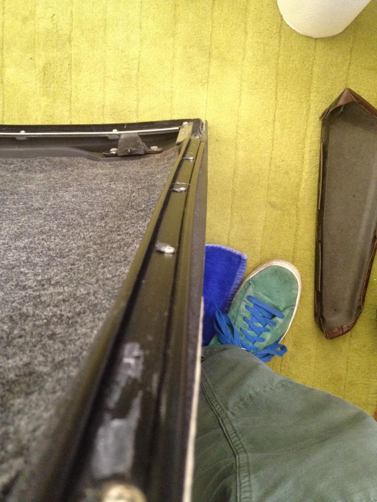 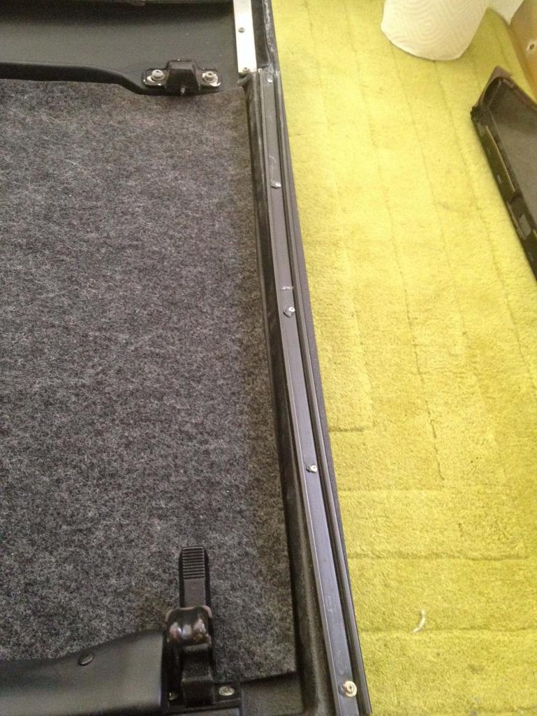 |
   |

 
|
| cal914 |
Jan 2 2014, 03:48 PM
Post
#2
|
|
Member Group: Members Posts: 319 Joined: 12-April 12 From: United Kingdom Member No.: 14,366 Region Association: None |
I did the same thing today and when i saw the curve i thought it must have been wrong ,but seeing your post make's me think it's correct
Brian |
|
|
|
| stephestrad |
Jan 2 2014, 04:20 PM
Post
#3
|
|
Newbie Group: Members Posts: 18 Joined: 28-February 13 From: Berkeley, CA Member No.: 15,596 Region Association: Northern California |
That's comforting. Yeah, the odds of them both being wrong seem slim.
Thanks! Stephen |
|
|
|
| Mikey914 |
Jan 2 2014, 04:24 PM
Post
#4
|
|
The rubber man Group: Members Posts: 12,669 Joined: 27-December 04 From: Hillsboro, OR Member No.: 3,348 Region Association: None |
You will notice the holes are slotted, so there is some adjustment, the metal is soft and is easily deformed, so you can "adjust" as necessary.
|
|
|
|
| ned911 |
Jan 24 2014, 04:11 PM
Post
#5
|
|
Member Group: Members Posts: 54 Joined: 11-September 12 From: Austin, TX Member No.: 14,912 Region Association: Southwest Region |
Any tips on the best way to remove the old strip and install the new ones?
|
|
|
|
| nihil44 |
Jan 24 2014, 07:59 PM
Post
#6
|
|
Member Group: Members Posts: 157 Joined: 28-January 12 From: Brisbane, Australia Member No.: 14,058 Region Association: None |
Yep. Just done mine and had to use immense patience.
The aluminium (that's the way we spell it downunder) strip originally was sealed with that sticky awful butyl rubber stuff to stop water entry under the metal strip. I was thinking of using silicone but used a strip of closed cell foam (plastic or rubber like the material Mark 914 rubber uses) to effect the seal. I would say be careful placing the mitred end (the rear end) as it needs to meet the vertical targa seal to make a water tight seal but also needs not to be positioned too far back that it doesn't allow the targa to pull down. I will see if I can add a little later,. Just heading out. David Brisbane, Australia |
|
|
|
| nihil44 |
Jan 25 2014, 01:18 AM
Post
#7
|
|
Member Group: Members Posts: 157 Joined: 28-January 12 From: Brisbane, Australia Member No.: 14,058 Region Association: None |
if you find that the glass isn't touching the rubber and therefore not making a seal, you can adjust the inward tilt of the top of the window by adjusting the slotted screw at the bottom of the door.
I will try to add some photos to illustrate. This may have been documented before I discovered these things by the painful method of trial and error. David Attached thumbnail(s) 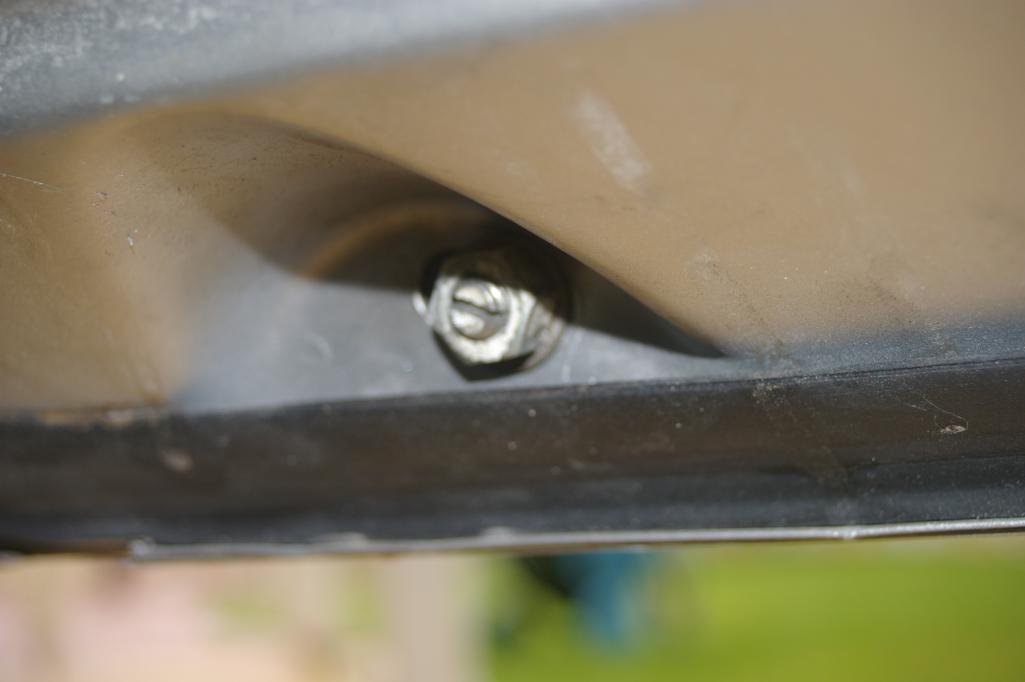 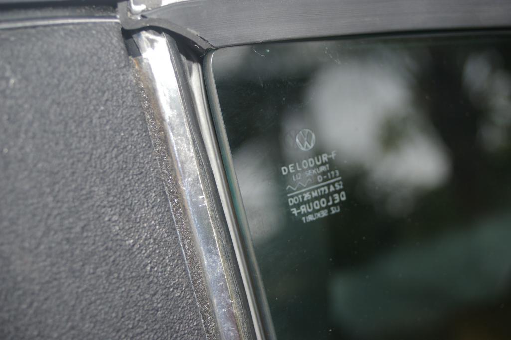
|
|
|
|
| nihil44 |
Jan 25 2014, 01:20 AM
Post
#8
|
|
Member Group: Members Posts: 157 Joined: 28-January 12 From: Brisbane, Australia Member No.: 14,058 Region Association: None |
Internal view of adjustment screw
Attached thumbnail(s) 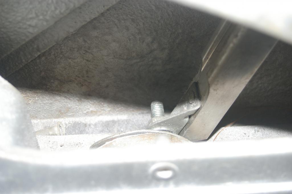
|
|
|
|
|
1 User(s) are reading this topic (1 Guests and 0 Anonymous Users)
0 Members:

|
Lo-Fi Version | Time is now: 17th May 2024 - 08:44 PM |
Invision Power Board
v9.1.4 © 2024 IPS, Inc.