|
|
|
Porsche, and the Porsche crest are registered trademarks of Dr. Ing. h.c. F. Porsche AG.
This site is not affiliated with Porsche in any way. Its only purpose is to provide an online forum for car enthusiasts. All other trademarks are property of their respective owners. |
|
|

  |

| scruz914 |
 Jan 28 2005, 07:09 PM Jan 28 2005, 07:09 PM
Post
#1
|
|
Senior Member  Group: Members Posts: 815 Joined: 26-February 04 From: Santa Cruz, CA Member No.: 1,724 |
I am pretty sure this will look huge so don't get on my case. I wanted to post it to see if someone can proof it. I don't have a place to put it for a link so if an admin wants to help I would appreciate it. The original is in Visio and I would like to layer it into the different circuts. Feedback and proof reading is appreciated.
-Jeff Attached thumbnail(s) 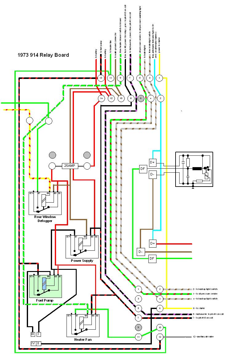
|
   |

 
|
| Dr Evil |
Jan 28 2005, 07:20 PM
Post
#2
|
|
Send me your transmission! Group: Members Posts: 22,995 Joined: 21-November 03 From: Loveland, OH 45140 Member No.: 1,372 Region Association: MidAtlantic Region |
Thats the version of Visio that I need to get. I don't have the electrical part. If you look in the resources section under "free electrical resource", I am doing every circuit in the car in the simplest way. I like what you have done. Would you like to post this to my resource thread? It would help.
|
|
|
|
| scruz914 |
Jan 28 2005, 07:30 PM
Post
#3
|
|
Senior Member Group: Members Posts: 815 Joined: 26-February 04 From: Santa Cruz, CA Member No.: 1,724 |
Mike,
I have seen your resource thread. It was sort of the tirgger that got me going on this. That plus I am thinking about how to redesign the relay board to use a standard regulator, soft shell connectors, and maybe solid state relays (if they can be done efficiently). Sure I will post the diagram on your resource thread but I want to have someone proof read it first. I would also like to clean it up some more so it converts to a bitmap a little better. Regarding Visio. I am using the plain old standard version and templates. I created the wire colors as patterns so any line can be drawn in the real colors. I also drew the relay and regulator and grouped the objects into a single image for copying and sizing. I would be happy to share. -Jeff |
|
|
|
| skline |
Jan 28 2005, 07:32 PM
Post
#4
|
|
Born to Drive Group: Members Posts: 7,910 Joined: 26-December 02 From: Costa Mesa, CA Member No.: 17 Region Association: Southern California |
Hey Mike, I told you I got what you need. We just never got the chance to get it to you. When you coming up this way again?
|
|
|
|
| DNHunt |
Jan 28 2005, 07:49 PM
Post
#5
|
|
914 Wizard? No way. I got too much to learn. Group: Members Posts: 4,099 Joined: 21-April 03 From: Gig Harbor, WA Member No.: 598 |
That is really cool. I'm sure I'll be looking at it a bunch
Dave |
|
|
|
| Howard |
Jan 28 2005, 07:52 PM
Post
#6
|
|
Incontin(g)ent Member Group: Benefactors Posts: 5,785 Joined: 24-July 03 From: Westlake Village, CA Member No.: 943 Region Association: None |
Jeff, thanks. One my tired old eyes can actually read. This should be saved in the FTP section.
|
|
|
|
| Dr Evil |
Jan 28 2005, 07:58 PM
Post
#7
|
|
Send me your transmission! Group: Members Posts: 22,995 Joined: 21-November 03 From: Loveland, OH 45140 Member No.: 1,372 Region Association: MidAtlantic Region |
Scott,
if you can get it to Aaron, he is coming down tomarrow. I will likely need to come up there anyway to have you resolve my issues with the Mega Jolt software (yo no hablo). |
|
|
|
| jd74914 |
Jan 28 2005, 09:01 PM
Post
#8
|
|
Its alive Group: Members Posts: 4,780 Joined: 16-February 04 From: CT Member No.: 1,659 Region Association: North East States |
the diagram is much better in color than black and right (IMG:http://www.914world.com/bbs2/html/emoticons/biggrin.gif)
congrats, its really nice (IMG:http://www.914world.com/bbs2/html/emoticons/smilie_pokal.gif) (IMG:http://www.914world.com/bbs2/html/emoticons/smilie_pokal.gif) |
|
|
|
| bperry |
Jan 29 2005, 01:58 AM
Post
#9
|
|
Lurker Group: Members Posts: 477 Joined: 16-February 04 From: Dallas, Tx Member No.: 1,661 |
Really nice! The problem with the factory wiring diagram picture is
that they didn't label where the colored wires went and its a real pain to track them down. A few things you may want to look at. Perhaps label the connectors? T4, T12, T14 Label the Fuse? S13 Add "to Alternator" on the 3 wires (red, brown, green) below the regulator Did notice what looks like typos: T14-3 should be backup light switch not brake light switch T14-4 should be backup lights not brake liights. T12-4 should be backup lights not backup light switch Perhaps grey out T12-3 if it really is a no connect. The only thing I miss in this drawing is the actual orientation of the pins on the relays & sockets, but its not too hard to figure out by looking at the bottom of the relay. Overall, it's definitely an improvement. --- What's funny is I've always had both fuses in my relay board. The front fuse (the one not shown in your picture) powers T12-9 but I can't find where T12-9 goes. Tomorrow I'll have to crack open the connector in my car and see if it really is a no connect. I going to do the same for T16-6 and T12-3 Looks really nice! (IMG:http://www.914world.com/bbs2/html/emoticons/aktion035.gif) --- Bill |
|
|
|
| SirAndy |
Jan 29 2005, 03:33 AM
Post
#10
|
|
Resident German Group: Admin Posts: 41,634 Joined: 21-January 03 From: Oakland, Kalifornia Member No.: 179 Region Association: Northern California |
so, what's wrong with the factory color diagrams ???? (IMG:http://www.914world.com/bbs2/html/emoticons/confused24.gif)
nice work, but ........ why? (IMG:http://www.914world.com/bbs2/html/emoticons/idea.gif) Andy |
|
|
|
| SpecialK |
Jan 29 2005, 05:04 AM
Post
#11
|
|
aircraft surgeon Group: Benefactors Posts: 3,211 Joined: 15-March 04 From: Pacific, MO Member No.: 1,797 |
I'd like to know which version of Visio you used also. I tried to make my "custom homebuilt" wiring diagrams on MultiSimm (too "electronics") and MS Paint (too....well, MS Paint), because my color codes won't be exactly to spec when it's done. It won't be such a problem for me since I'm making the wire harness.........more for the poor bastard that inherits the '73 after it puts me in the ground.
|
|
|
|
| gregrobbins |
Jan 29 2005, 01:42 PM
Post
#12
|
|
Member: Team NARP Group: Members Posts: 1,515 Joined: 23-March 04 From: Arizona Member No.: 1,844 Region Association: Southwest Region |
Nice job, thanks for posting.
|
|
|
|
| BigD9146gt |
Jan 29 2005, 02:32 PM
Post
#13
|
|
OCD member Group: Members Posts: 376 Joined: 24-January 05 From: Sydney, Australia Member No.: 3,502 Region Association: Australia and New Zealand |
Nice drawing! (IMG:http://www.914world.com/bbs2/html/emoticons/beerchug.gif)
Even thought the stock drawings will suffice, its always nice to have a complete printout with all the labels right on the wires and relays... makes for a faster search. Heres a wiring diagram i made (i don't think this is the completed version though), of a wiring diagram i made for my 73 914... inwhich i installed a complete dash, gauges, steering column and switches, front wiring harness, and fuse panel all from a 70 911. I first did it all out on paper, then moved it over to Microsoft Paint... It took along time, but it does the job. You can never have enough wiring diagrams! (IMG:http://forums.pelicanparts.com/uploads4/9146GT%20WIRING10939055911107030346.jpg) t. |
|
|
|
| SpecialK |
Jan 29 2005, 04:10 PM
Post
#14
|
|
aircraft surgeon Group: Benefactors Posts: 3,211 Joined: 15-March 04 From: Pacific, MO Member No.: 1,797 |
You did that with MS Paint? Very nice!! (IMG:http://www.914world.com/bbs2/html/emoticons/beerchug.gif)
Mine looked like CRAP using Paint.......hmmmm, maybe I'll try it again.....without the beer and socially unacceptable substances this time. How long did you spend on it? |
|
|
|
| BigD9146gt |
Jan 29 2005, 06:42 PM
Post
#15
|
|
OCD member Group: Members Posts: 376 Joined: 24-January 05 From: Sydney, Australia Member No.: 3,502 Region Association: Australia and New Zealand |
Thanks Kevin,
Honestly i have no idea how long it took, if i had to guess i'd say an hour a night for 2-3 weeks. The thing about MS paint was how simple it is, you cannot get really techincal with it. For the wires, i made them 2 pixels wide (its a bit map to start with). For the long stripped wires, i would make a short section and copy/paste over and over for the lenght. i'll post a closer up pic later. |
|
|
|
| scruz914 |
Jan 30 2005, 01:16 AM
Post
#16
|
|
Senior Member Group: Members Posts: 815 Joined: 26-February 04 From: Santa Cruz, CA Member No.: 1,724 |
Thanks for all the comments.
Howard, I am not aware of an FTP section on the forum. Where is it and do you know the guidelines for posting to it? Bill, Thanks for the feedback. Good idea expanding the labels on the connectors. I took the source/destination descriptions of the wires from a previous posting. I'll check them out. I originally drew the pins/sockets for the relays but switched to the relay diagram. I agree that the pin layouts are more valuable so I'll switch back. Andy, Why? Why not? I picked up my relay board today (it is currently out of the car) and said to it, "relay board, I know you so much better now". One thing that jumped out at me while doing the drawing is that power to the fuel pump via the relay goes through the FI terminals. For those that have gone to carbs the fuel pump wire in the harness will not be live. The relay board is a mystery to some (like me) and the diagram helps de-mystify it. Kevin, I am using Visio2000. If you (or anyone else) wants the the template for the wire patterns, I am willing to share. And finally, BigD, Damn! You did that in Paint?????!!!!! You have major patience! I'll be working on cleaning up the diagram over the next week and repost to Mike's resource thread. -Jeff |
|
|
|
| SirAndy |
Jan 30 2005, 01:26 AM
Post
#17
|
||
|
Resident German Group: Admin Posts: 41,634 Joined: 21-January 03 From: Oakland, Kalifornia Member No.: 179 Region Association: Northern California |
yupp, that's why i have been telling people for month now that all they need to do to use the stock fuel-pump wires (and relay) is to ground out one pin from the FI connector and the circuit will work just fine. no need to run separate wire or (worse) run it off the coil. if you do a carb conversion, use the stock harness and relay for the FP, it's EASY ... (IMG:http://www.914world.com/bbs2/html/emoticons/cool.gif) Andy |
||
|
|
|
||
| sixnotfour |
Jan 30 2005, 02:33 AM
Post
#18
|
||
|
914 Wizard Group: Members Posts: 10,430 Joined: 12-September 04 From: Life Elevated..planet UT. Member No.: 2,744 Region Association: Rocky Mountains |
(IMG:http://www.914world.com/bbs2/html/emoticons/agree.gif) Then they all wanted to delete the relay board. (IMG:http://www.914world.com/bbs2/html/emoticons/confused24.gif) |
||
|
|
|
||
| dknechtly |
Nov 12 2020, 05:58 AM
Post
#19
|
|
Yellow 914 Group: Members Posts: 68 Joined: 11-April 03 From: Wylie, TX Member No.: 560 Region Association: None |
I know this is an old post but I just wanted to say this diagram was a huge help chasing out my latest gremlins. Much better than my old marked up Haynes manual!
|
|
|
|
| GregAmy |
Nov 12 2020, 07:45 AM
Post
#20
|
|
Advanced Member Group: Members Posts: 2,291 Joined: 22-February 13 From: Middletown CT Member No.: 15,565 Region Association: North East States |
What version of Visio is this? I need to draw up my Microsquirt diagrams before I forget what all my little notes mean...
|
|
|
|
|
1 User(s) are reading this topic (1 Guests and 0 Anonymous Users)
0 Members:

|
Lo-Fi Version | Time is now: 13th May 2024 - 12:24 AM |
Invision Power Board
v9.1.4 © 2024 IPS, Inc.