|
|
|
Porsche, and the Porsche crest are registered trademarks of Dr. Ing. h.c. F. Porsche AG.
This site is not affiliated with Porsche in any way. Its only purpose is to provide an online forum for car enthusiasts. All other trademarks are property of their respective owners. |
|
|


| pbanders |
 Nov 20 2015, 12:18 PM Nov 20 2015, 12:18 PM
Post
#21
|
|
Senior Member  Group: Members Posts: 990 Joined: 11-June 03 From: Scottsdale, AZ Member No.: 805 Region Association: Southwest Region |
See attached photo, this is my D-Jet bench setup. The black box on the left is an EFI Associates 1400 D-Jet tester (circa 1972) that measures the injection pulse width, simulates the trigger contact points over a range of engine RPM's, and provides reference values for the CHT and air temp sensors, as well as the throttle switch operation. The ECU is an 044 that I've used in the past for all of the oscilloscope traces on my web page, I can access any circuit in the ECU with it. I've got a TPS connected to the harness in the middle of the picture, as you turn it it you can watch the injection pulse width increase, then when you stop, you can see the pulse with relax back down (there's a delayed effect as well as an immediate effect). I have an air temp sensor plugged into the harness, and instead of a CHT, I have a variable resistor (half of a pot) that lets me simulate the engine temperature. That's a NOS 043 MPS in the upper right, with my vacuum pump attached to simulate engine load.
I've also got an interposer box that I can put between the ECU and the wiring harness that can be installed into the car so I can monitor all of the ECU pin connectors while driving the car. My current box is a PITA to use in the car, my old design sucks. I've got an idea for a better one that I'm going to have to build. I've also got a Fluke calibrated pressure sensor that I can independently monitor the manifold pressure, or the pressure at any other point in the vacuum system. I can datalog the output from my DMM to get any of the pressure values as a function of time. Now, just gotta do something useful with it all. BTW, working on the 914 is one of about a million things I'm trying to do simultaneously, so I tend to get to it irregularly, just hoping that's more than "never". I plan to look into the hot start problem first. I'm going to take some data when it happens on the car (i.e. measure the voltage at the CHT through the sequence of events), bench simulate it, then try to come up with some simple solutions. The idle stabilizer will take longer to do. Attached thumbnail(s) 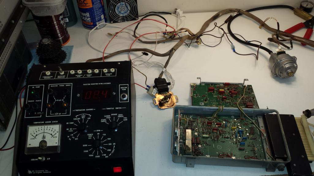
|
   |

 
|
Posts in this topic
pbanders D-Jet Bench Setup Nov 20 2015, 12:18 PM BeatNavy Brad, That's an awesome testing setup, and I l... Nov 20 2015, 01:15 PM Jeff Bowlsby Glad to see you back here and in the 914 Brad... Nov 20 2015, 02:24 PM r_towle Please find an electronic replacement for the MPS ... Nov 20 2015, 03:10 PM stugray Nice! That looks a lot like many of my various... Nov 20 2015, 06:28 PM
 pbanders
Nice! That looks a lot like many of my variou... Nov 20 2015, 07:18 PM Jeff Bowlsby Do it! Get 'er done! Keep the four p... Nov 20 2015, 06:46 PM pbanders I've posted in the past about the issues with ... Nov 20 2015, 07:08 PM Dave_Darling I've posted in the past about the issues with ... Nov 20 2015, 09:10 PM stugray
I've posted in the past about the issues with... Nov 21 2015, 01:37 PM pbanders
I've posted in the past about the issues wit... Nov 22 2015, 11:30 AM stugray Small world!
I have an arduino datalogger in ... Nov 20 2015, 07:39 PM pbanders
Small world!
I have an arduino datalogger in... Nov 20 2015, 07:41 PM pbanders
Nice! I just saw one of the big suppliers has... Nov 20 2015, 09:52 PM stugray
Nice! I just saw one of the big suppliers ha... Nov 21 2015, 02:29 PM Shredhead
ever since you explained how the MPS worked.
... Nov 20 2015, 09:49 PM pbanders
[quote name='Dave_Darling' post='2267680' date='N... Nov 20 2015, 09:54 PM pbanders Today's learning: The TPS uses a drag switch t... Nov 20 2015, 10:01 PM BeatNavy Brad - I've been chasing an issue (well, sever... Nov 21 2015, 07:32 AM Dave_Darling The best thing to do is to check the "idle... Nov 21 2015, 12:24 PM BeatNavy
The best thing to do is to check the "idle... Nov 22 2015, 10:55 AM Jeff Bowlsby The wire to the center cavity of the 5-pole TPS co... Nov 22 2015, 11:04 AM BeatNavy That would do it. I'll check again. Thanks J... Nov 22 2015, 11:06 AM pbanders stugray, which pressure sensor are you thinking of... Nov 22 2015, 11:36 AM pbanders
stugray, which pressure sensor are you thinking o... Nov 22 2015, 01:24 PM Tom Brad,
Did you get my PM from a day or so ago?... Nov 22 2015, 11:54 AM pbanders
Brad,
Did you get my PM from a day or so ago... Nov 22 2015, 01:30 PM worn
Brad,
Did you get my PM from a day or so ag... Nov 22 2015, 08:33 PM stugray
I've thought through the same thing, it shoul... Nov 22 2015, 12:22 PM pbanders
I've thought through the same thing, it shou... Nov 22 2015, 01:29 PM stugray
Out riding my bike and thinking - digital pressur... Nov 22 2015, 07:33 PM pbanders stugray, thanks, will let you know when I get to d... Nov 22 2015, 11:30 PM
pbanders
Nice! That looks a lot like many of my variou... Nov 20 2015, 07:18 PM Jeff Bowlsby Do it! Get 'er done! Keep the four p... Nov 20 2015, 06:46 PM pbanders I've posted in the past about the issues with ... Nov 20 2015, 07:08 PM Dave_Darling I've posted in the past about the issues with ... Nov 20 2015, 09:10 PM stugray
I've posted in the past about the issues with... Nov 21 2015, 01:37 PM pbanders
I've posted in the past about the issues wit... Nov 22 2015, 11:30 AM stugray Small world!
I have an arduino datalogger in ... Nov 20 2015, 07:39 PM pbanders
Small world!
I have an arduino datalogger in... Nov 20 2015, 07:41 PM pbanders
Nice! I just saw one of the big suppliers has... Nov 20 2015, 09:52 PM stugray
Nice! I just saw one of the big suppliers ha... Nov 21 2015, 02:29 PM Shredhead
ever since you explained how the MPS worked.
... Nov 20 2015, 09:49 PM pbanders
[quote name='Dave_Darling' post='2267680' date='N... Nov 20 2015, 09:54 PM pbanders Today's learning: The TPS uses a drag switch t... Nov 20 2015, 10:01 PM BeatNavy Brad - I've been chasing an issue (well, sever... Nov 21 2015, 07:32 AM Dave_Darling The best thing to do is to check the "idle... Nov 21 2015, 12:24 PM BeatNavy
The best thing to do is to check the "idle... Nov 22 2015, 10:55 AM Jeff Bowlsby The wire to the center cavity of the 5-pole TPS co... Nov 22 2015, 11:04 AM BeatNavy That would do it. I'll check again. Thanks J... Nov 22 2015, 11:06 AM pbanders stugray, which pressure sensor are you thinking of... Nov 22 2015, 11:36 AM pbanders
stugray, which pressure sensor are you thinking o... Nov 22 2015, 01:24 PM Tom Brad,
Did you get my PM from a day or so ago?... Nov 22 2015, 11:54 AM pbanders
Brad,
Did you get my PM from a day or so ago... Nov 22 2015, 01:30 PM worn
Brad,
Did you get my PM from a day or so ag... Nov 22 2015, 08:33 PM stugray
I've thought through the same thing, it shoul... Nov 22 2015, 12:22 PM pbanders
I've thought through the same thing, it shou... Nov 22 2015, 01:29 PM stugray
Out riding my bike and thinking - digital pressur... Nov 22 2015, 07:33 PM pbanders stugray, thanks, will let you know when I get to d... Nov 22 2015, 11:30 PM  |
1 User(s) are reading this topic (1 Guests and 0 Anonymous Users)
0 Members:

|
Lo-Fi Version | Time is now: 30th May 2026 - 05:56 AM |
Invision Power Board
v9.1.4 © 2026 IPS, Inc.