|
|
|
Porsche, and the Porsche crest are registered trademarks of Dr. Ing. h.c. F. Porsche AG.
This site is not affiliated with Porsche in any way. Its only purpose is to provide an online forum for car enthusiasts. All other trademarks are property of their respective owners. |
|
|

  |

| 913B |
 Feb 21 2016, 08:16 PM Feb 21 2016, 08:16 PM
Post
#1
|
|
Senior Member  Group: Members Posts: 847 Joined: 25-April 05 From: South Bay/SoCal Member No.: 3,983 Region Association: None |
I am in the midst of chasing why my hi beams inop condition. I have realized since the wiring was spliced in the pins might be incorrect in the 12pin connector. I have spent my whole Sunday and finally figured the pin were indeed in the wrong cavity. The solved that and now it triggers the relay I can get high beams.
The question is the gray spade wire on both sides of the column, I had it connected together but I am not sure if this is correct. The left is bigger gauge with a plastic cover it while the left side is smaller gauge and old connector has been cut off. I have read the right side one is for key buzzer ? So when does the buzzer come on and do I even want to re-connect that anyways. I happen to have another igntion column but it was a 14 pin connector but at least I can use it for some reference and look what I see the similiar set of grey wires and they were connected. Can someone educate me what these wires are for, are they supposed to connected where are they supposed to be connected to ?? Thanks in advance. Ted 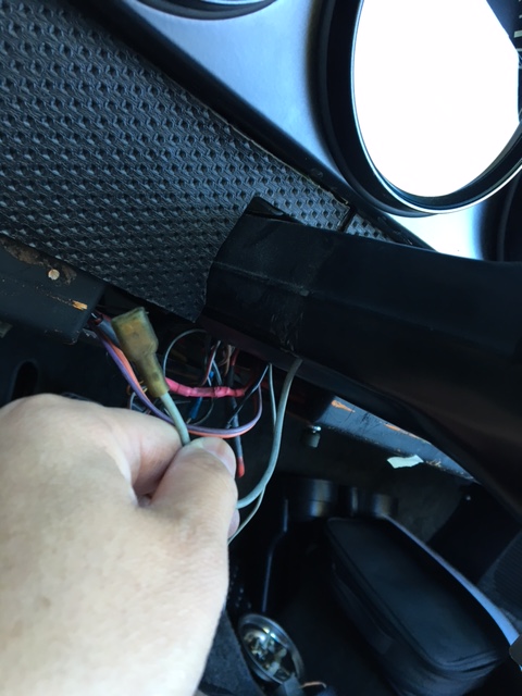 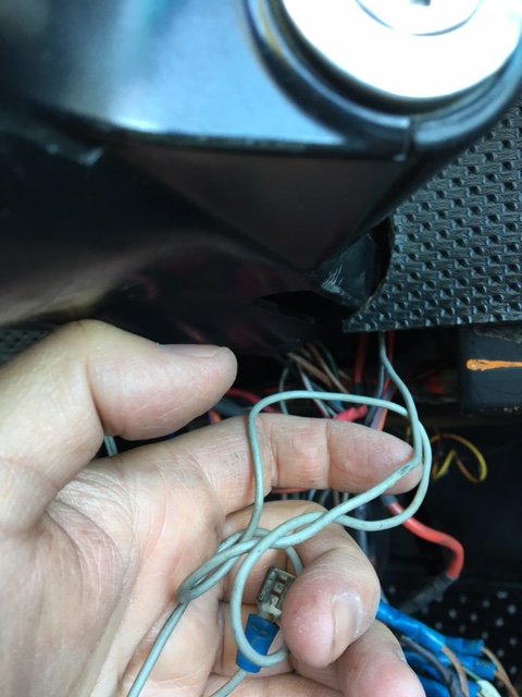 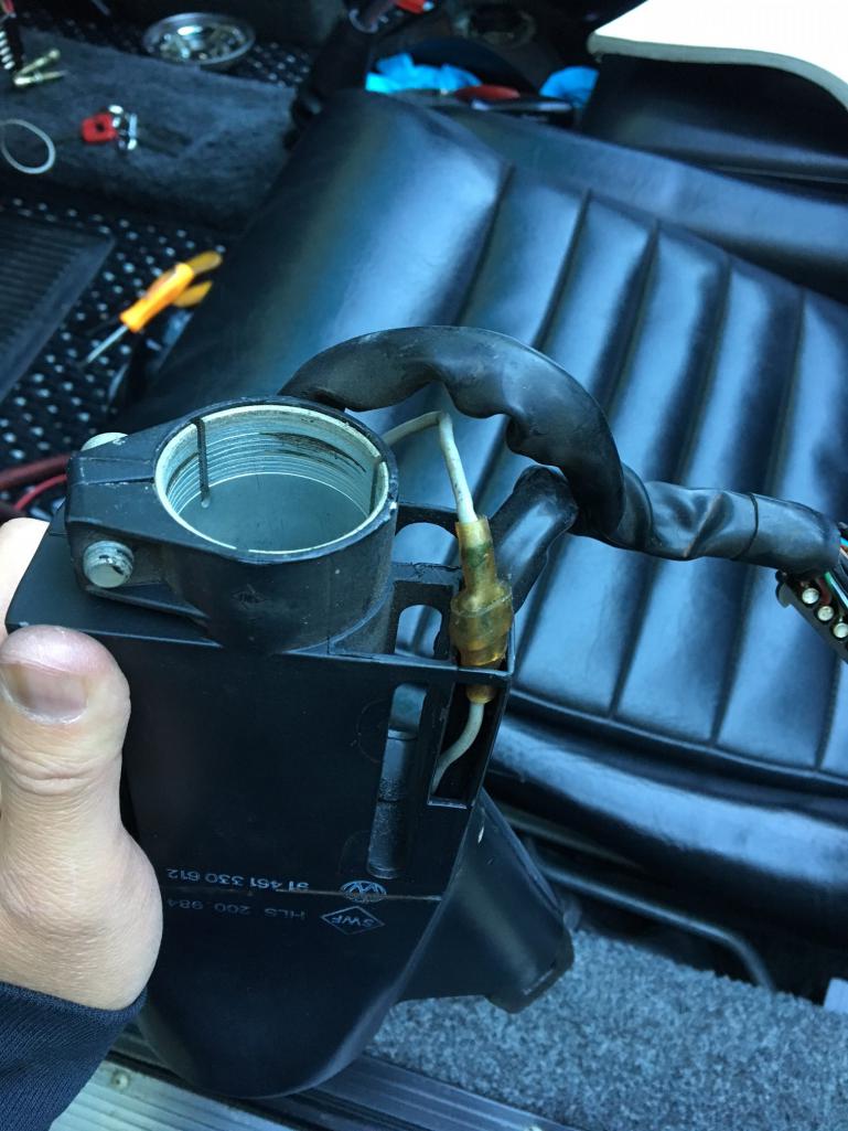 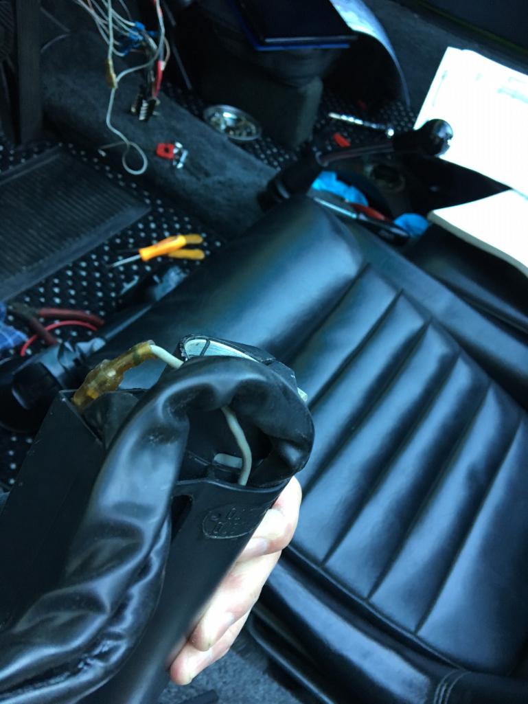 |
   |

 
|
| JeffBowlsby |
Feb 21 2016, 08:29 PM
Post
#2
|
|
914 Wiring Harnesses Group: Members Posts: 8,510 Joined: 7-January 03 From: San Ramon CA Member No.: 104 Region Association: None |
If I am reading the schematic correctly that grey connects the common of the ignition switch to the common of the L/R parking lights.
I would love to buy that 14 pin steering column from you (its a late 1971), or could trade a 12 pin correct for your car if you prefer. Let me know. |
 |
|
| 913B |
Feb 21 2016, 08:44 PM
Post
#3
|
|
Senior Member Group: Members Posts: 847 Joined: 25-April 05 From: South Bay/SoCal Member No.: 3,983 Region Association: None |
I have been racking my brain trying to understand the pin layout and symbols of the wiring diargram, some of them are incorrect which lead me to literally ohmming out the wires from end to end to figure which ones go where.
I got the color pelican diagram printed, the Haynes manual and the Prospero's color diagram. Jeff, you restoring an early car ? Whats the condition of the 12 pin column ? |
|
|
|
| 913B |
Feb 21 2016, 08:53 PM
Post
#4
|
|
Senior Member Group: Members Posts: 847 Joined: 25-April 05 From: South Bay/SoCal Member No.: 3,983 Region Association: None |
QUOTE(Jeff Bowlsby @ Feb 21 2016, 07:29 PM)  If I am reading the schematic correctly that grey connects the common of the ignition switch to the common of the L/R parking lights. I would love to buy that 14 pin steering column from you (its a let 1971), or could trade a 12 pin correct for your car if you prefer. Let me know. I had the gray wire disconnected and the parking and directional lights still worked though. (IMG:style_emoticons/default/confused24.gif) (IMG:style_emoticons/default/confused24.gif) |
|
|
|
| JeffBowlsby |
Feb 21 2016, 09:09 PM
Post
#5
|
|
914 Wiring Harnesses Group: Members Posts: 8,510 Joined: 7-January 03 From: San Ramon CA Member No.: 104 Region Association: None |
Compare these if they help.
The two color schemtics are the factory 1971, should be the 14-pin. The black/white is the 1970 12-pin. See how they are the same/different. The Xl sheet is a comparison I did awhile ago, not 100% sure its accurate. Would be interested to know what you find and to make any needed corrections. PS, my 12-pin column is in good condition, can send photos if you PM me your email Attached thumbnail(s) 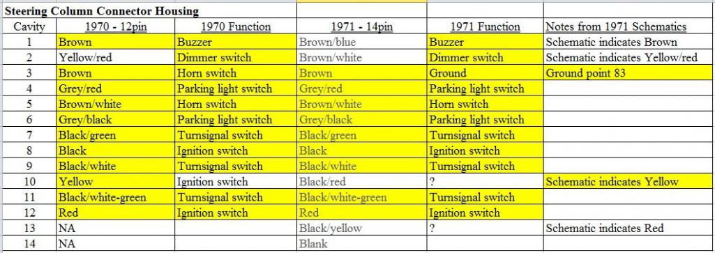 Attached image(s) 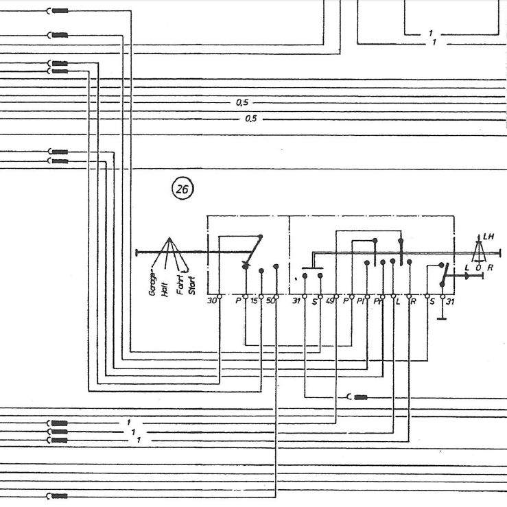 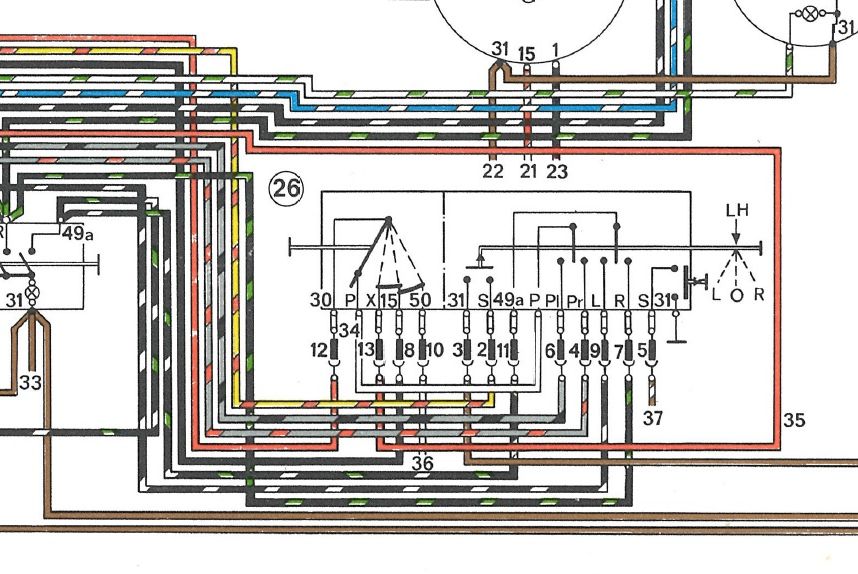 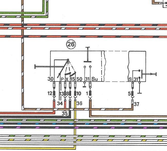
|
|
|
|
| 913B |
Feb 21 2016, 09:30 PM
Post
#6
|
|
Senior Member Group: Members Posts: 847 Joined: 25-April 05 From: South Bay/SoCal Member No.: 3,983 Region Association: None |
That black white is tough to understand without color codes, where can I get more details of the 12 pin 1970 schematic. The Haynes and color diagrams dont mention if 12/14 pin connector. I guess you would know more. (IMG:style_emoticons/default/biggrin.gif)
Will do on the inaccuracies (IMG:style_emoticons/default/first.gif) PM coming. Thanks |
|
|
|
| 913B |
Feb 21 2016, 09:37 PM
Post
#7
|
|
Senior Member Group: Members Posts: 847 Joined: 25-April 05 From: South Bay/SoCal Member No.: 3,983 Region Association: None |
On the color diagrams, what does the top row of number/lettering supposed to represent, the pin out from the horn/ign switch/turn signal stalk and such ?
|
|
|
|
| JeffBowlsby |
Feb 21 2016, 11:16 PM
Post
#8
|
|
914 Wiring Harnesses Group: Members Posts: 8,510 Joined: 7-January 03 From: San Ramon CA Member No.: 104 Region Association: None |
The B/W diagram IS from the only 1970 schematic. It came in the Service and training manuals - its not in Haynes or the FWSM. Youc an get through it if you study it.
Reference the color late 1971 version for the colors of the same circuits. That upper row of letters should index to the ignition switch body and turnsignal switch body. The rectangular bar symbol is the connection between the column and the 12/14 pin connector - referenced to their numbered cavities. |
|
|
|
| pdlightning |
Feb 24 2016, 09:54 PM
Post
#9
|
|
Member Group: Members Posts: 207 Joined: 4-February 11 From: Santa Clarita Member No.: 12,660 Region Association: Southern California |
QUOTE(Jeff Bowlsby @ Feb 21 2016, 09:16 PM) The B/W diagram IS from the only 1970 schematic. It came in the Service and training manuals - its not in Haynes or the FWSM. Youc an get through it if you study it. Reference the color late 1971 version for the colors of the same circuits. That upper row of letters should index to the ignition switch body and turnsignal switch body. The rectangular bar symbol is the connection between the column and the 12/14 pin connector - referenced to their numbered cavities. What about the later columns? Does the 73 have the 12 or 14 pin connector? |
|
|
|
| JeffBowlsby |
Feb 25 2016, 11:42 AM
Post
#10
|
|
914 Wiring Harnesses Group: Members Posts: 8,510 Joined: 7-January 03 From: San Ramon CA Member No.: 104 Region Association: None |
No, the 1972-76 are completely different. They have 2 connectors and are configured differently.
|
|
|
|
|
1 User(s) are reading this topic (1 Guests and 0 Anonymous Users)
0 Members:

|
Lo-Fi Version | Time is now: 17th May 2024 - 08:36 PM |
Invision Power Board
v9.1.4 © 2024 IPS, Inc.