|
|
|
Porsche, and the Porsche crest are registered trademarks of Dr. Ing. h.c. F. Porsche AG.
This site is not affiliated with Porsche in any way. Its only purpose is to provide an online forum for car enthusiasts. All other trademarks are property of their respective owners. |
|
|


| doug_b_928 |
 Jan 31 2018, 03:55 PM Jan 31 2018, 03:55 PM
Post
#1
|
|
Senior Member  Group: Members Posts: 714 Joined: 17-January 13 From: Winnipeg Member No.: 15,382 Region Association: Canada |
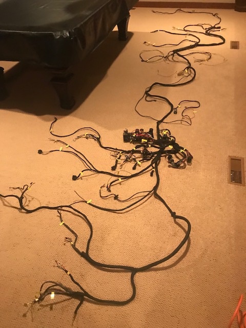
My main Winter project is to 'restore' the wiring harness on my 73. I admit that of all the jobs involved in restoring this car, this is the one that creates the most anxiety in me. I took it out of it's container last winter, spread it out on the floor, and promptly proceeded to put it back in the container. But, the time has come to conquer this thing. I have 4 rolls of wire tape that cost more to ship to me than the tape itself, and I think everything I need to do the job. I have pieces of a 74 harness (which I'm aware is not the same) and have already used one of the correct connectors from it for one of the license plate light connectors. Overall, I think the harness could be a lot worse, but there are some areas where POs have made some modifications/fixes and I'm not sure what they've done and why. I'll be asking for assistance from the wiring gurus in the thread as I work my way through. I have the wiring diagram from Jeff Bowlsby's website, a multimeter, PowerProbe3, and cleaning supplies. I'm removing all the tape, inspecting, cleaning, and then installing new tape. I'm just going to clean and inspect the rubber covered sheaths as they seem to be tight around the wires and it seems unlikely that there is anything wrong underneath them (on the upside, everything that ever worked on the car during my ownership, which wasn't everything that was supposed to, still did right before I removed the harness).
Okay, so with that introduction, my first questions. Starting at the back, I've worked my way through the license plate wires, to the trunk light wires, and I'm currently looking at the fuel pump wires. My car had vapor lock, so the fuel pump was relocated to the front of the car. The mechanic just cut the wires, left the ground wire dangling, and spliced in a positive wire which he ran through the firewall (poking a hole; no grommet), under the carpet and through a hole in the front firewall, where he then spliced in the connector and grounded to a screw he added to the front firewall. Here's a pic of the wires: 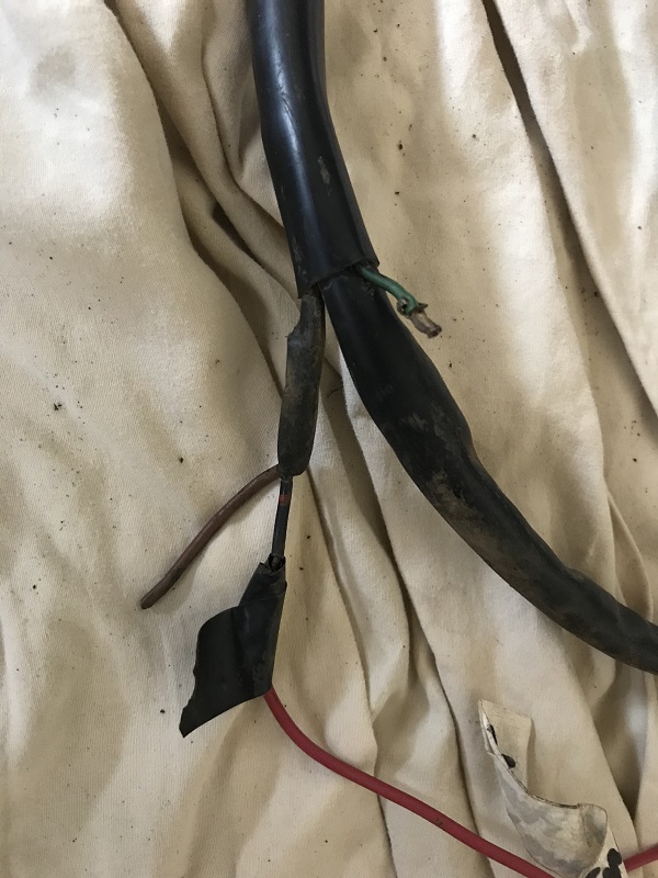 Because of the vapor lock issue, I'm thinking I should put my new pump in the front where the old one was (by the steering rack). I'm thinking of getting the NAPA Bosch fuel pump (N69133). From what I can tell looking at the wiring diagram, and I could be reading it wrong, the power wire goes to the 'regulator/relay plate). If it's source was at the fuse box under the dash I'd splice into the wire up there and put the original connector back on the wires in the engine bay (in case I ever wanted to put an original style in its original spot. If I'm correct about the wiring diagram, then, with my limited knowledge, I guess I have to run the power wire on the outside of the sheath (but at least it will be inside the new 914 rubber snorkel) and up to the fuel pump in the front? Is there any point in running the ground wire that way too, or would you just ground it to a screw on the car as it was before? Also, in the pic above there is a green wire that looks like it had a connector on it at one time. Does anyone know what that was for? When I look at the 73 diagram it only shows the black with red dots and the ground for the fuel pump. On the diagram it shows the, IIRC, 'fan blower motor' having a green wire. However, if that's referring to the blower motor for the heater, I think the wires and connector below were for that (note no green wire). 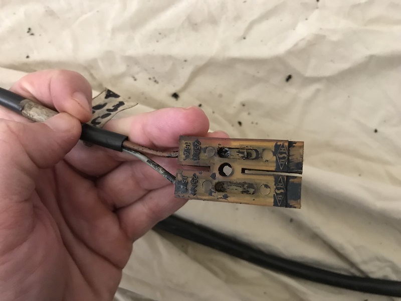 So, to summarize, what's the best approach for the fuel pump wiring, and what is that green wire for? |
   |

 
|
  |
Replies(60 - 78)
| bbrock |
Feb 21 2018, 07:45 PM
Post
#61
|
|
914 Guru Group: Members Posts: 5,269 Joined: 17-February 17 From: Montana Member No.: 20,845 Region Association: Rocky Mountains |
QUOTE(doug_b_928 @ Feb 21 2018, 05:46 PM)  I just searched some old pictures and it appears the modified wiring originally looked more like this? So, it looks like fuse 12 (on the direct connection to battery side) was wired to an inline fuse that then went to the fuse 8. Not sure why they did this. The antenna was powered from fuse 11 And probably the radio was powered from fuse 10... So, to instead of figuring out what the PO had done, again, the best way to ask is, what is the correct/best way to wire in power for the antenna and radio? Yeah, it's ugly to say the least. For starters, I'd put female spades on the radio and antenna wires and slide them onto the back of the fuse panel the proper way. There are several slots that have extra lugs for plugging in extras both before and after the fuse in the panel. I don't understand the jumper between fuse 12 and 8. Seems like a bad idea. Somewhere I thought I ran across which fuse the factory radio harnesses plugged into, but for the life of me can't remember where, nor whether a modern radio would draw more power than whatever the factory or dealer would have installed. If nobody comes to the rescue with an answer, I'd be inclined to leave the inline fused in place, and plug them into whichever fuse has the fattest wire coming from the battery and an extra lug BEFORE the fuse. That way the radio and antenna would be protected with the inline fuses without running current through the fuse on the panel and possibly overloading it. I've never had an automatic antenna, but can't imagine they draw much power and how often are they operating anyway? I'd be inclined to twist the radio and antenna wires together and crimp a single female spade on the pair. Now let's see if Jeff or anyone jumps in to point out how full of (IMG:style_emoticons/default/stromberg.gif) I am. (IMG:style_emoticons/default/biggrin.gif) |
|
|
|
| doug_b_928 |
Feb 23 2018, 07:44 PM
Post
#62
|
|
Senior Member Group: Members Posts: 714 Joined: 17-January 13 From: Winnipeg Member No.: 15,382 Region Association: Canada |
Thanks very much Brent. Yeah, after all of this I definitely want to have a more professional installation. How do I know which terminals on the fuse panel are switched with the ignition?
Other outstanding issues: 1. I still don't know how to connect the wires to the combination relay (as outlined in my post above). 2. I don't yet know what radio I'll get (probably something that looks somewhat period correct but that will allow blue tooth etc), but do most have a power wire for the antenna or is that a separate power going directly from the fuse panel to the antenna? 3. A PO had installed an electric motor for the WW fluid. I understand that originally it would have had a pump that ran off of the air in the spare tire. I'd like to go back to original (this car will be a fair weather driver so electric pump is not necessary). 4. Where was the original button to activate the WW fluid? 5. Also, is the pump pictured below the original pump? 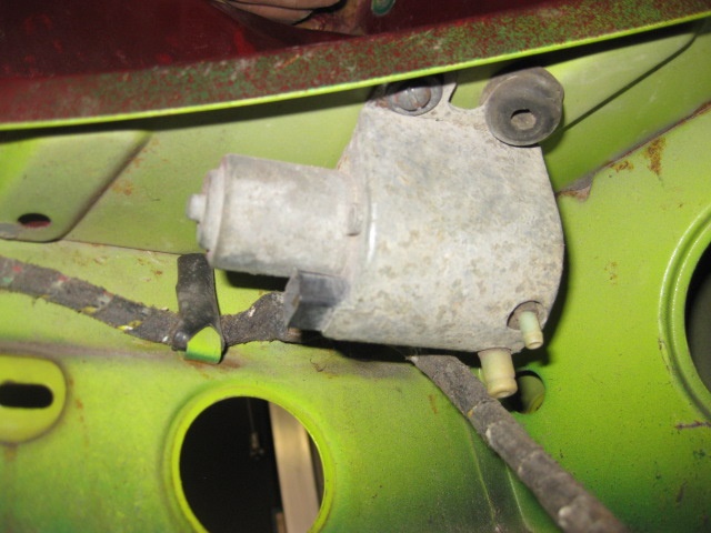 |
|
|
|
| doug_b_928 |
Feb 23 2018, 07:58 PM
Post
#63
|
|
Senior Member Group: Members Posts: 714 Joined: 17-January 13 From: Winnipeg Member No.: 15,382 Region Association: Canada |
Did a little searching and see that there was not washer pump at all originally. I'm guessing what's pictured above was someone's solution to the spare tire pump?
|
|
|
|
| JeffBowlsby |
Feb 23 2018, 08:05 PM
Post
#64
|
|
914 Wiring Harnesses & Beekeeper Group: Members Posts: 8,978 Joined: 7-January 03 From: San Ramon CA Member No.: 104 Region Association: None |
If my memory is right the radio clips to Fuse #7 but need to confirm.
That pump looks like it might be the pump for the factory headlight squirter system. If so its golden. Do you have any other parts to that system such as the squirters on the front rubber bumper pad? Attached File(s)  wwpump.pdf ( 94.27k )
Number of downloads: 677
wwpump.pdf ( 94.27k )
Number of downloads: 677 |
 |
|
| doug_b_928 |
Feb 23 2018, 08:41 PM
Post
#65
|
|
Senior Member Group: Members Posts: 714 Joined: 17-January 13 From: Winnipeg Member No.: 15,382 Region Association: Canada |
Thanks very much as always Jeff. I'll await your confirmation for which fuse to go to for the radio and antenna. Is there a gauge that is best for radios?
I'm thinking now's the time to run wires for an electric washer in case I decide to go that route. The POs method was not pretty. Do you have a recommendation as to what to do to be 'electric WW motor ready' (e.g., where to run the wires, how many, what gauge, etc.)? I don't recall any other parts as shown in the diagram you attached. Certainly no outlets on the front bumper top, but I suppose that could have been changed though I don't know why since the car is unbent on the front. |
|
|
|
| JeffBowlsby |
Feb 23 2018, 08:56 PM
Post
#66
|
|
914 Wiring Harnesses & Beekeeper Group: Members Posts: 8,978 Joined: 7-January 03 From: San Ramon CA Member No.: 104 Region Association: None |
I know I have seen a harness with the radio at fuse 7, but also found this from the Dr.:
"the factory source was the cigar lighter Many though have tapped the second or third fuse over from the passenger right side so that they could operate the radio without having to turn the key on" |
|
|
|
| doug_b_928 |
Feb 23 2018, 09:01 PM
Post
#67
|
|
Senior Member Group: Members Posts: 714 Joined: 17-January 13 From: Winnipeg Member No.: 15,382 Region Association: Canada |
Thanks again Jeff!
As an update, here's a before and after of the fuse panel. It occurred to me that the labels might be an issue. I checked them for continuity and nothing. I assume that means they won't conduct electricity. But are they a fire hazard somehow? Any chance you can make sense of the connectors on the combination relay above? 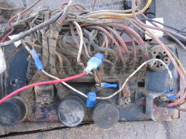 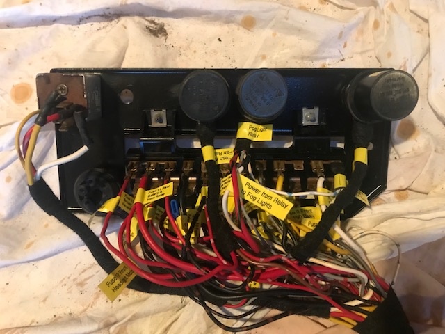 |
|
|
|
| JeffBowlsby |
Feb 23 2018, 09:44 PM
Post
#68
|
|
914 Wiring Harnesses & Beekeeper Group: Members Posts: 8,978 Joined: 7-January 03 From: San Ramon CA Member No.: 104 Region Association: None |
Looks good. Hope you see now why I don't recondition these chassis harnesses.
Attached image(s) 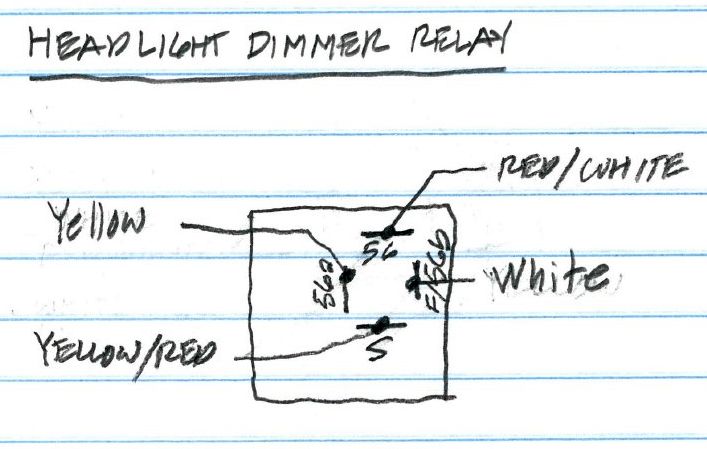
|
|
|
|
| doug_b_928 |
Feb 23 2018, 09:49 PM
Post
#69
|
|
Senior Member Group: Members Posts: 714 Joined: 17-January 13 From: Winnipeg Member No.: 15,382 Region Association: Canada |
Thanks Jeff. So to make sure, no fire issues with the labels? I chuckled with your comment because several times I have thought to myself “now I know why Jeff doesn’t do full harnesses anymore!”
|
|
|
|
| JeffBowlsby |
Feb 23 2018, 10:10 PM
Post
#70
|
|
914 Wiring Harnesses & Beekeeper Group: Members Posts: 8,978 Joined: 7-January 03 From: San Ramon CA Member No.: 104 Region Association: None |
I would not label them permanently, but I see no harm.
|
|
|
|
| doug_b_928 |
Feb 23 2018, 10:16 PM
Post
#71
|
|
Senior Member Group: Members Posts: 714 Joined: 17-January 13 From: Winnipeg Member No.: 15,382 Region Association: Canada |
Excellent, thanks Jeff. I'm leaving them for next time I have to go back in there (Don't want to have to through all that again if I can help it).
|
|
|
|
| bbrock |
Feb 23 2018, 11:49 PM
Post
#72
|
|
914 Guru Group: Members Posts: 5,269 Joined: 17-February 17 From: Montana Member No.: 20,845 Region Association: Rocky Mountains |
QUOTE(doug_b_928 @ Feb 23 2018, 06:44 PM) 3. A PO had installed an electric motor for the WW fluid. I understand that originally it would have had a pump that ran off of the air in the spare tire. I'd like to go back to original (this car will be a fair weather driver so electric pump is not necessary). (IMG:style_emoticons/default/beerchug.gif) (IMG:style_emoticons/default/cheer.gif) I'm with you here. People like to "upgrade" to electric pumps, but I think the original system is pure genius and one of my favorite quirks on a car that has so many of them. As you discovered, there is no pump. Just a hose from the spare tire to the fluid bottle, another from the fluid bottle to the switch, and then from the switch to the nozzles. On a '73, the washer is activated by pulling back on the wiper lever. A couple things if you restore it. First, get the right hose. It is under pressure and regular washer tubing will burst and leave you with a wet lap. 914rubber had a bunch of hose kits, not sure if they still do. Second, the connector that screws to the tire has a valve in it to make sure you maintain enough pressure in the tire to use it as a spare. You fill the spare to the max pressure on the sidewall and when you get down to something like 25 lbs. it shuts off. Other than learning about the hose thing the wet way, I always thought the system worked beautifully even when teeners were out only cars for year round driving. Nice work on the fuse panel. I'm doing the same with the labels. I'm leaving them on until it is ready to go back in the car. |
|
|
|
| doug_b_928 |
Feb 24 2018, 05:46 AM
Post
#73
|
|
Senior Member Group: Members Posts: 714 Joined: 17-January 13 From: Winnipeg Member No.: 15,382 Region Association: Canada |
Thanks for WW fluid system explanation, Brent. Do you know if anyone sells a kit with everything to restore it?
I’m thinking I should still run a couple of wires (I’m guessing a positive and ground) for an electric pump just in case. Any thoughts as the appropriate gauge I should add? My plan is to leave the labels on the whole harness. It will make it easy for the next person in another 50 years. I’m also not leaving gaps between the tape. I think it looks nice that way but after all the work cleaning the wires (which were dirty where they were exposed) I’ll sleep better knowing they will stay clean; and again the next guy will appreciate that someday too (IMG:style_emoticons/default/smile.gif) |
|
|
|
| doug_b_928 |
Feb 24 2018, 10:05 AM
Post
#74
|
|
Senior Member Group: Members Posts: 714 Joined: 17-January 13 From: Winnipeg Member No.: 15,382 Region Association: Canada |
Update: I’ve added a couple pieces of wire (look like 16G) for power and ground to the WW pump so I have the option to go electric. I also see the black and brown wire for the intermittent wiper relay. From Sir Andy’s write-up in the tech section it looks to me though like the best way to power the washer is just use the brown/black wire for the intermittent wiper relay. Do I understand correctly that he relay is not needed, rather that wire gets power when the lever on the steering column is pulled (from the write-up it looks like he splices into that wire before the relay location)? Either way I’ll leave the added power wire as a backup.
|
|
|
|
| doug_b_928 |
Feb 24 2018, 02:35 PM
Post
#75
|
|
Senior Member Group: Members Posts: 714 Joined: 17-January 13 From: Winnipeg Member No.: 15,382 Region Association: Canada |
Technical question: the small black with blue wire that gives power to the gauge cluster lights was spanning from the gauges to the fresh air controls from outside the taped harness. It is originally that way, at least for this harness. It would be so much neater to make it a little longer (about 18” at most) and have it follow the loom for the fresh air instead of being a wire on its own getting tangled spanning two branches of the main harness. I measured he resistance in its original configuration as 14 ohms. Then I cut it and spliced in a piece and then rechecked the resistance, finding it to be 24 ohms. I realize that the longer the wire the greater the resistance. But that got me wondering if the factory had it that way to avoid problems with it being a bit longer. Will that change in length of a small wire create any problems?
|
|
|
|
| doug_b_928 |
Feb 25 2018, 10:19 PM
Post
#76
|
|
Senior Member Group: Members Posts: 714 Joined: 17-January 13 From: Winnipeg Member No.: 15,382 Region Association: Canada |
Winter job done (with the exceptions of needing to solder back on the original fuel pump connector once I bring it out of storage, new snorkel, and adding terminals for the new fuel pump and WW wires once I have them trimmed to the correct length). I just wanted to say thanks to all who have replied to my questions in this thread. Your assistance gave me the confidence to get through what I felt would be the most intimidating job of this entire restoration. Also, if anyone who reads this thread has answers to the unanswered questions above, please reply as I'd still like to know the answers. Here's the pic of the final product...
 |
|
|
|
| bbrock |
Feb 25 2018, 11:18 PM
Post
#77
|
|
914 Guru Group: Members Posts: 5,269 Joined: 17-February 17 From: Montana Member No.: 20,845 Region Association: Rocky Mountains |
|
|
|
|
| doug_b_928 |
Feb 26 2018, 08:47 AM
Post
#78
|
|
Senior Member Group: Members Posts: 714 Joined: 17-January 13 From: Winnipeg Member No.: 15,382 Region Association: Canada |
Thanks Brent. There are two questions that I forgot to ask that are still bugging me a bit:
1. In the wiring for the Fuel Gauge (shown below), there is a brown with white wire that exits and goes through a diode, and from the diode it branches into two wires going to the safety belt warning light and the parking break contact. I could not get continuity through those wires. I removed the diode and could not get continuity through it. I did a little searching and could not see whether or not there should be continuity thorough a diode. But I assumed not. Should there be? Per what I read I tested the resistance in both directions and found different readings in each direction which indicated the diode is good. I'd like to know for sure if it's good before installing the harness back in the car. Is there anything else I should do? 2. The Turn Signal/Emergency Flasher Unit looks like a relay, but the pins are not marked the same as the other relays and when I looked for continuity across any two pins I could not find it. I have a spare from the parts harness and it behaved the same. Is this unit a relay or something else? 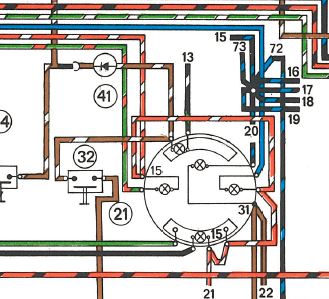 |
|
|
|
| doug_b_928 |
Feb 26 2018, 10:19 AM
Post
#79
|
|
Senior Member Group: Members Posts: 714 Joined: 17-January 13 From: Winnipeg Member No.: 15,382 Region Association: Canada |
Update re testing a diode: I found this youtube video which explains it well. My diode tested at .560 in 1 direction and OL in the other, so hopefully that means it's good (IMG:style_emoticons/default/smile.gif).
https://www.youtube.com/watch?v=qSDRsz5-t7I...lay=1&rel=0 |
|
|
|
|
1 User(s) are reading this topic (1 Guests and 0 Anonymous Users)
0 Members:

|
Lo-Fi Version | Time is now: 16th July 2025 - 07:12 PM |
Invision Power Board
v9.1.4 © 2025 IPS, Inc.