|
|
|
Porsche, and the Porsche crest are registered trademarks of Dr. Ing. h.c. F. Porsche AG.
This site is not affiliated with Porsche in any way. Its only purpose is to provide an online forum for car enthusiasts. All other trademarks are property of their respective owners. |
|
|

  |

| Spoke |
 Apr 26 2018, 10:47 PM Apr 26 2018, 10:47 PM
Post
#1
|
|
Jerry  Group: Members Posts: 6,977 Joined: 29-October 04 From: Allentown, PA Member No.: 3,031 Region Association: None |
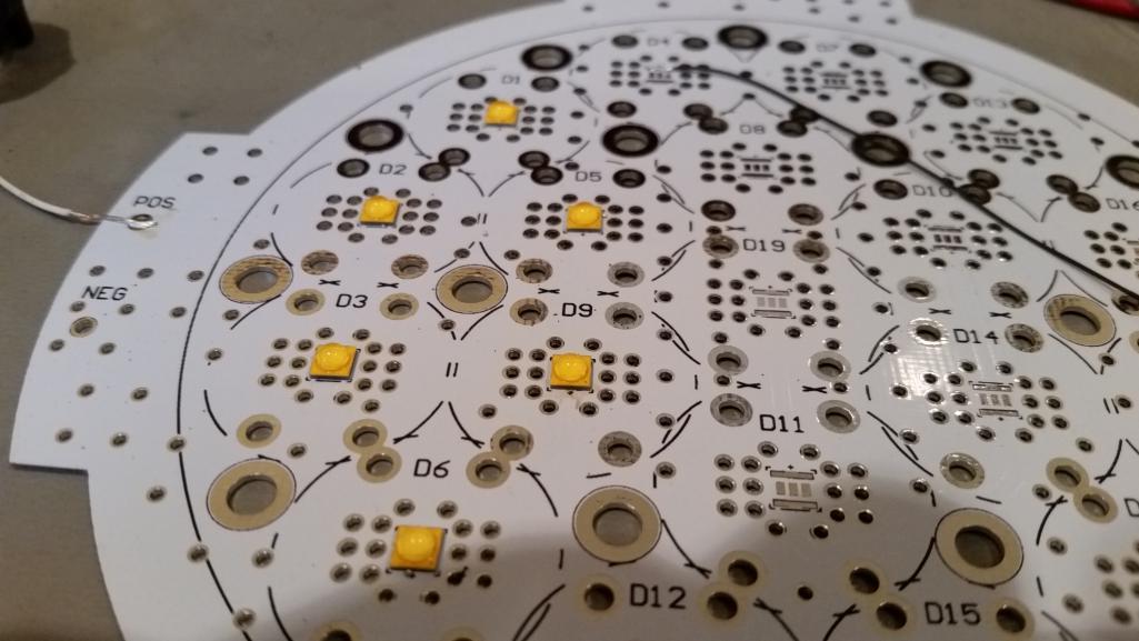
A Porsche 356 owner contacted me about converting a set of Marchal fog running lights to LEDs. We talked about it and he asked if I could do it in 6 weeks. My response was I've never done a high power LED headlamp so it's more of a project than a product. The Marchal running light is shown on this file-folder picture of a 356. That's not me nor the owner. (IMG:style_emoticons/default/smile.gif) 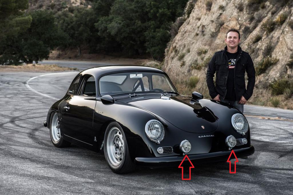 The idea was to design an LED-only board attached to a large heat sink and use a step-up dc-dc converter on a separate board to provide 0.275Amp to the LEDs. The LEDs are Cree XP-G3 surface mount LEDs. These have a maximum current of 2 amps. The LEDs require a lens to focus the light pattern. The XP-G3 have a wide output light pattern and can't be used 'naked'. The lens per LED are Carclo's 10049 lens with a light pattern shown below. 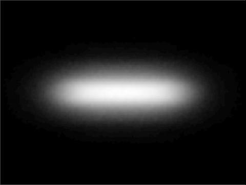 The LED board uses 19 LEDs with lenses and holders. The board will be backed by a very large heat sink. The main killer of LEDs is heat. 2 amps through an LED with 3.5V is 7W in less than 1/4" square area. Massive power dissipation/heat in a very small area. The PCB really should be an aluminum PCB but they are really expensive so the PCB is FR4 and is thin at 0.8mm to minimize thermal impedance of FR4. Vias from top to bottom are liberally applied to provide as much metal top-to-bottom for heat transfer. The clear area of the bottom of the board will allow maximum heat flow to the heat sink. 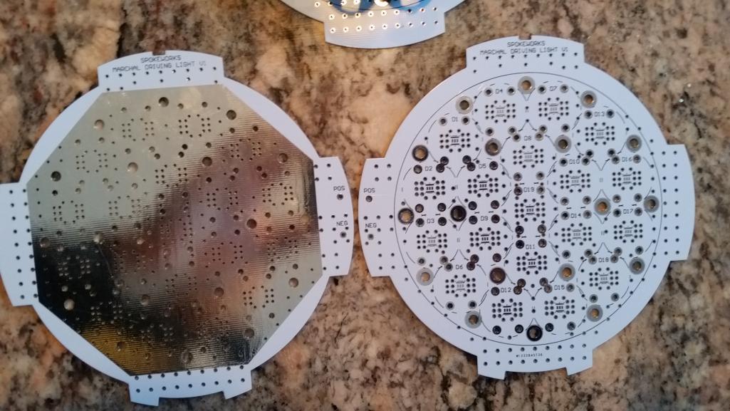 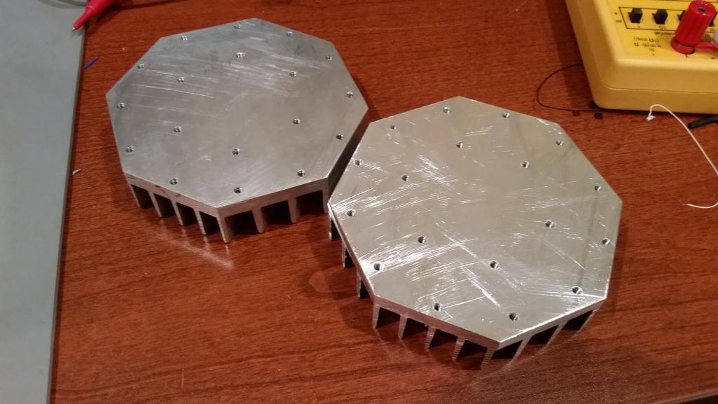 |
   |

 
|
| Spoke |
Apr 26 2018, 11:44 PM
Post
#2
|
|
Jerry Group: Members Posts: 6,977 Joined: 29-October 04 From: Allentown, PA Member No.: 3,031 Region Association: None |
Here's a picture of the XP-G3 LEDs as they were soldered in place. I did 3 at a time to make sure they worked. Had to use a heat gun to solder; hold the LED with tweezers; wait for the solder on the PCB to melt,; place the LED; wait for the solder to melt around the LED; remove heat; wait to cool: 1 LED placed. Not too much fun.
 Here's the first 6 LEDs lit up with their respective lenses. This is running about 0.3 amps. Couldn't light them too long because of temperature rise without the heat sink attached. 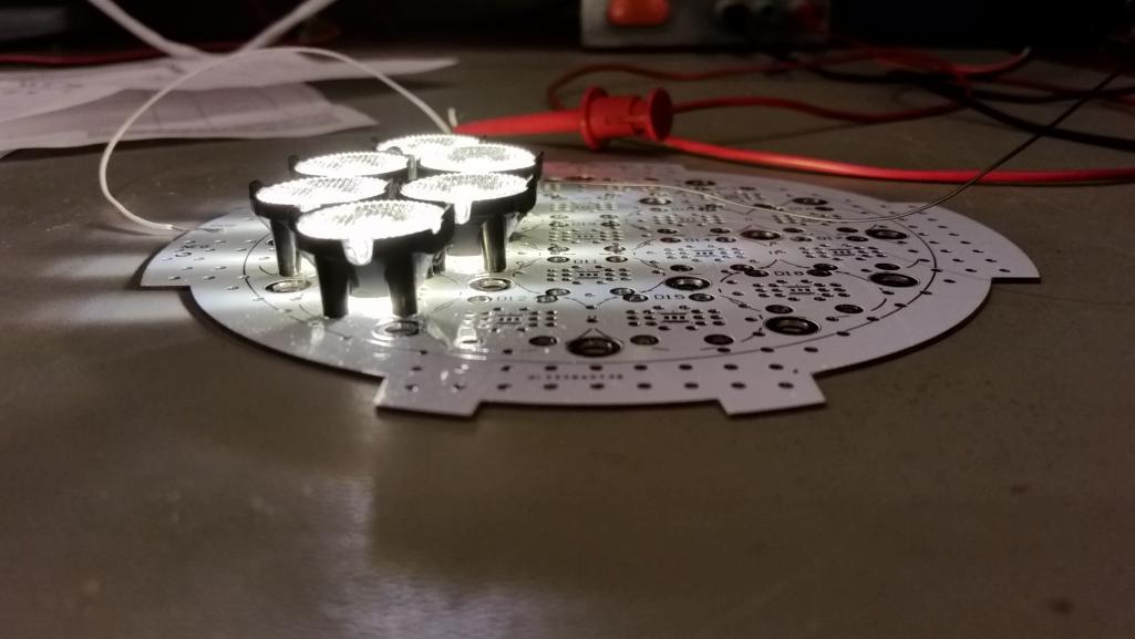 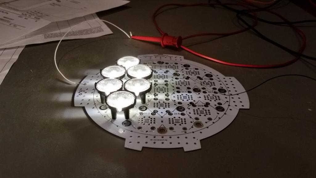 |
|
|
|
| EdwardBlume |
Apr 27 2018, 04:18 AM
Post
#3
|
|
914 Wizard Group: Members Posts: 12,338 Joined: 2-January 03 From: SLO Member No.: 81 Region Association: Central California |
Looks good. (IMG:style_emoticons/default/aktion035.gif)
|
|
|
|
| mepstein |
Apr 27 2018, 04:52 AM
Post
#4
|
|
914-6 GT in waiting Group: Members Posts: 19,244 Joined: 19-September 09 From: Landenberg, PA/Wilmington, DE Member No.: 10,825 Region Association: MidAtlantic Region |
Love the black 356!
I put Spoke's lights on all my cars. |
|
|
|
| JmuRiz |
Apr 27 2018, 07:03 AM
Post
#5
|
|
914 Guru Group: Members Posts: 5,424 Joined: 30-December 02 From: NoVA Member No.: 50 Region Association: MidAtlantic Region |
Cool project!
|
|
|
|
| Coondog |
Apr 27 2018, 07:15 AM
Post
#6
|
|
Advanced Member Group: Members Posts: 2,089 Joined: 24-September 15 From: Apple Valley Calif Member No.: 19,195 Region Association: Southern California |
Great job. I have said it a thousand times.
Your Led lights should be the first mod every 914 owner makes...... |
|
|
|
| Spoke |
Apr 27 2018, 07:59 AM
Post
#7
|
|
Jerry Group: Members Posts: 6,977 Joined: 29-October 04 From: Allentown, PA Member No.: 3,031 Region Association: None |
This was the first light-up of the full 19 LED lamp. Here I'm running 0.35 amps through each LED.
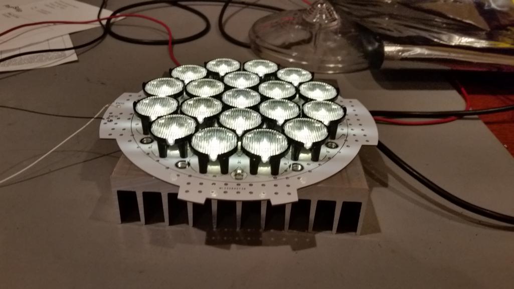 This is the light pattern on the ceiling 6 feet from the LEDs. Pretty much the same as the lens manufacturer stated. Unlike headlights these days, the lenses don't offer a sharp cutoff in the vertical direction. These lamps will likely need to be pointed downward a bit to not blind oncoming traffic.  The LED board needed to be trimmed down a little to fit inside the bezel. The heatsink is a bit over 1 inch deep but still fits easily inside the case. 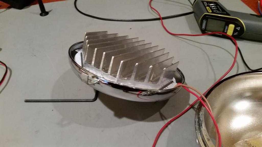 Getting the LED lenses and holders to fit under the glass was a chore. I had to place the LEDs so close to each other such that the holders overlapped each other by about 20 mil. Each holder had to be filed where they interfered with their neighbors. In the end it worked out ok. 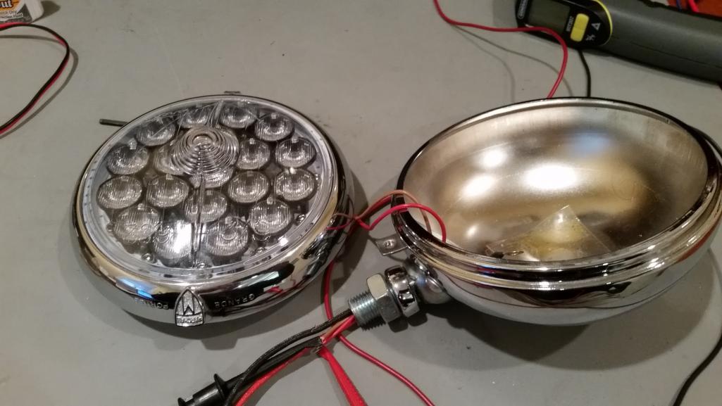 The LEDs look really cool when not lit. They are so bright when lit that you can't look directly into them. 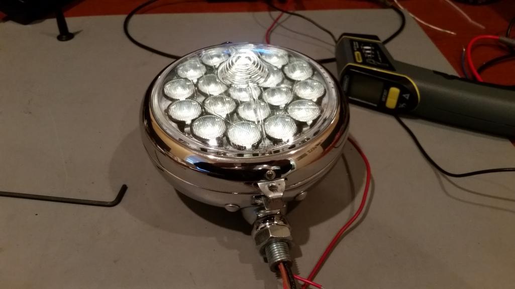 Here's the LED stack running 0.33 amps at 53V for a little over 17W dissipation. The step-up converter driving the LEDs is about 90% efficient so this lamp will burn about 20W and is a bit brighter than the low beams on my road car. 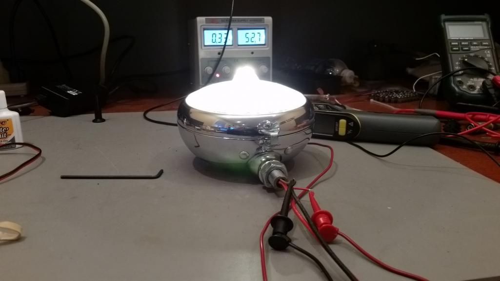 |
|
|
|
| Spoke |
Apr 27 2018, 09:15 PM
Post
#8
|
|
Jerry Group: Members Posts: 6,977 Joined: 29-October 04 From: Allentown, PA Member No.: 3,031 Region Association: None |
This is the first converter board driving the LED stack with 0.35 amps. Burning about 20W. The switching MOSFET was getting pretty hot. It was running about 75C which is 50C above ambient.
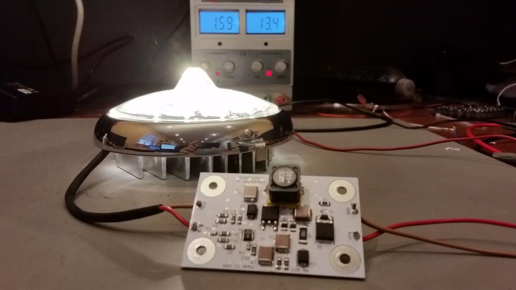 The converter board will be mounted behind the heatsink using extra long screws for the LED board. 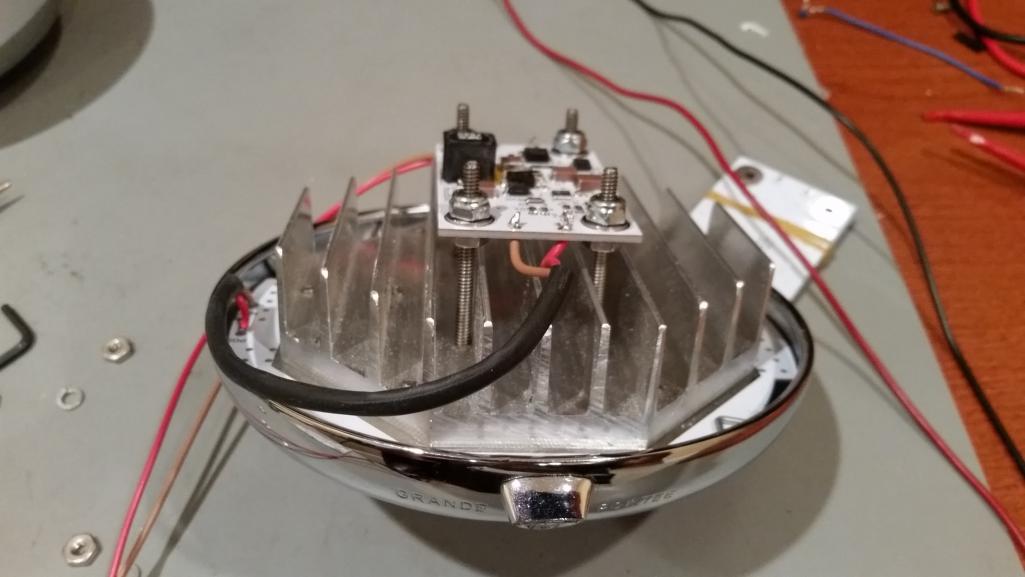 Once mounted on the heatsink, the added heat from the heatsink was enough to kill the MOSFET. Didn't do the PCB any favors either as it became a molten pile of silicon. Pretty much stunk up the office with that burnt electronics smell. Everyone who came in wanted to know what burned. 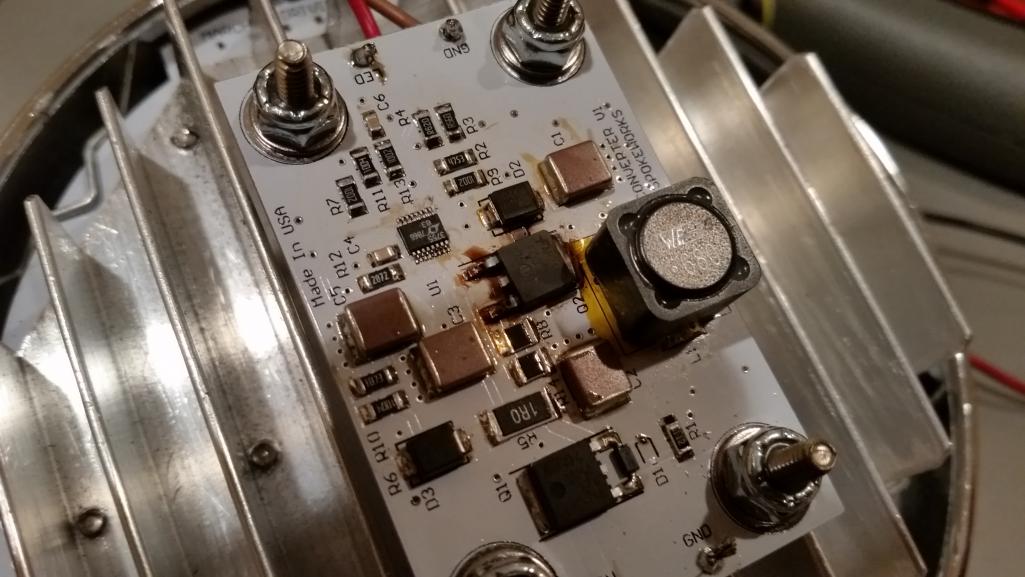 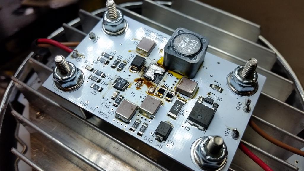 |
|
|
|
| Chris914n6 |
Apr 28 2018, 01:33 PM
Post
#9
|
|
Jackstands are my life. Group: Members Posts: 3,305 Joined: 14-March 03 From: Las Vegas, NV Member No.: 431 Region Association: Southwest Region |
QUOTE(Spoke @ Apr 27 2018, 06:59 AM)  This is the light pattern on the ceiling 6 feet from the LEDs. Pretty much the same as the lens manufacturer stated. Unlike headlights these days, the lenses don't offer a sharp cutoff in the vertical direction. These lamps will likely need to be pointed downward a bit to not blind oncoming traffic. You should paint the cut off onto the lens. Sweet project (IMG:style_emoticons/default/beer.gif) |
|
|
|
| Spoke |
May 2 2018, 10:43 AM
Post
#10
|
|
Jerry Group: Members Posts: 6,977 Joined: 29-October 04 From: Allentown, PA Member No.: 3,031 Region Association: None |
The converter board was redesigned with a much larger MOSFET in a D2PAK package with 0.0056 ohm ON resistance and a small heatsink for the MOSFET. The original MOSFET was in a DPAK case and had 0.35 ohm ON resistance. Quite a lot less resistance considering the MOSFET is switching almost 2 amps.
Also went with a larger inductor with a much lower series resistance. Since the converter board will be mounted on the back of the LED heatsink, I tried to shield the converter board from the heatsink with a blank FR4 board. With the fixture completely assembled, the case of the MOSFET still gets above 110C and the ambient air temperature inside the fixture is getting to about 80C. Pretty hot but should still be ok. This is with no air movement. (ie., the car is stationary with ambient 23C). With airflow provided, the temps drop as much as 20C. Attached thumbnail(s) 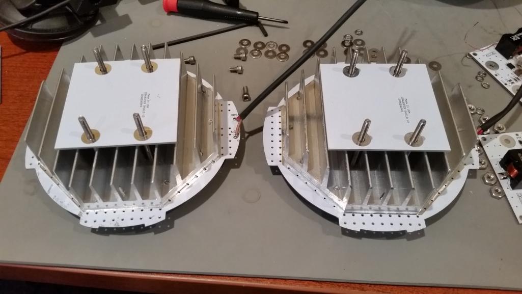 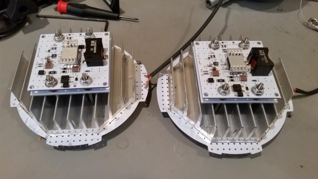 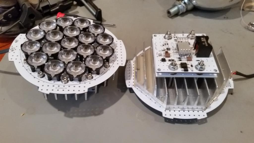 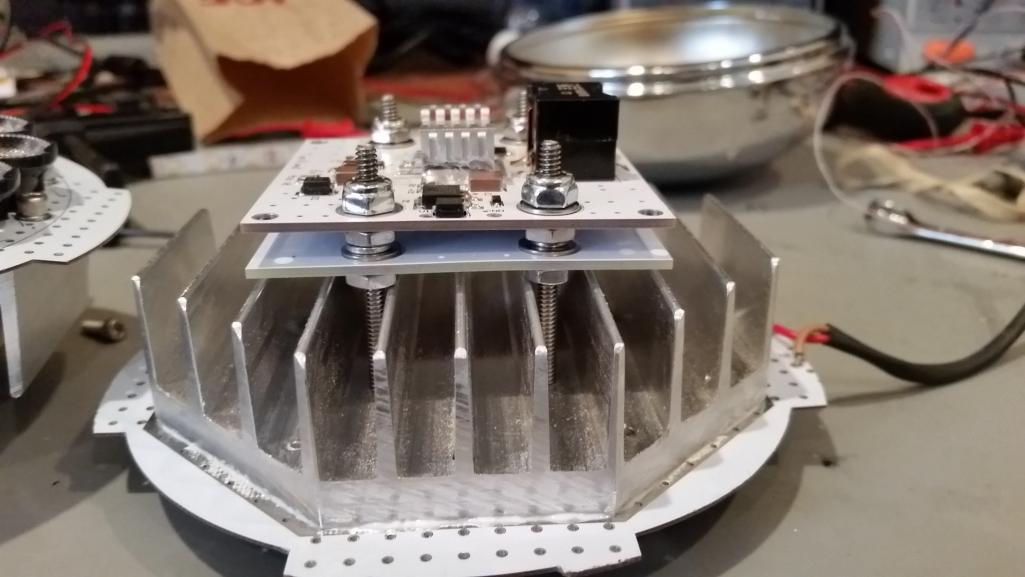
|
|
|
|
| Mueller |
May 2 2018, 10:54 AM
Post
#11
|
|
914 Freak! Group: Members Posts: 17,146 Joined: 4-January 03 From: Antioch, CA Member No.: 87 Region Association: None |
Pretty damn slick and you've inspired me to do more research and learning about LED's.
(looking forward to your LED setup for my car, hope they show up this week so I can install them (IMG:style_emoticons/default/smile.gif) ) Any concerns about the ambient temperature of the customers location? I'd hope he only ran them at night when it is usually cooler, however if he lives in a hot humid location? |
|
|
|
|
1 User(s) are reading this topic (1 Guests and 0 Anonymous Users)
0 Members:

|
Lo-Fi Version | Time is now: 28th April 2024 - 12:10 PM |
Invision Power Board
v9.1.4 © 2024 IPS, Inc.