|
|
|
Porsche, and the Porsche crest are registered trademarks of Dr. Ing. h.c. F. Porsche AG.
This site is not affiliated with Porsche in any way. Its only purpose is to provide an online forum for car enthusiasts. All other trademarks are property of their respective owners. |
|
|

  |

| spike |
 Aug 24 2018, 08:38 AM Aug 24 2018, 08:38 AM
Post
#1
|
|
Newbie  Group: Members Posts: 3 Joined: 24-August 18 From: Scotland Member No.: 22,424 Region Association: None |
Hi all. This is my first post on here. I have been given the interesting task of finishing a conversion that was started some 20years ago! On top of that the car has an 80's or 90's temperamental immobiliser fitted according to the owner. I am going to remove the immobiliser completely. The problems are the electrics.
Here are some of the problems I currently have:- When marrying up the 14 pin connector of the engine loom to the relay board as per a diagram I was supplied with the car it doesn't make any sense. I removed the D+, D- and DF wires, fitted new terminals and connected them to the appropriate 3 pins on the relay board. I then moved the red wires pin (from the alternator) from pin 14 to pin 7. Pin 14 on the relay board doesn't exist and since putting it into pin 7 both the ignition light and the oil pressure light come on permanently on the dash, even when the ignition is off. Someone has cut the black/purple wire at the distributor so it no longer goes to the dizzy and turned it into an earth to the engine block. The relay board was also mounted 180degrees out so the engine loom 14 pin connector was plugged into the cars 14 pin connector block and vice versa, so I don't know if any damage has occurred to any components by a previous mechanic turning on the ignition. The BHKZ unit has no power supply as the red wire for it just hangs out of the loom. I can't find or don't know if I need the following components either that are in the diagram I have :- speed switch/relay. Thermostat time switch. Auxiliary starting relay and Control valve. I have found plenty of info online about how to do the conversion and the parts required, but am struggling to find any information on the wiring side of the conversion. Any help/advice is massively appreciated. Thanks |
   |

 
|
| larryM |
Aug 24 2018, 12:03 PM
Post
#2
|
|
emoze Group: Members Posts: 891 Joined: 1-January 03 From: mid- California Member No.: 65 Region Association: Northern California |
aftermarket alarm setups are a PITA - you are right to get rid of it not really much wire difference twixt prior -4 & -6 assuming your 2.4 is carb'd & has a oem distributor - you just want to undo the dpo mess & put it back to oem wiring? - could be mis-connected both under the dash & at the engine compartment and/OR the dpo could have moved wires in the connectors from one position to another just take your manual's wiring diagram and trace end-to-end on those wires & thru the connectors with an ohmeter to figure out what the dpo did then undo it & put it back to the way your manual's 914 wiring diagram shows if you don't have a real 914 wiring diagram or manual, get one quick - if all you have is a smallish Haynes diagram - take it to the copy-shop & enlarge it to table-top size |
|
|
|
| IronHillRestorations |
Aug 24 2018, 12:13 PM
Post
#3
|
|
I. I. R. C. Group: Members Posts: 6,819 Joined: 18-March 03 From: West TN Member No.: 439 Region Association: None |
A little more info would be helpful.
What year car? What engine? What induction? Internal or externally regulated alternator? |
|
|
|
| spike |
Aug 25 2018, 02:44 AM
Post
#4
|
|
Newbie Group: Members Posts: 3 Joined: 24-August 18 From: Scotland Member No.: 22,424 Region Association: None |
QUOTE(Perry Kiehl @ Aug 24 2018, 07:13 PM)  A little more info would be helpful. What year car? What engine? What induction? Internal or externally regulated alternator? Sorry, here is more info. Car is a 72 914 Engine is a 72 or 73 2.4L with Bosch MFi Induction looks like a standard set up, if thats what you're asking. How do I know if the alternator is internally or externally regulated? The ignition looks standard with a Bosch distributor which has points and a 6,500rpm rotor arm fitted. The engine cover is painted yellow, but dont know if that has any significance at all. |
|
|
|
| jtf914 |
Aug 25 2018, 04:29 AM
Post
#5
|
|
Member Group: Members Posts: 428 Joined: 31-December 02 From: Burlington, CT Member No.: 58 Region Association: North East States |
QUOTE(spike @ Aug 25 2018, 04:44 AM) The engine cover is painted yellow, but dont know if that has any significance at all. Sorry, I’m no help on the wiring. I agree with LarryM, remove the immobilizer and try and return as much of the wiring to oem as you can, then move forward. Wiring diagrams will make you go blind, but they will be your best friend. Quick google search brought up this thread from PP: http://forums.pelicanparts.com/porsche-914...ion-wiring.html The yellow shroud indicates the motor is a 2.4T with mfi. A 1972 2.4E shroud would be green and a 2.4S shroud would be red. (IMG:style_emoticons/default/welcome.png) |
|
|
|
| spike |
Aug 26 2018, 02:29 PM
Post
#6
|
|
Newbie Group: Members Posts: 3 Joined: 24-August 18 From: Scotland Member No.: 22,424 Region Association: None |
QUOTE(jtf914 @ Aug 25 2018, 11:29 AM) QUOTE(spike @ Aug 25 2018, 04:44 AM) The engine cover is painted yellow, but dont know if that has any significance at all. Sorry, I’m no help on the wiring. I agree with LarryM, remove the immobilizer and try and return as much of the wiring to oem as you can, then move forward. Wiring diagrams will make you go blind, but they will be your best friend. Quick google search brought up this thread from PP: http://forums.pelicanparts.com/porsche-914...ion-wiring.html The yellow shroud indicates the motor is a 2.4T with mfi. A 1972 2.4E shroud would be green and a 2.4S shroud would be red. Thanks for the help. Agreed, that I need to restore the original wiring first and remove the immobiliser. The link looks exactly like the problem I have with 5 wires coming out the back of the shroud. I'll get back into it tomorrow with a fresh head as my brain went into meltdown with so many issues to be sorted. Fingers crossed. |
|
|
|
| larryM |
Aug 26 2018, 10:19 PM
Post
#7
|
|
emoze Group: Members Posts: 891 Joined: 1-January 03 From: mid- California Member No.: 65 Region Association: Northern California |
after you sort out the correct oem 914 wiring all the way from dash to the relay plate plug,
then look at a 911 diagram to see if the pinouts & colors are same or different (likely) twixt your 914 & the 911 harness - (MFI 911 did not have that 914-type relay plate) - then trace each wire end-to-end to the correct 911 item you have to figure out if the dpo ever updated that 2.4 alternator to an IR - given you say it's been dead for 15+ yrs, chances are it's an externally regulated type on my old 911, the alternator control ("D") wires just went to a small 3-prong that plugged into the regulator, whilst the 12v battery wire hooked up at the starter solenoid to the main 12v cable fwiw i'd just bypass that relay plate & direct wire the ign & charging this may help 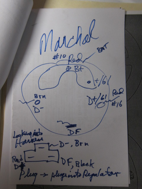 |
|
|
|
| porschetub |
Aug 27 2018, 01:25 AM
Post
#8
|
|
Advanced Member Group: Members Posts: 4,870 Joined: 25-July 15 From: New Zealand Member No.: 18,995 Region Association: None |
QUOTE(spike @ Aug 25 2018, 08:44 PM) QUOTE(Perry Kiehl @ Aug 24 2018, 07:13 PM) A little more info would be helpful. What year car? What engine? What induction? Internal or externally regulated alternator? Sorry, here is more info. Car is a 72 914 Engine is a 72 or 73 2.4L with Bosch MFi Induction looks like a standard set up, if thats what you're asking. How do I know if the alternator is internally or externally regulated? The ignition looks standard with a Bosch distributor which has points and a 6,500rpm rotor arm fitted. The engine cover is painted yellow, but dont know if that has any significance at all. I think you should have an external regulator unless some has changed the altenator, sounds like you have an MFI motor ,they run nice but everthing in the system needs to be up to spec and expensive to sort if not ,the mechanical fuel pump comes to mind straight off. |
 |
|
|
1 User(s) are reading this topic (1 Guests and 0 Anonymous Users)
0 Members:

|
Lo-Fi Version | Time is now: 2nd July 2025 - 01:47 PM |
Invision Power Board
v9.1.4 © 2025 IPS, Inc.