|
|
|
Porsche, and the Porsche crest are registered trademarks of Dr. Ing. h.c. F. Porsche AG.
This site is not affiliated with Porsche in any way. Its only purpose is to provide an online forum for car enthusiasts. All other trademarks are property of their respective owners. |
|
|

  |

| Spoke |
 Jun 11 2019, 07:51 PM Jun 11 2019, 07:51 PM
Post
#101
|
|
Jerry  Group: Members Posts: 7,400 Joined: 29-October 04 From: Allentown, PA Member No.: 3,031 Region Association: None |
Here's the 911 board with the reflector installed. The fit is very good and should be an easy update for anyone. One annoyance with the converter module is it has no undervoltage lockout. It starts turning on at about 3-4V and can run very hot at this voltage.
The 911 foglight burns about 9W. Attached thumbnail(s) 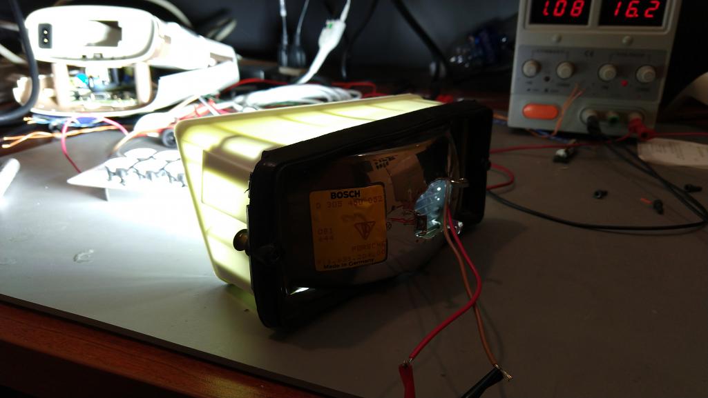
|
   |

 
|
| DRPHIL914 |
Jul 16 2019, 07:49 AM
Post
#102
|
|
Dr. Phil Group: Members Posts: 5,950 Joined: 9-December 09 From: Kennesaw, GA Member No.: 11,106 Region Association: South East States |
QUOTE(Spoke @ Jun 11 2019, 09:44 PM)  Finally got the 2nd 914 foglight assembled. This discrete converter kicks ass but is a pain in the ass to assemble. The board on the left is a 911 foglight. I'm hoping to get those installed on my 930 this weekend. The 911 foglight uses a boost module and is much easier to assemble. The only difference at this point is the module is 350ma whereas the discrete converter is 500ma. I'm hoping the 911 foglight will still be significantly brighter than the OEM bulb even with the lower 350ma current. If the 911 foglight is bright enough, I may go with the module for the 914 foglights. I have 4 of these first 914 boards that I will build up. I'll put a pair on my 914 and give the other pair to mepstein. any updates on the beta testing of these? hoping to get a set when you are ready to do so. @spoke @mepstein Dr. Phil |
|
|
|
| Spoke |
Jul 17 2019, 06:20 AM
Post
#103
|
|
Jerry Group: Members Posts: 7,400 Joined: 29-October 04 From: Allentown, PA Member No.: 3,031 Region Association: None |
QUOTE(DRPHIL914 @ Jul 16 2019, 09:49 AM) QUOTE(Spoke @ Jun 11 2019, 09:44 PM) Finally got the 2nd 914 foglight assembled. This discrete converter kicks ass but is a pain in the ass to assemble. The board on the left is a 911 foglight. I'm hoping to get those installed on my 930 this weekend. The 911 foglight uses a boost module and is much easier to assemble. The only difference at this point is the module is 350ma whereas the discrete converter is 500ma. I'm hoping the 911 foglight will still be significantly brighter than the OEM bulb even with the lower 350ma current. If the 911 foglight is bright enough, I may go with the module for the 914 foglights. I have 4 of these first 914 boards that I will build up. I'll put a pair on my 914 and give the other pair to mepstein. any updates on the beta testing of these? hoping to get a set when you are ready to do so. @spoke @mepstein Dr. Phil I did get a 2nd set of fogs assembled for mepstein but haven't refurbished his or my foglight cases. Don't want to put the foglights in beat up cases. It will be a few weeks before I get our foglights ready to test out. I'm further ahead with the 911 foglights as they use a dc-dc converter module with very few discrete components and are very easy to assemble. Any further 914 fogs will use this module. Here's a link at Pelican: 911 Foglights This is the 2nd set of 911 fogs built and sent to a 911 guy for him to install and evaluate. 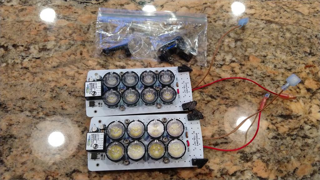 |
|
|
|
| DRPHIL914 |
Jul 17 2019, 06:28 AM
Post
#104
|
|
Dr. Phil Group: Members Posts: 5,950 Joined: 9-December 09 From: Kennesaw, GA Member No.: 11,106 Region Association: South East States |
QUOTE(Spoke @ Jul 17 2019, 08:20 AM) QUOTE(DRPHIL914 @ Jul 16 2019, 09:49 AM) QUOTE(Spoke @ Jun 11 2019, 09:44 PM) Finally got the 2nd 914 foglight assembled. This discrete converter kicks ass but is a pain in the ass to assemble. The board on the left is a 911 foglight. I'm hoping to get those installed on my 930 this weekend. The 911 foglight uses a boost module and is much easier to assemble. The only difference at this point is the module is 350ma whereas the discrete converter is 500ma. I'm hoping the 911 foglight will still be significantly brighter than the OEM bulb even with the lower 350ma current. If the 911 foglight is bright enough, I may go with the module for the 914 foglights. I have 4 of these first 914 boards that I will build up. I'll put a pair on my 914 and give the other pair to mepstein. any updates on the beta testing of these? hoping to get a set when you are ready to do so. @spoke @mepstein Dr. Phil I did get a 2nd set of fogs assembled for mepstein but haven't refurbished his or my foglight cases. Don't want to put the foglights in beat up cases. It will be a few weeks before I get our foglights ready to test out. I'm further ahead with the 911 foglights as they use a dc-dc converter module with very few discrete components and are very easy to assemble. Any further 914 fogs will use this module. Here's a link at Pelican: 911 Foglights This is the 2nd set of 911 fogs built and sent to a 911 guy for him to install and evaluate. thanks for the update . If I had known your issues were mainly dealing with the condition of the fog lights I could have sent you mine, they are mint condition no rust or corrosion. in fact if you make that next set with this 911converter you are now planning on using I will pull these off the car and send them to you if you want to put them in and do some testing or have me test them. I have some other running lights I can put in or just go with out them for a while , I rarely drive the car in this 100 degree heat. I would like to have it complete before Okteenerfest though. either way let me know. Phil |
|
|
|
| mepstein |
Jul 17 2019, 06:53 AM
Post
#105
|
|
914-6 GT in waiting Group: Members Posts: 20,803 Joined: 19-September 09 From: Landenberg, PA/Wilmington, DE Member No.: 10,825 Region Association: MidAtlantic Region |
Jerry, I wish I sent you better condition fogs. I just know it was taking me so long to send anything that I wanted you to have something to work with. I found the nicer sets when I stopped looking for them. I can refurbish the housings at work, powdercoat, ect so don't feel like you have to do more work on these. I promise not to post pictures until they look pretty. (IMG:style_emoticons/default/biggrin.gif)
|
|
|
|
| ConeDodger |
Jul 17 2019, 12:34 PM
Post
#106
|
|
Apex killer! Group: Members Posts: 24,494 Joined: 31-December 04 From: Tahoe Area Member No.: 3,380 Region Association: Northern California |
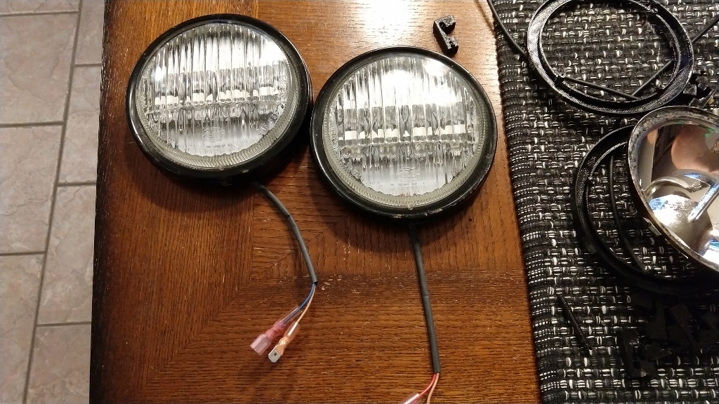
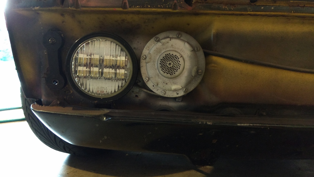
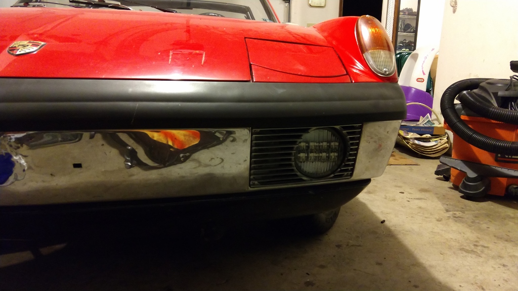
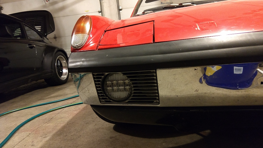
I’d love to do these but my fogs are actually aftermarket. Pilots I think...
Attached image(s) 
|
|
|
|
| ConeDodger |
Jul 17 2019, 12:43 PM
Post
#107
|
|
Apex killer! Group: Members Posts: 24,494 Joined: 31-December 04 From: Tahoe Area Member No.: 3,380 Region Association: Northern California |
@Spoke any chance of doing amber?
|
|
|
|
| Spoke |
Jul 18 2019, 10:51 AM
Post
#108
|
|
Jerry Group: Members Posts: 7,400 Joined: 29-October 04 From: Allentown, PA Member No.: 3,031 Region Association: None |
QUOTE(ConeDodger @ Jul 17 2019, 02:43 PM) Interesting thought. I'm not sure amber would work with the board designed for white LEDs. The reason is the voltage drop of the amber LED is 2V and the voltage drop of the white is 3V. With 8 LEDs in series, the amber LEDs would drop 16V whereas the white will drop 24V. The issue is the boost converter I've targeted requires at least 3V difference between input (up to 14V) and output (16V for 8 amber; 24V for 8 white). If 2 more amber LEDs were added, then the voltage drop would be 20V and compatible with the converter. I could either make a separate 10-LED board for ambers or make one board which would accept 8 or 10 LEDs. |
|
|
|
| Spoke |
Jul 29 2019, 08:54 PM
Post
#109
|
|
Jerry Group: Members Posts: 7,400 Joined: 29-October 04 From: Allentown, PA Member No.: 3,031 Region Association: None |
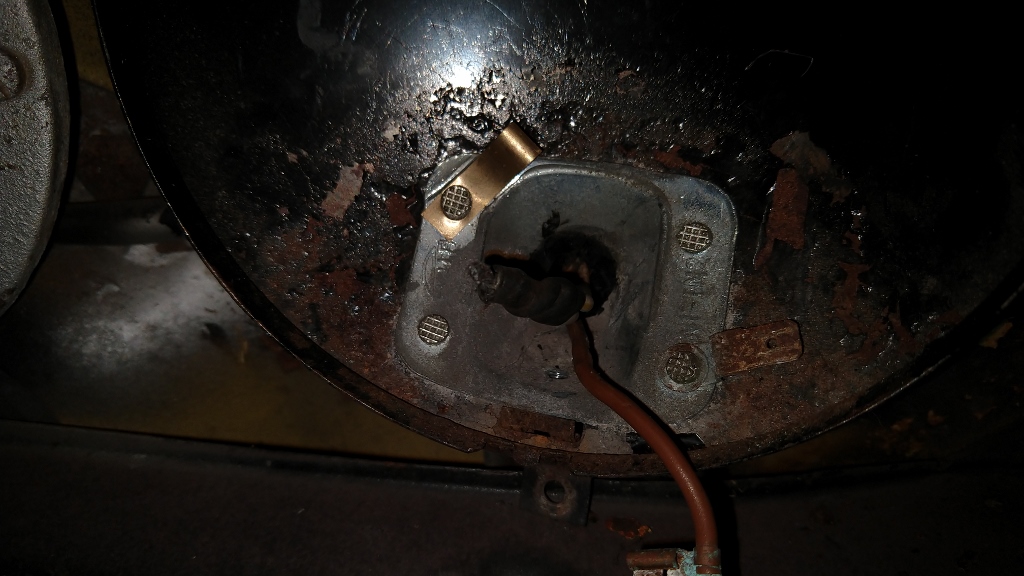
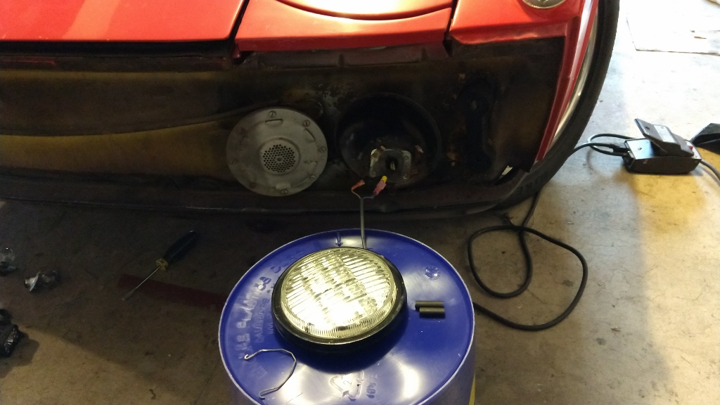
Finally got around to installing the LED foglights on my 914. The following posts detail the installation of these LEDs into an early 914 foglight.
The later foglight lenses have less room inside the lens and require a thick spacer (3-5mm) so the LEDs fit under the glass lens. On the early foglights, this spacing isn't an issue. Start by removing the bumper. 2 bolts on each side. I loosened the bolts all round then removed them on one side and rested the bumper on a bucket while the bolts were removed on the other side. 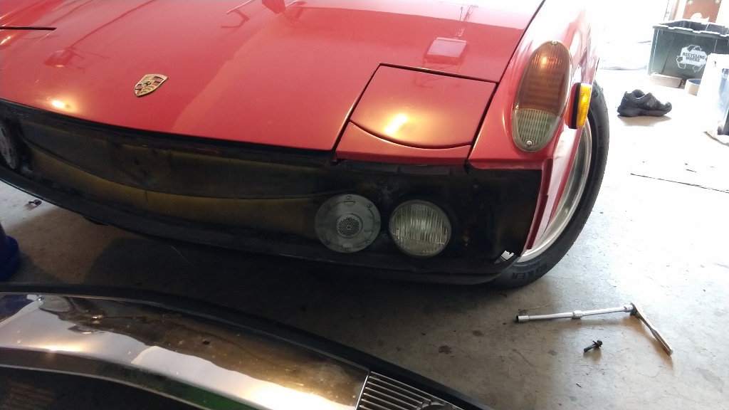 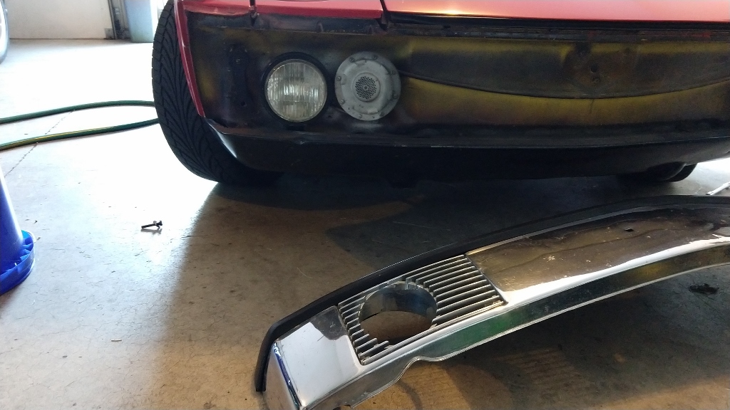 Open up the foglight fixture by removing the small screw on the bottom of the fixture which holds the bezel in place. 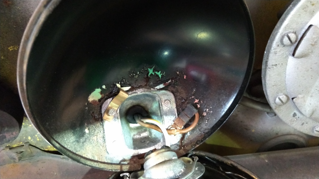 Disconnect the bulb holder from the bezel/lens/reflector assembly. Take the assembly to the workbench. Do both sides. On the car, the bulb holder is removed from the 12V wire by loosening the flat-head screw holding the 12V wire to the bulb fixture. The bulb and its holder will not be used. 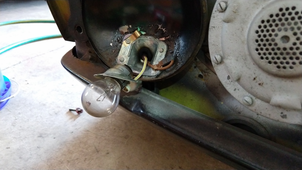 |
|
|
|
| Spoke |
Jul 29 2019, 09:12 PM
Post
#110
|
|
Jerry Group: Members Posts: 7,400 Joined: 29-October 04 From: Allentown, PA Member No.: 3,031 Region Association: None |
The bezel/lens/reflector assembly is separated by removing the 4 metal clips behind the bezel. Always wear eye protection when removing/replacing these clips because they have a tendency to fly across the room.
Also remove/replace in a smallish, clean or clutter-free room. Reason for this is when these clips fly, they can go all over the place and are hard to find. Chances are at least one of these spring clips will fly during removal/replacement. Remove the clips with a flathead screwdriver depressing the longer of the 2 arms of the clip. Notice that the clips are different on the left assembly than the right assembly. Take a picture of the assembly before removing the clips so the orientation of the clips is remembered. 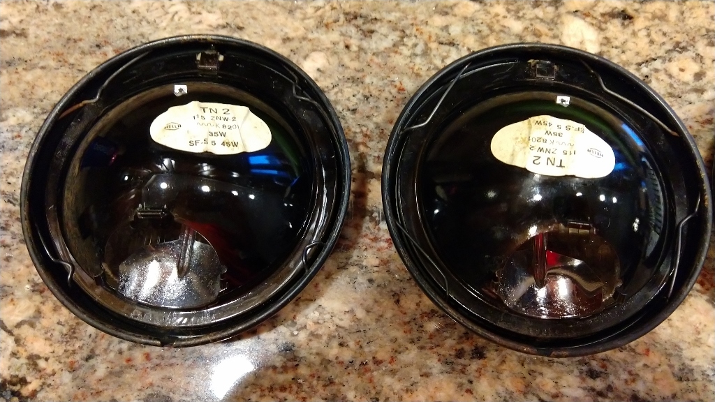 Once disassembled, clean the glass lens and refurbish the bezel as you desire. I only washed the bezels on my car. Replace the rubber gasket around the lens with a new one. These are available at 914rubber. Notice the tape on the top part of the LED lenses. This is to attempt to cut off the light bleed upward. It does cut off some light on the upper side but isn't 100%. 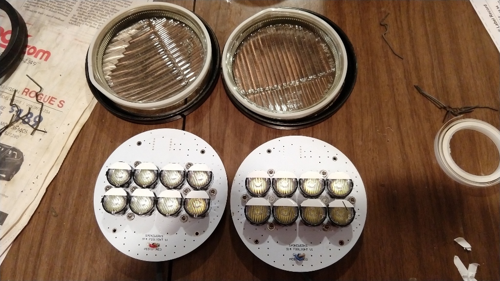 This is the spacer ring to align the LED board to the glass bezel. It will be attached to the board when the board is assembled. 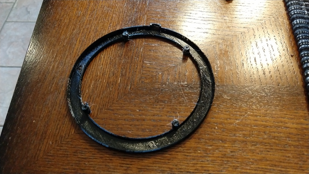 |
|
|
|
| Spoke |
Jul 29 2019, 09:17 PM
Post
#111
|
|
Jerry Group: Members Posts: 7,400 Joined: 29-October 04 From: Allentown, PA Member No.: 3,031 Region Association: None |
Here's the board with the alignment ring attached.
 When mating the LED board with the lens, make sure the gasket remains in place. 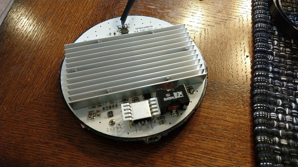 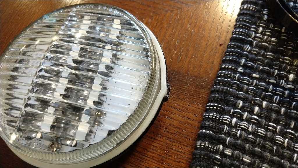 |
|
|
|
| Spoke |
Jul 29 2019, 09:22 PM
Post
#112
|
|
Jerry Group: Members Posts: 7,400 Joined: 29-October 04 From: Allentown, PA Member No.: 3,031 Region Association: None |
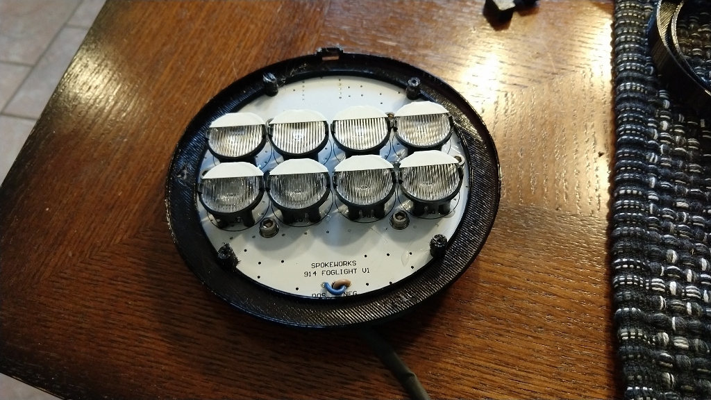
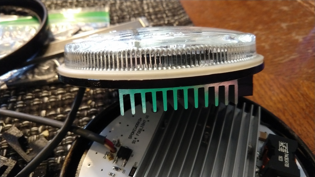
Here is the board mated to the lens. The alignment tab tat the top of the lens fits into the alignment gap at the top of the board alignment ring.
   |
|
|
|
| Spoke |
Jul 29 2019, 09:28 PM
Post
#113
|
|
Jerry Group: Members Posts: 7,400 Joined: 29-October 04 From: Allentown, PA Member No.: 3,031 Region Association: None |
Now comes the tricky part: getting the spring clips back on to hold the bezel/lens/board assembly together. The lens is self-aligned with the bezel via a ridge on the outside bottom of the lens. There is a recess in the bezel where this ridge will fit.
To assist this step, 4 special clips are provided to hold the board in place. These clip right on and hold the board in place so the spring clips can be installed. 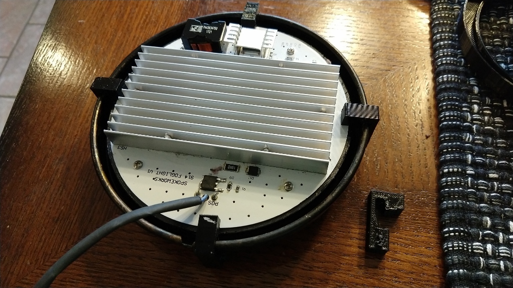 Reinstall the spring clips, one on each side of the heat sink. An installation tool will be provide to help install the spring clips. Again use eye protection and do the work in a smallish, clutter-free room in case one of the clips takes off. 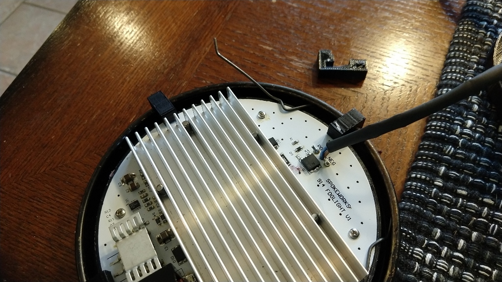 |
|
|
|
| Spoke |
Jul 29 2019, 09:32 PM
Post
#114
|
|
Jerry Group: Members Posts: 7,400 Joined: 29-October 04 From: Allentown, PA Member No.: 3,031 Region Association: None |
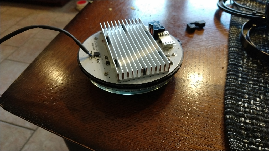
Reinstall the spring clips to both lights and we're almost ready for installation. Need to add quick connect spades to the 12V wires and clean the ground spade.
  |
|
|
|
| Spoke |
Jul 29 2019, 09:40 PM
Post
#115
|
|
Jerry Group: Members Posts: 7,400 Joined: 29-October 04 From: Allentown, PA Member No.: 3,031 Region Association: None |
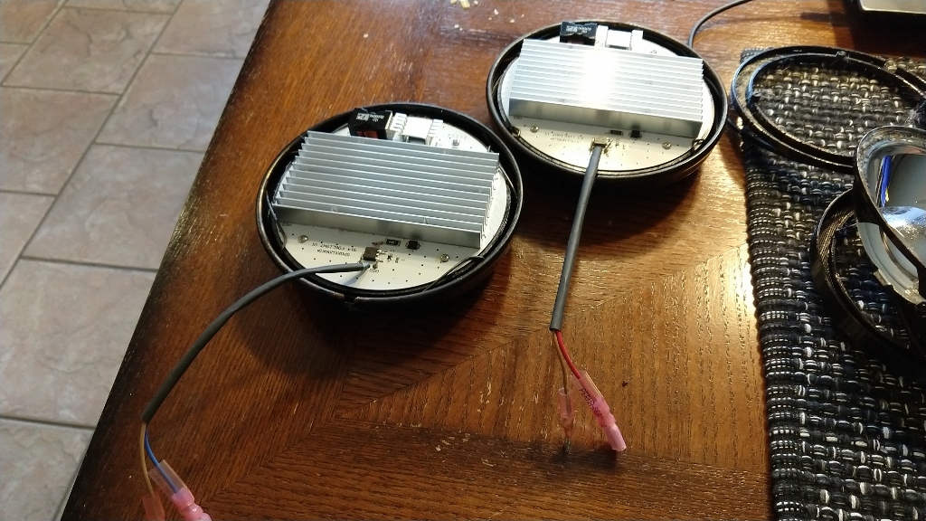
The driver side 12V wire is kind of a pain since it is 2 wires soldered together with some shrink wrap on it. The 2 wires were also flattened by the attachment of the wires to the bulb holder. I had to use a spade made for 10-12 gauge wire.
 This spade isn't optimal as it should be shielded but it was all my FLAPS had in the 10-12 gauge range. The ground spade needs to be removed from the fixture and cleaned. 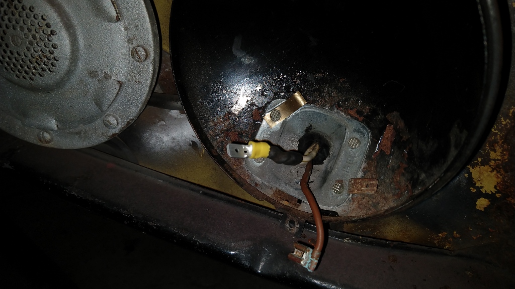 The passenger side was easier since it had only one wire with soldered end. I was able to use a shielded male spade on this one. The spades will be included with the LED boards for easy installation. 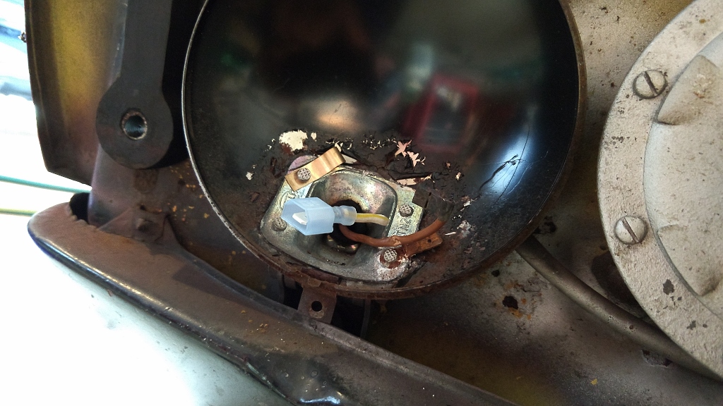 |
|
|
|
| Spoke |
Jul 29 2019, 09:45 PM
Post
#116
|
|
Jerry Group: Members Posts: 7,400 Joined: 29-October 04 From: Allentown, PA Member No.: 3,031 Region Association: None |
Time to connect the LEDs and test them. The board is set on a bucket or other item so wires can be attached without stressing any connections. Do not let the board hang by its wires. Also avoid touching any of the electronics on the board.
Before making the connect to the ground spade, a short section of heat shrink tubing is added to insulate the ground spade. Once the ground connection is made, slide the tubing into place and heat it. 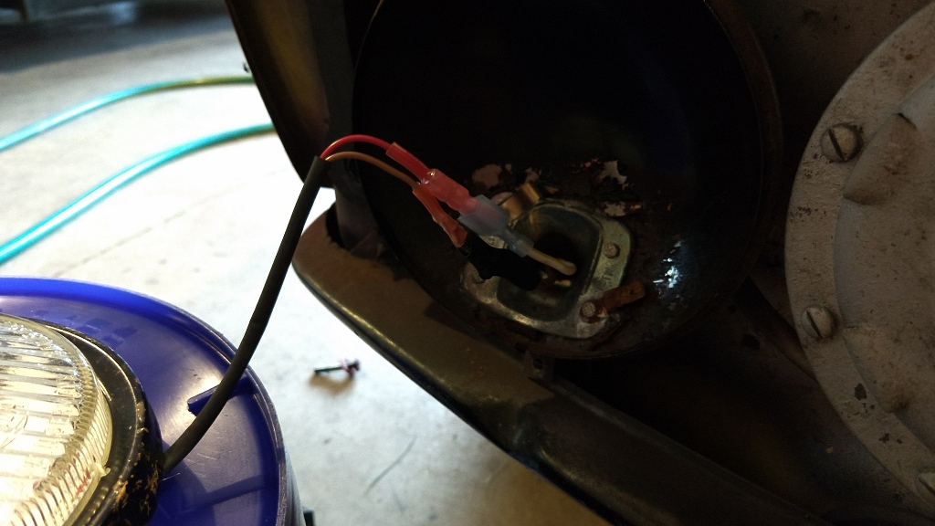 Test the board before continuing. If any connections are not made, now is the time to adjust things. 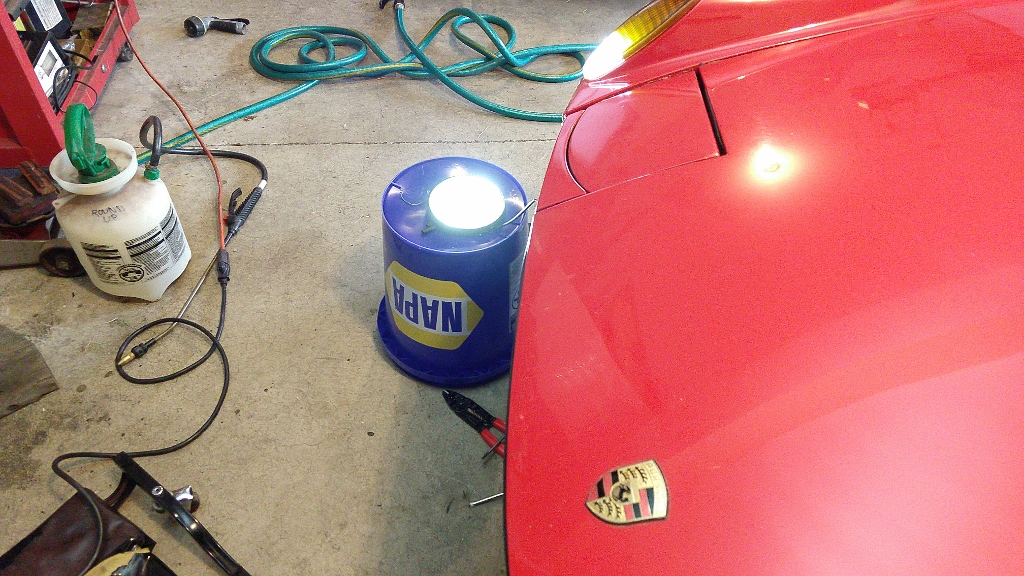 |
|
|
|
| Spoke |
Jul 29 2019, 09:48 PM
Post
#117
|
|
Jerry Group: Members Posts: 7,400 Joined: 29-October 04 From: Allentown, PA Member No.: 3,031 Region Association: None |
Install the bezel assembly making sure the wires are all inside the unit. Make sure the bezel is on straight. Replace the locking clip on the bottom and replace the small screw to hold the locking clip in place. Test the light again.
 |
|
|
|
| Spoke |
Jul 29 2019, 09:53 PM
Post
#118
|
|
Jerry Group: Members Posts: 7,400 Joined: 29-October 04 From: Allentown, PA Member No.: 3,031 Region Association: None |
Repeat the installation on the other side. Support the assembly, slide the heat shrink on the ground wire, attach wires and heat the ground tubing. Test the light.
 The wire should tuck nicely inside the fixture. Make sure the wire stays inside the fixture during installation. 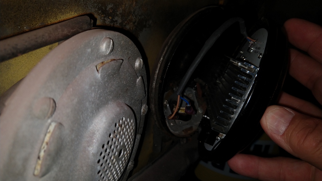 Install the bezel making sure the bezel assembly is straight. Screw in the locking clip and retest. 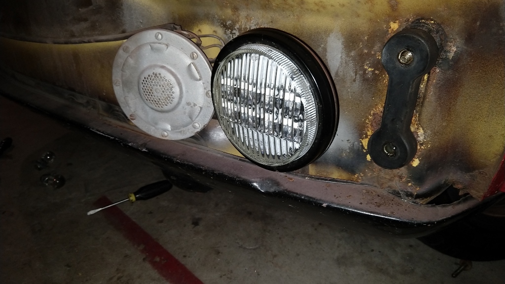 |
|
|
|
| Spoke |
Jul 29 2019, 09:54 PM
Post
#119
|
|
Jerry Group: Members Posts: 7,400 Joined: 29-October 04 From: Allentown, PA Member No.: 3,031 Region Association: None |
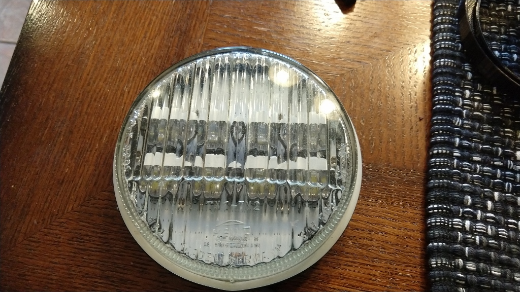
Replace the bumper and the installation is finished.
  |
|
|
|
| advman89 |
Jul 30 2019, 11:37 AM
Post
#120
|
|
Member Group: Members Posts: 120 Joined: 8-July 19 From: Chicago, IL Member No.: 23,286 Region Association: Upper MidWest |
...and after all that.....964 Fog Lamps. You can't do anything but stock bulbs in them.
|
|
|
|
|
2 User(s) are reading this topic (2 Guests and 0 Anonymous Users)
0 Members:

|
Lo-Fi Version | Time is now: 8th July 2026 - 09:31 AM |
Invision Power Board
v9.1.4 © 2026 IPS, Inc.