|
|
|
Porsche, and the Porsche crest are registered trademarks of Dr. Ing. h.c. F. Porsche AG.
This site is not affiliated with Porsche in any way. Its only purpose is to provide an online forum for car enthusiasts. All other trademarks are property of their respective owners. |
|
|

  |

| Spoke |
 Apr 13 2019, 08:45 AM Apr 13 2019, 08:45 AM
Post
#1
|
|
Jerry  Group: Members Posts: 7,400 Joined: 29-October 04 From: Allentown, PA Member No.: 3,031 Region Association: None |
The design of an early foglight LED board has begun. mepstein sent me a couple of foglight fixtures to use to design the board. 2 main issues are fitment and heat dissipation. If things work out ok the design should be able to be re-laid out for the later square foglight.
The board will have 8 Cree XP-G3 high power surface mount LEDs with 350ma current each. These will burn about 1W of power with a total power dissipation expected to be less than 10W. Hopefully these will be almost as bright as a headlight. Each LED will have its own focusing lens. The lenses are Carclo 10192 elliptical 20mm lenses. The light pattern for the 10192 lens is shown below.  This is the spectral dispersion for the lens.  |
   |

 
|
| Spoke |
Apr 13 2019, 08:51 AM
Post
#2
|
|
Jerry Group: Members Posts: 7,400 Joined: 29-October 04 From: Allentown, PA Member No.: 3,031 Region Association: None |
The LEDs will be connected in series and driven by a Linear Technologies LT3755 switching converter. It will be the same circuit as applied to the Porsche 356 running lights previously designed.
That running light had 19 LEDs running 275ma each. This one burned about 16W total. The switching converter was placed on a separate PCB as a large heatsink was mounted behind the LEDs. The 914 foglight fixture is much smaller so only 8 LEDs will be mounted with the switching converter mounted on the backside of a single PCB. Attached thumbnail(s) 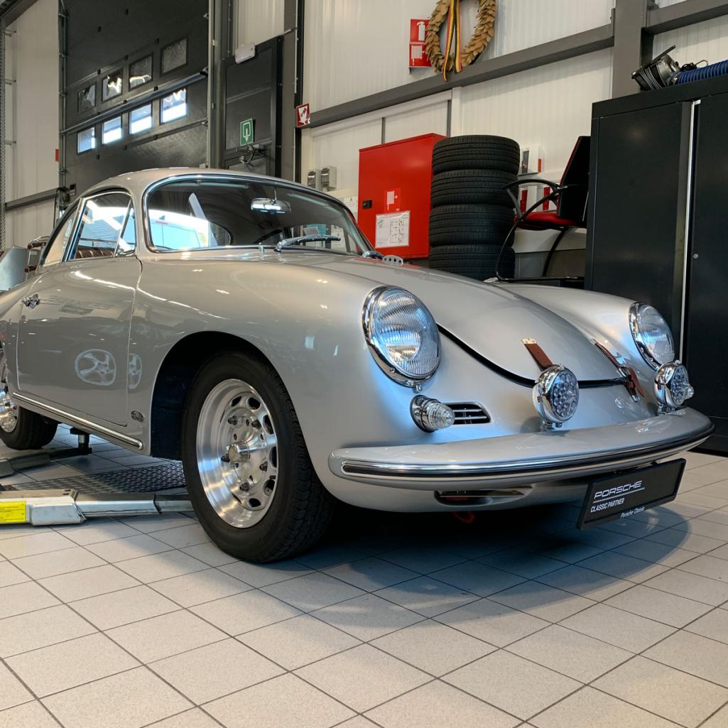 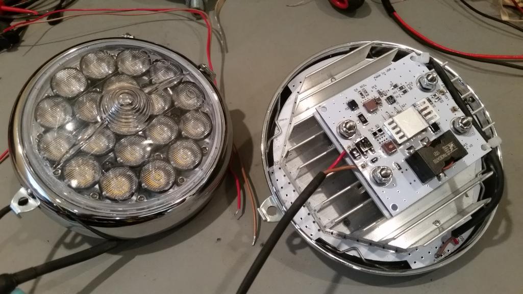
|
|
|
|
| Spoke |
Apr 13 2019, 08:58 AM
Post
#3
|
|
Jerry Group: Members Posts: 7,400 Joined: 29-October 04 From: Allentown, PA Member No.: 3,031 Region Association: None |
This is what the board looks like right now. It may likely change as the layout proceeds. The heatsink is 2 x 4 inches and will back the LEDs. The rest of the space will be used on the back will be used by the switching converter.
The switching converter could be mounted on the front side but I'm not sure if it would look ok since you'd be able to see the hardware. It would make the assembly much easier to have everything on one side. Attached image(s) 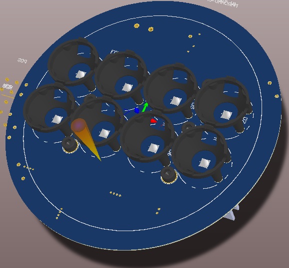 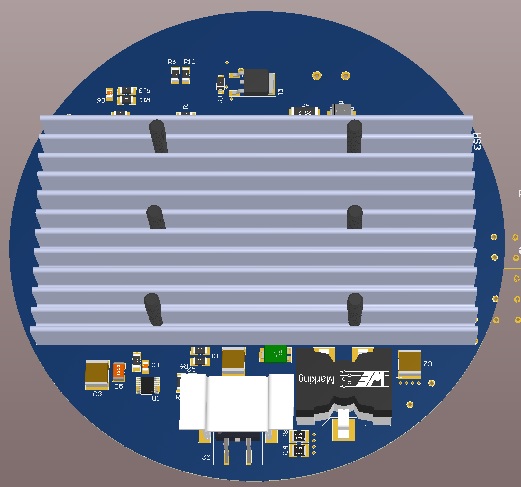
|
|
|
|
| mepstein |
Apr 13 2019, 12:16 PM
Post
#4
|
|
914-6 GT in waiting Group: Members Posts: 20,802 Joined: 19-September 09 From: Landenberg, PA/Wilmington, DE Member No.: 10,825 Region Association: MidAtlantic Region |
I don't understand any of this but it sure looks great. Can't wait to go full LED. Maybe the hood lights next?
I think the Cibie's are used on many other marque's. Attached thumbnail(s) 
|
|
|
|
| StratPlayer |
Apr 13 2019, 01:34 PM
Post
#5
|
|
StratPlayer Group: Members Posts: 3,374 Joined: 27-December 02 From: SLC, Utah Member No.: 27 Region Association: Rocky Mountains |
Will you be making these for the rectangle style fog lights?
|
|
|
|
| Luke M |
Apr 13 2019, 02:11 PM
Post
#6
|
|
Senior Member Group: Members Posts: 1,555 Joined: 8-February 05 From: WNY Member No.: 3,574 Region Association: North East States |
I'd be in for an early set once you get them done and tested.
|
|
|
|
| Spoke |
Apr 14 2019, 05:57 AM
Post
#7
|
|
Jerry Group: Members Posts: 7,400 Joined: 29-October 04 From: Allentown, PA Member No.: 3,031 Region Association: None |
QUOTE(StratPlayer @ Apr 13 2019, 03:34 PM)  Will you be making these for the rectangle style fog lights? Once the round board is proved out, yes I plan to migrate to the rectangle style. Also want to do a rectangle style for the 911. Attached thumbnail(s) 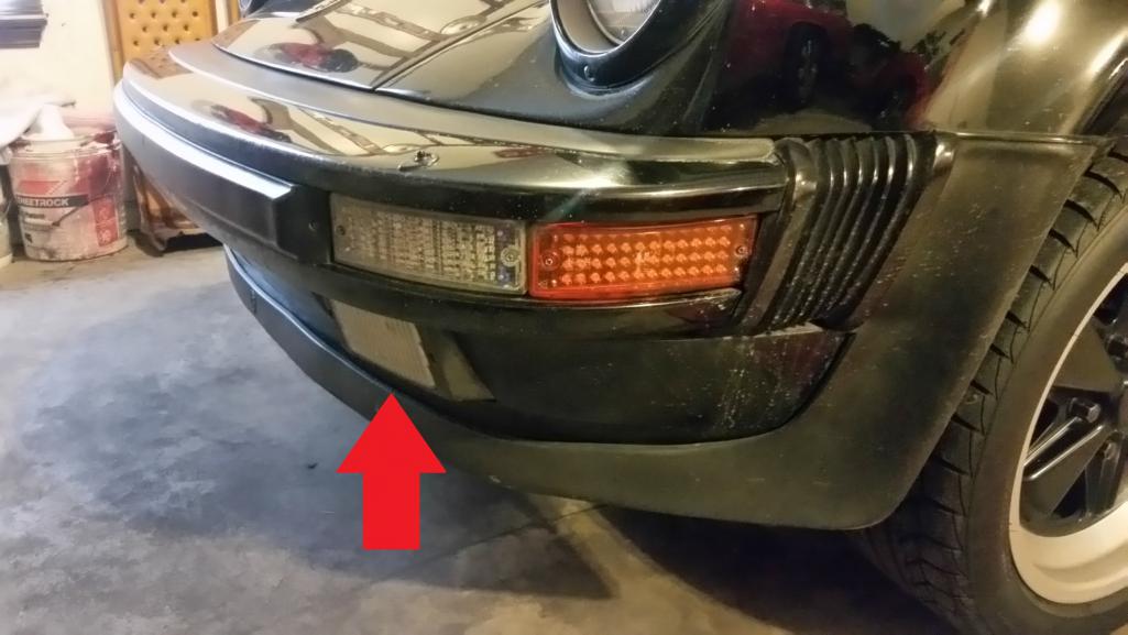
|
|
|
|
| 914-300Hemi |
Apr 14 2019, 06:05 AM
Post
#8
|
|
Senior Member Group: Members Posts: 1,391 Joined: 7-September 06 From: San Dimas, CA Member No.: 6,794 Region Association: Southern California |
Looks great Spoke.
|
|
|
|
| Spoke |
Apr 14 2019, 06:09 AM
Post
#9
|
|
Jerry Group: Members Posts: 7,400 Joined: 29-October 04 From: Allentown, PA Member No.: 3,031 Region Association: None |
This is the fixture I'll use to size the board. The reflector and original bulb socket will not be used.
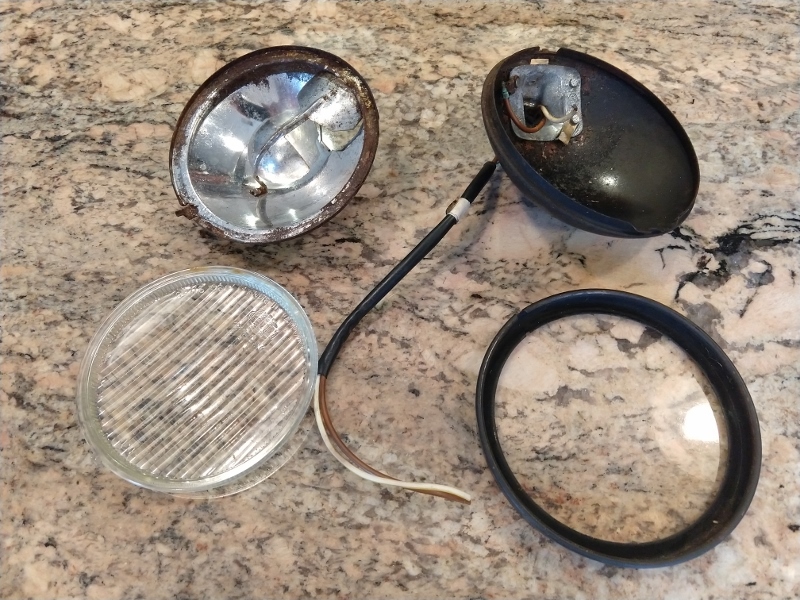 The wires from the original bulb are quite limited. The ground is a spade and the 12V is simply screwed onto the bulb socket. At least on my '71 these wires are quite short. It might be worthwhile to provide an entire pigtail for the LED board instead of trying to connect to the existing wires. 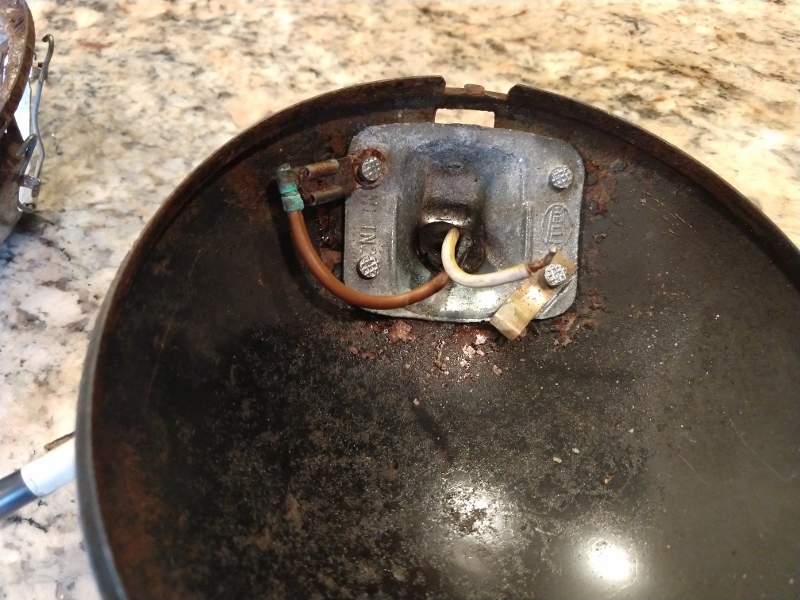 |
|
|
|
| Spoke |
Apr 14 2019, 06:15 AM
Post
#10
|
|
Jerry Group: Members Posts: 7,400 Joined: 29-October 04 From: Allentown, PA Member No.: 3,031 Region Association: None |
I printed the PCB front and bottom sides since I can't print both at the same time.
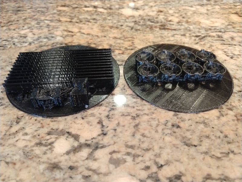 Here's the fitment of the PCB to the lens. This would be the clearance to the LED lenses. The depth of the lens leaves about 150mil gap between the PCB and the glass ledge. The PCB has to sit squarely on the ledge. 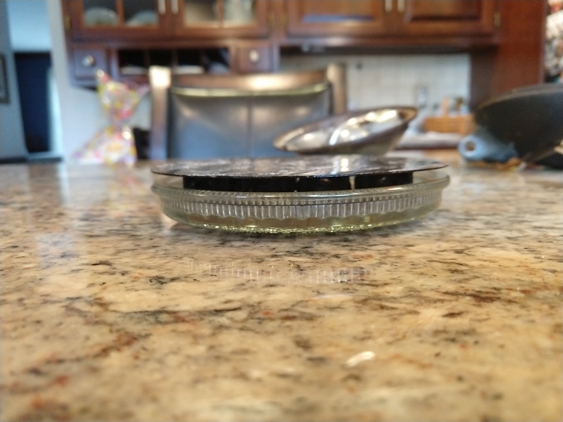 This spacer ring was printed to sit between the glass and the PCB to be able to mount the PCB. 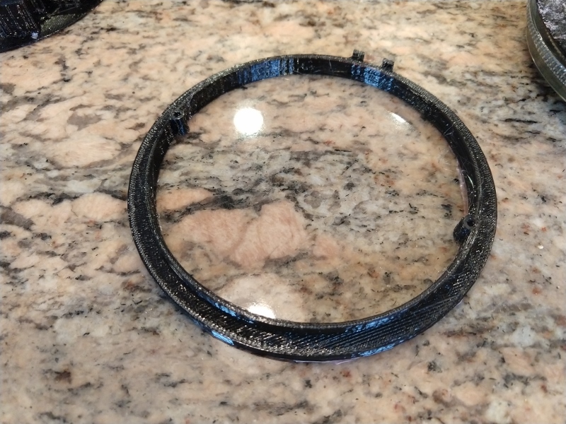 |
|
|
|
| Spoke |
Apr 14 2019, 06:21 AM
Post
#11
|
|
Jerry Group: Members Posts: 7,400 Joined: 29-October 04 From: Allentown, PA Member No.: 3,031 Region Association: None |
With the spacer attached, now the PCB can sit squarely on the glass.
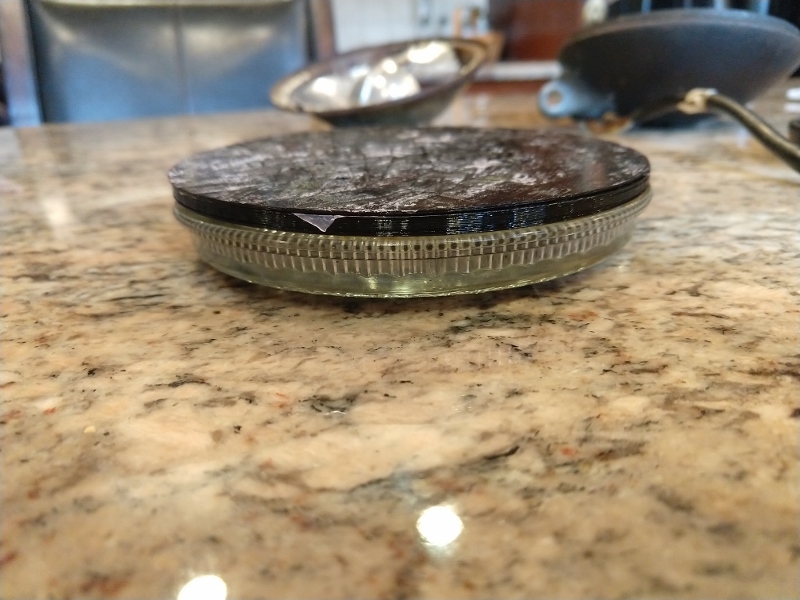 Because the spacer and PCB thickness, the original clips which hold the original reflector are too short to hold the PCB in place. The top clip is a new one made from spring wire. It will be able to hold the spacer and PCB in place. This will put the PCB on the trim ring and will make it easy to install the entire assembly. 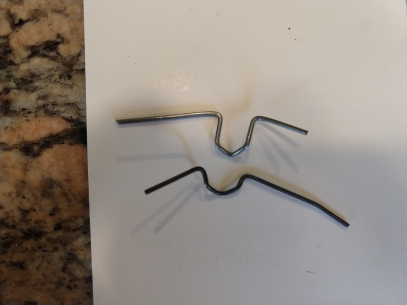 |
|
|
|
| Tbrown4x4 |
Apr 14 2019, 07:09 AM
Post
#12
|
|
Senior Member Group: Members Posts: 708 Joined: 13-May 14 From: Port Orchard, WA Member No.: 17,338 Region Association: None |
I'm totally supporting this. I drive at night 90% of the time, and my fog light reflectors are shot. I got a quote to re-silver at almost $100 each side. A quality LED conversion would give me my fog lights back.
|
|
|
|
| mb911 |
Apr 14 2019, 09:27 AM
Post
#13
|
|
914 Guru Group: Members Posts: 7,794 Joined: 2-January 09 From: Burlington wi Member No.: 9,892 Region Association: Upper MidWest |
Really excited for this although currently I only have 1 for light some day I will buy another and do this conversion..
|
 |
|
| mepstein |
Apr 14 2019, 10:33 AM
Post
#14
|
|
914-6 GT in waiting Group: Members Posts: 20,802 Joined: 19-September 09 From: Landenberg, PA/Wilmington, DE Member No.: 10,825 Region Association: MidAtlantic Region |
QUOTE(mb911 @ Apr 14 2019, 11:27 AM) Really excited for this although currently I only have 1 for light some day I will buy another and do this conversion.. Ben- I sent Spoke 3. I have some more somewhere in a box but who knows where I put them. I want to give Spoke a nice set for his car (not the rusty set I sent him) but you are welcome to the odd one. I think these will be amazing when finished. |
|
|
|
| mepstein |
Apr 14 2019, 10:45 AM
Post
#15
|
|
914-6 GT in waiting Group: Members Posts: 20,802 Joined: 19-September 09 From: Landenberg, PA/Wilmington, DE Member No.: 10,825 Region Association: MidAtlantic Region |
QUOTE(Tbrown4x4 @ Apr 14 2019, 09:09 AM) I'm totally supporting this. I drive at night 90% of the time, and my fog light reflectors are shot. I got a quote to re-silver at almost $100 each side. A quality LED conversion would give me my fog lights back. If you want the best led headlights out there - in my opinion- its these trucklight 7” headlights. Very popular with the Jeep guys as well as motorcycle riders. There are cheaper options but a lot of times you get what you pay for. They take 10 minutes to install with no mods and are a total game changer. They make driving at night so much easier. They look a little odd but during the day the lights are down anyway. Even though they are very bright, I never get flashed because they have a very good cut off. The high beam is insane. They use less voltage than ordinary lights so are a little easier on our cars older wires and less battery drain. Attached thumbnail(s) 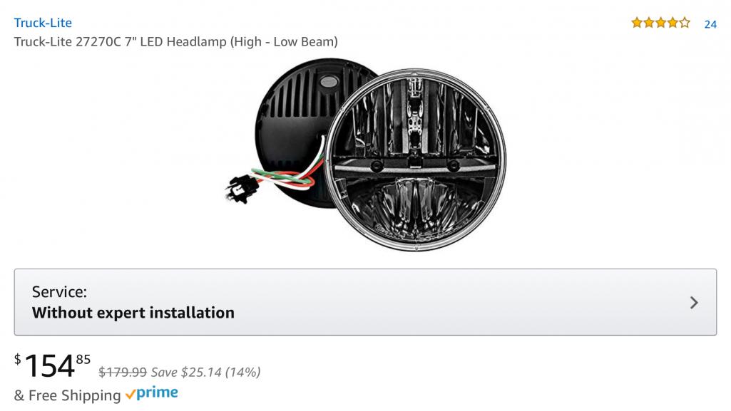
|
|
|
|
| Tbrown4x4 |
Apr 15 2019, 05:02 AM
Post
#16
|
|
Senior Member Group: Members Posts: 708 Joined: 13-May 14 From: Port Orchard, WA Member No.: 17,338 Region Association: None |
Good to know! I think I have these on an Amazon wish list already. I just haven't pulled the trigger yet.
|
|
|
|
| orthobiz |
Apr 15 2019, 03:31 PM
Post
#17
|
|
Senior Member Group: Members Posts: 1,772 Joined: 8-January 07 From: Cadillac, Michigan Member No.: 7,438 Region Association: Upper MidWest |
This is great, thanks. I posted some lens pictures at:
http://www.914world.com/bbs2/index.php?sho...=233202&hl= The early and late lenses have different heights, is that what you meant when you said "early?" More importantly, will this affect the LED project?? I LOVE visibility and have ALL of your stuff!! Paul |
|
|
|
| Mike Bellis |
Apr 15 2019, 07:22 PM
Post
#18
|
|
Resident Electrician Group: Members Posts: 8,348 Joined: 22-June 09 From: Midlothian TX Member No.: 10,496 Region Association: None |
Why not mount the power supply remote in an IP65/67 enclosure mounted behind the 914 grille? It would free up some space and maybe reduce temps inside the light assembly.
|
|
|
|
| Spoke |
Apr 15 2019, 07:49 PM
Post
#19
|
|
Jerry Group: Members Posts: 7,400 Joined: 29-October 04 From: Allentown, PA Member No.: 3,031 Region Association: None |
QUOTE(orthobiz @ Apr 15 2019, 05:31 PM) This is great, thanks. I posted some lens pictures at: http://www.914world.com/bbs2/index.php?sho...=233202&hl= The early and late lenses have different heights, is that what you meant when you said "early?" More importantly, will this affect the LED project?? I LOVE visibility and have ALL of your stuff!! Paul Thanks for the info. My '71 has the early lens which looks to be a bit deeper. After doing some initial measurements on my early lens, I didn't think I'd need a spacer as needed with the later lens. Either way shouldn't be an issue. |
|
|
|
| Spoke |
Apr 15 2019, 07:53 PM
Post
#20
|
|
Jerry Group: Members Posts: 7,400 Joined: 29-October 04 From: Allentown, PA Member No.: 3,031 Region Association: None |
QUOTE(Mike Bellis @ Apr 15 2019, 09:22 PM) Why not mount the power supply remote in an IP65/67 enclosure mounted behind the 914 grille? It would free up some space and maybe reduce temps inside the light assembly. This is what I did for the 356 running lights although the boost converter PCB was mounted inside the housing. I proposed a separate box to put the converter in but the owner didn't want an external box so I mounted on the back of the heatsink. I'd like to keep it to one PCB for simplicity although a separate module may be needed depending on temperature rise. |
|
|
|
|
2 User(s) are reading this topic (2 Guests and 0 Anonymous Users)
0 Members:

|
Lo-Fi Version | Time is now: 8th July 2026 - 07:35 AM |
Invision Power Board
v9.1.4 © 2026 IPS, Inc.