|
|
|
Porsche, and the Porsche crest are registered trademarks of Dr. Ing. h.c. F. Porsche AG.
This site is not affiliated with Porsche in any way. Its only purpose is to provide an online forum for car enthusiasts. All other trademarks are property of their respective owners. |
|
|

  |

| Philippe |
 Dec 22 2019, 04:43 AM Dec 22 2019, 04:43 AM
Post
#1
|
|
Newbie  Group: Members Posts: 14 Joined: 8-December 11 From: Belgium Member No.: 13,877 Region Association: None |
Hi,
Does anybody have a good picture (or wiring diagram) of the main 14-pin harness connector with the cap removed (the one that is connected to the main relay board). I have a brown-white (maybe brown-gray) wire arriving at this connector and have no clue where it plugs in. Even worse...this wire is not referenced in Art Zaft 914-6 wiring diagram. Thanks for any help. Philippe 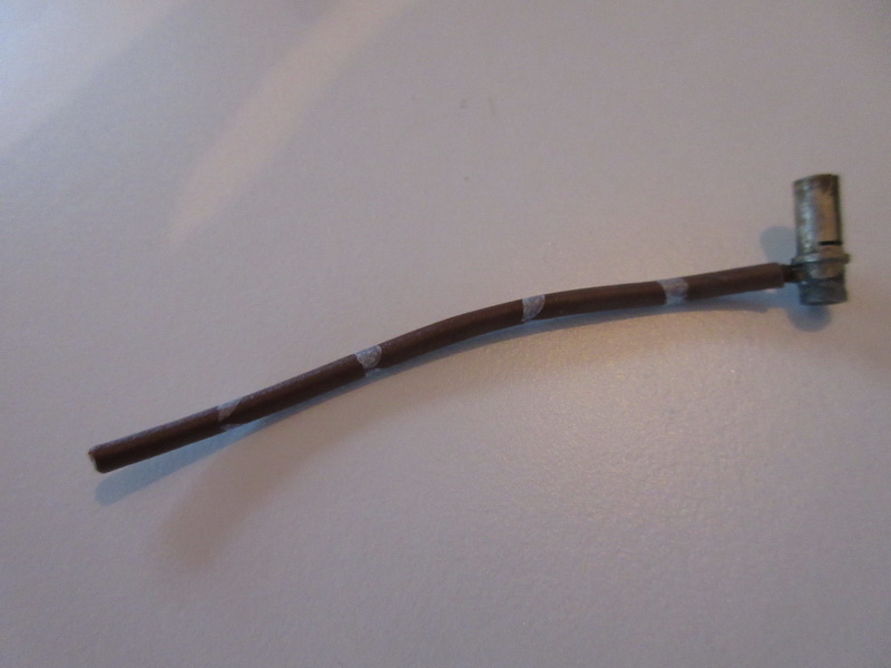 |
   |

 
|
| Rleog |
Dec 22 2019, 06:01 AM
Post
#2
|
|
Senior Member Group: Members Posts: 608 Joined: 12-October 03 From: Middleton, MA Member No.: 1,239 Region Association: North East States |
I don’t intend to confuse here, but this might help. I have a 914-4 wiring diagram that shows a grey/brown wire that runs between the back up lights and T14 terminal 4.
Caution: 914-4 and 914-6 may be different. Check your back up lights and see if they have a grey/brown lead wire. |
|
|
|
| rgalla9146 |
Dec 22 2019, 07:52 AM
Post
#3
|
|
Advanced Member Group: Members Posts: 4,552 Joined: 23-November 05 From: Paramus NJ Member No.: 5,176 Region Association: None |
Both connectors at the 6 relay board are 14 pin.
The one going to the engine harness does not have a wire like your photo. Maybe a Euro feature ? I'll try to access the connector going into the relay board. Attached thumbnail(s) 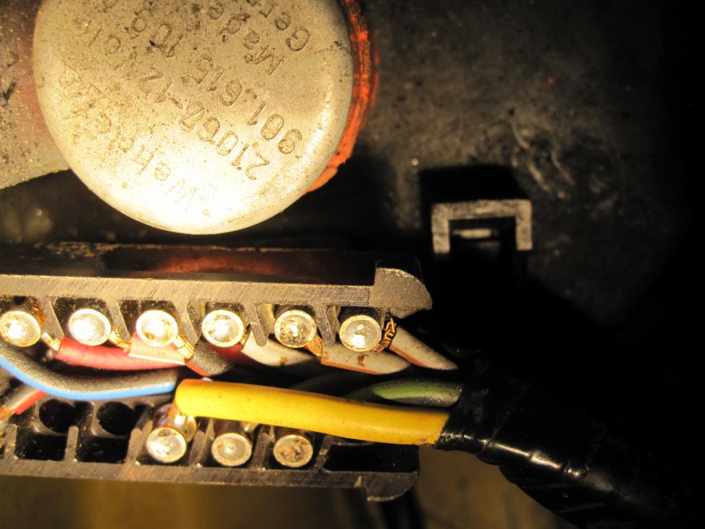
|
|
|
|
| sixnotfour |
Dec 22 2019, 08:40 AM
Post
#4
|
|
914 Wizard Group: Members Posts: 10,430 Joined: 12-September 04 From: Life Elevated..planet UT. Member No.: 2,744 Region Association: Rocky Mountains |
|
|
|
|
| sixnotfour |
Dec 22 2019, 09:01 AM
Post
#5
|
|
914 Wizard Group: Members Posts: 10,430 Joined: 12-September 04 From: Life Elevated..planet UT. Member No.: 2,744 Region Association: Rocky Mountains |
al kosmal added notes
Attached image(s) 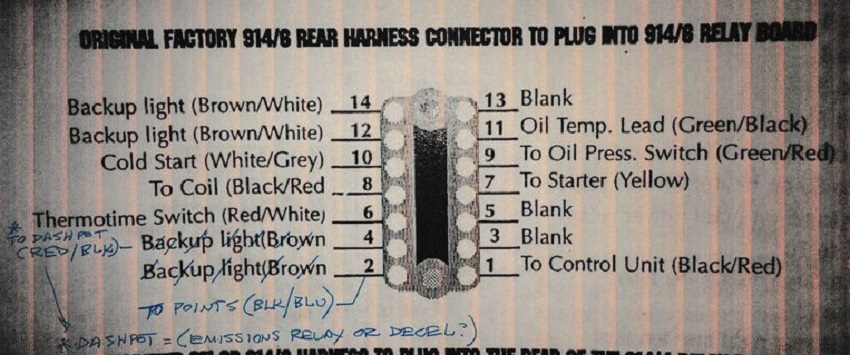
|
|
|
|
| rgalla9146 |
Dec 22 2019, 09:25 AM
Post
#6
|
|
Advanced Member Group: Members Posts: 4,552 Joined: 23-November 05 From: Paramus NJ Member No.: 5,176 Region Association: None |
Chassis into the relay board
don't see a wire like yours in either connector Attached thumbnail(s) 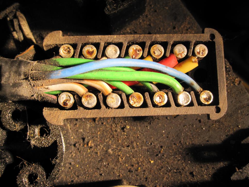 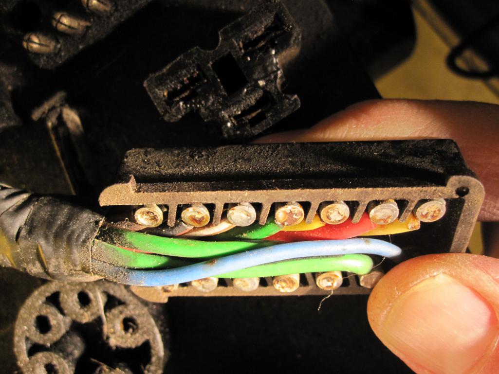
|
|
|
|
| rgalla9146 |
Dec 22 2019, 09:29 AM
Post
#7
|
|
Advanced Member Group: Members Posts: 4,552 Joined: 23-November 05 From: Paramus NJ Member No.: 5,176 Region Association: None |
QUOTE(sixnotfour @ Dec 22 2019, 10:01 AM)  al kosmal added notes Ahhhhh. Thank you for the update. That black/blue wire in my photo had me worried |
|
|
|
| Philippe |
Dec 22 2019, 10:19 AM
Post
#8
|
|
Newbie Group: Members Posts: 14 Joined: 8-December 11 From: Belgium Member No.: 13,877 Region Association: None |
QUOTE(rgalla9146 @ Dec 22 2019, 05:52 AM) Both connectors at the 6 relay board are 14 pin. The one going to the engine harness does not have a wire like your photo. Maybe a Euro feature ? I'll try to access the connector going into the relay board. This is right. I meant the main harness connector and not the engine connector (both having 14 pins). |
|
|
|
| Philippe |
Dec 22 2019, 10:29 AM
Post
#9
|
|
Newbie Group: Members Posts: 14 Joined: 8-December 11 From: Belgium Member No.: 13,877 Region Association: None |
QUOTE(rgalla9146 @ Dec 22 2019, 07:25 AM) Chassis into the relay board don't see a wire like yours in either connector Nice! Thank you. What colour do you have on pin 9 (starting from the top, left side, 5th pin)? |
|
|
|
| Philippe |
Dec 22 2019, 10:36 AM
Post
#10
|
|
Newbie Group: Members Posts: 14 Joined: 8-December 11 From: Belgium Member No.: 13,877 Region Association: None |
So far I come to the following pin assignment (looking at the backside of the connector):
1 Yellow 2. Blue 3. Red 4. Green 5. Yellow/Red 6. Green/Black 7. Green 8. Green/Red 9. Not assigned? 10. Gray/Brown 11. Black/Red 12. Gray/Brown 13. Brown 14. Black/Purple |
|
|
|
| rgalla9146 |
Dec 22 2019, 12:01 PM
Post
#11
|
|
Advanced Member Group: Members Posts: 4,552 Joined: 23-November 05 From: Paramus NJ Member No.: 5,176 Region Association: None |
QUOTE(Philippe @ Dec 22 2019, 11:29 AM) QUOTE(rgalla9146 @ Dec 22 2019, 07:25 AM) Chassis into the relay board don't see a wire like yours in either connector Nice! Thank you. What colour do you have on pin 9 (starting from the top, left side, 5th pin)? Appears to be brown with white tracer |
|
|
|
| Luke M |
Dec 22 2019, 01:00 PM
Post
#12
|
|
Senior Member Group: Members Posts: 1,371 Joined: 8-February 05 From: WNY Member No.: 3,574 Region Association: North East States |
QUOTE(rgalla9146 @ Dec 22 2019, 11:01 AM) QUOTE(Philippe @ Dec 22 2019, 11:29 AM) QUOTE(rgalla9146 @ Dec 22 2019, 07:25 AM) Chassis into the relay board don't see a wire like yours in either connector Nice! Thank you. What colour do you have on pin 9 (starting from the top, left side, 5th pin)? Appears to be brown with white tracer I just checked my factory 6 and my new Kroon wire harnesses. Both brown with a white tracer go to pin #9. Attached image(s) 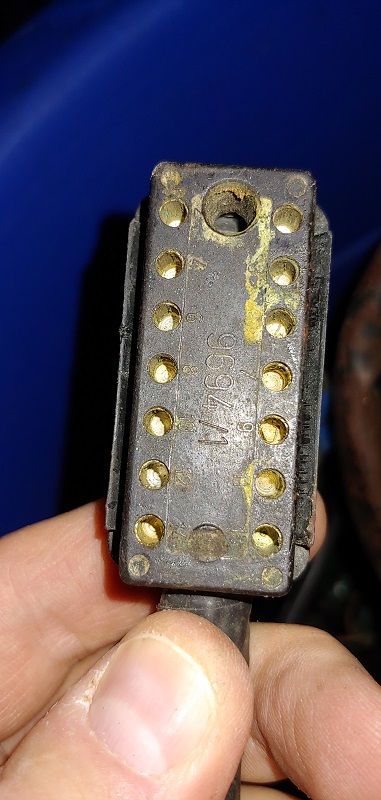 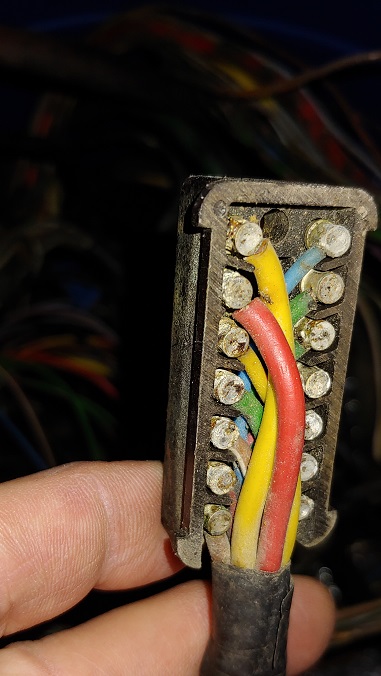  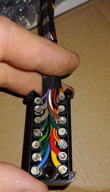
|
|
|
|
| rgalla9146 |
Dec 22 2019, 02:17 PM
Post
#13
|
|
Advanced Member Group: Members Posts: 4,552 Joined: 23-November 05 From: Paramus NJ Member No.: 5,176 Region Association: None |
Wow.
Note to self; schedule thorough harness cleaning |
|
|
|
| toolguy |
Dec 22 2019, 03:29 PM
Post
#14
|
|
Senior Member Group: Members Posts: 1,267 Joined: 2-April 11 From: San Diego / El Cajon Member No.: 12,889 Region Association: Southern California |
As i remember, there are a couple [2] of wiring color code errors on the 914-6 relay board in the Art Zaft diagram
|
|
|
|
| Philippe |
Dec 23 2019, 02:47 AM
Post
#15
|
|
Newbie Group: Members Posts: 14 Joined: 8-December 11 From: Belgium Member No.: 13,877 Region Association: None |
QUOTE(Luke M @ Dec 22 2019, 11:00 AM) QUOTE(rgalla9146 @ Dec 22 2019, 11:01 AM) QUOTE(Philippe @ Dec 22 2019, 11:29 AM) QUOTE(rgalla9146 @ Dec 22 2019, 07:25 AM) Chassis into the relay board don't see a wire like yours in either connector Nice! Thank you. What colour do you have on pin 9 (starting from the top, left side, 5th pin)? Appears to be brown with white tracer I just checked my factory 6 and my new Kroon wire harnesses. Both brown with a white tracer goes to pin #9. Thanks a lot for the nice pics. I have the answer to my question! Even if the tracer is different, the basic brown/white colour of pin 9 remains the same. What still bothers me is the fact that this brown/white wire is not documented. BTW Kroon did an excellent job. The welding work at the connector is well done. Thanks to you all for the support. Philippe |
|
|
|
| altitude411 |
Dec 23 2019, 08:07 PM
Post
#16
|
|
I drove my 6 into a tree Group: Members Posts: 1,306 Joined: 21-September 14 From: montana Member No.: 17,932 Region Association: Rocky Mountains |
I have wire harness envy... (IMG:style_emoticons/default/shades.gif)
|
|
|
|
| gerakroo |
Mar 20 2020, 03:27 AM
Post
#17
|
|
Newbie Group: Members Posts: 15 Joined: 27-June 14 From: Sappemeer Member No.: 17,563 Region Association: Europe |
QUOTE(Philippe @ Dec 23 2019, 09:47 AM) QUOTE(Luke M @ Dec 22 2019, 11:00 AM) QUOTE(rgalla9146 @ Dec 22 2019, 11:01 AM) QUOTE(Philippe @ Dec 22 2019, 11:29 AM) QUOTE(rgalla9146 @ Dec 22 2019, 07:25 AM) Chassis into the relay board don't see a wire like yours in either connector Nice! Thank you. What colour do you have on pin 9 (starting from the top, left side, 5th pin)? Appears to be brown with white tracer I just checked my factory 6 and my new Kroon wire harnesses. Both brown with a white tracer goes to pin #9. Thanks a lot for the nice pics. I have the answer to my question! Even if the tracer is different, the basic brown/white colour of pin 9 remains the same. What still bothers me is the fact that this brown/white wire is not documented. BTW Kroon did an excellent job. The welding work at the connector is well done. Thanks to you all for the support. Philippe Thank you ! |
|
|
|
| rgalla9146 |
Mar 20 2020, 07:54 AM
Post
#18
|
|
Advanced Member Group: Members Posts: 4,552 Joined: 23-November 05 From: Paramus NJ Member No.: 5,176 Region Association: None |
Well a year and three months later (almost to the day) i believe I have the answer.
It is the wire for the switch incorporated in the shift knob of Sportomatic cars. The white car harness is re-wrapped. The yellow is untouched. Attached thumbnail(s) 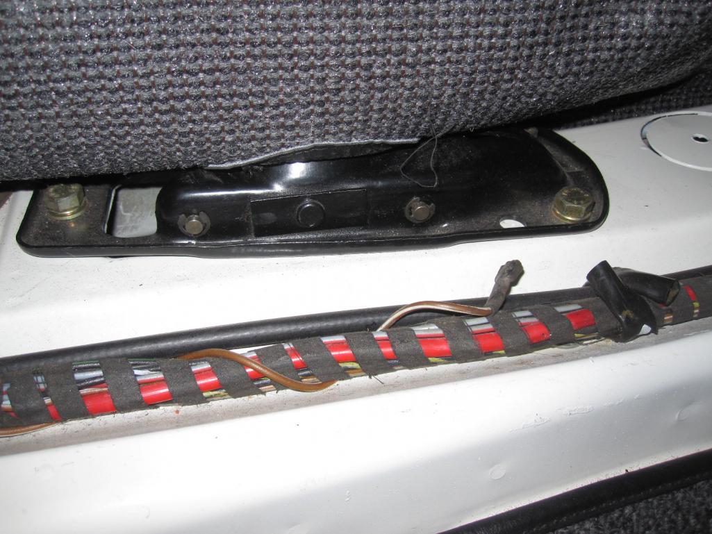 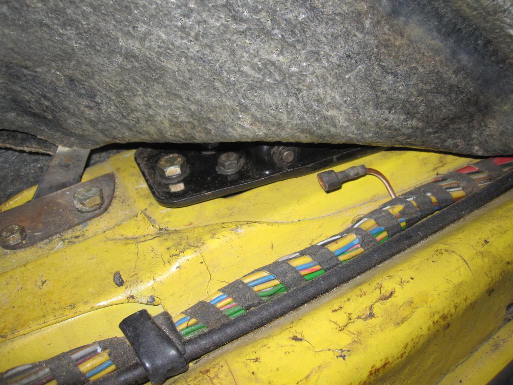
|
|
|
|
| dr914@autoatlanta.com |
Mar 20 2020, 09:00 AM
Post
#19
|
|
914 Guru Group: Members Posts: 7,857 Joined: 3-January 07 From: atlanta georgia Member No.: 7,418 Region Association: None |
I agree, there is a factory six factory drawn wiring diagram out there, we have enlarged copies of it
QUOTE(Rleog @ Dec 22 2019, 05:01 AM) I don’t intend to confuse here, but this might help. I have a 914-4 wiring diagram that shows a grey/brown wire that runs between the back up lights and T14 terminal 4. Caution: 914-4 and 914-6 may be different. Check your back up lights and see if they have a grey/brown lead wire. |
|
|
|
| rgalla9146 |
Mar 20 2020, 09:56 AM
Post
#20
|
|
Advanced Member Group: Members Posts: 4,552 Joined: 23-November 05 From: Paramus NJ Member No.: 5,176 Region Association: None |
QUOTE(dr914@autoatlanta.com @ Mar 20 2020, 11:00 AM) I agree, there is a factory six factory drawn wiring diagram out there, we have enlarged copies of it QUOTE(Rleog @ Dec 22 2019, 05:01 AM) I don’t intend to confuse here, but this might help. I have a 914-4 wiring diagram that shows a grey/brown wire that runs between the back up lights and T14 terminal 4. Caution: 914-4 and 914-6 may be different. Check your back up lights and see if they have a grey/brown lead wire. ....what is it that you agree with ? |
|
|
|
|
1 User(s) are reading this topic (1 Guests and 0 Anonymous Users)
0 Members:

|
Lo-Fi Version | Time is now: 15th May 2024 - 05:23 PM |
Invision Power Board
v9.1.4 © 2024 IPS, Inc.