|
|
|
Porsche, and the Porsche crest are registered trademarks of Dr. Ing. h.c. F. Porsche AG.
This site is not affiliated with Porsche in any way. Its only purpose is to provide an online forum for car enthusiasts. All other trademarks are property of their respective owners. |
|
|


| mgarrison |
 Feb 29 2020, 09:54 AM Feb 29 2020, 09:54 AM
Post
#381
|
|
Member  Group: Members Posts: 416 Joined: 14-February 20 From: Chandler, AZ Member No.: 23,922 Region Association: Southwest Region |
Hello,
I new around here, but have been lurking for a bit trying to soak up all the 914 knowledge and information I could! I was looking into building a Factory Five 818 kit with the Subaru flat-4, but the cost of entry was a bit too high, and the time & space needed to build a car from scratch seemed overwhelming. But it got me thinking; that's basically a tube-framed 914 with an odd body. I wonder if anyone has put a Subaru flat-4 in a 914? A few Google searches later I learned that a lot of people had, and parts were out there to spend my money on! Long story short, I found two rollers with no engines or transmissions in Tucson, AZ a couple of hours South of me. Soon I rented a car hauler for a couple of days and my "Craft Project" (my wife's label) was begun. The rollers were a green 1971, and a red 1974. I wanted to restore the 71 because it just seemed to have more character. The 74 had been partially stripped for an electric conversion project, and seemed less "car like". Sadly, the 71 needed a bit more work than I was setup to handle. So, it had to be the 74 who I have simply labeled as "Red". I will try to track my build process here as best I can. I tend to get working on things and forget to document things, but will try to keep track. Here's Red when we got her home on the trailer and tucked away in the back yard for the moment. Mike 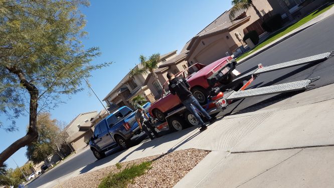 Attached image(s) 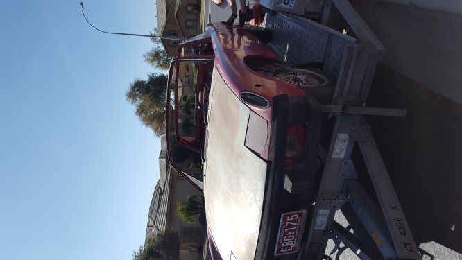
|
   |

 
|
Posts in this topic
mgarrison 74 Roller rebuild and Subaru conversion Feb 29 2020, 09:54 AM mgarrison If anyone knows how to correctly rotate portrait i... Feb 29 2020, 09:56 AM mgarrison We got Red tucked away in the back yard so that we... Feb 29 2020, 10:01 AM mgarrison Here is her temporary home until I decided she was... Feb 29 2020, 10:02 AM mgarrison Once I got Red squared away in my working area, I ... Feb 29 2020, 10:08 AM mgarrison I managed to get the headlight assemblies all out,... Feb 29 2020, 10:25 AM Mueller The red car does look solid, I wish my car was a ... Feb 29 2020, 10:27 AM JRust Welcome to the madness. There are quite a few suby... Feb 29 2020, 10:36 AM
 mgarrison
Welcome to the madness. There are quite a few sub... Feb 29 2020, 11:43 AM Thunderchief Is it hard to get the headlight assembly out? I ne... Feb 29 2020, 10:44 AM mgarrison
Is it hard to get the headlight assembly out? I n... Feb 29 2020, 11:41 AM GermermanCarGuy I, too, am currently in the process of doing a sub... Feb 29 2020, 04:34 PM mgarrison After some wasted time repairing a sprinkler valve... Feb 29 2020, 09:15 PM mgarrison Since all my garage space is taken up already, I h... Feb 29 2020, 09:20 PM mgarrison I did manage to get the pedal cluster out. Quite a... Feb 29 2020, 09:26 PM mgarrison I also pulled the read trunk lid off so I could re... Feb 29 2020, 09:30 PM billh1963 You are starting with a very solid car....congratu... Mar 1 2020, 05:46 AM Mayne Looks like you’re having fun! Keep posting s... Mar 1 2020, 08:28 AM Literati914
..
Does anybody have any amazing, creative ideas ... Mar 1 2020, 10:52 AM mgarrison Didn't seem like I got much done today, but I... Mar 1 2020, 10:02 PM mgarrison I got distracted for about a week fab'ing up a... Mar 9 2020, 01:01 PM 76-914 Nice job. Throw a couple of sheets of plywood over... Mar 10 2020, 10:41 AM mgarrison Finally got back to the '14 after being distra... Apr 2 2020, 03:43 PM mgarrison Got the tar off the floor pan fairly easy, but tha... Apr 2 2020, 03:49 PM mgarrison A bit of surface rust near the pedal box. Does not... Apr 2 2020, 03:57 PM mgarrison I want to run my radiator hoses through the longs ... Apr 2 2020, 04:05 PM mgarrison Not really sure what to say about some of these fa... Apr 2 2020, 04:09 PM Cairo94507 I sometimes think that stress crack at the handbra... Apr 2 2020, 04:28 PM 76-914 The interior view of those longs looks cherry. Are... Apr 2 2020, 09:12 PM mgarrison
The interior view of those longs looks cherry. Ar... Apr 3 2020, 11:13 AM mgarrison It's been a long time since I updated this - b... Nov 5 2020, 01:22 PM mgarrison A couple more pics of suspension/brake stuff. I di... Nov 5 2020, 01:44 PM mgarrison Finally getting around to posting another update... Dec 20 2020, 10:43 AM 76-914 You're making good progress. I've got mixe... Dec 20 2020, 12:31 PM mgarrison
You're making good progress. I've got mix... Dec 21 2020, 09:00 AM 76-914
You're making good progress. I've got mi... Dec 21 2020, 12:10 PM IM101
[quote name='mgarrison' post='2876903' date='Dec ... Dec 21 2020, 12:23 PM rhodyguy A painters '5 in 1' tool and the heat gun ... Dec 20 2020, 03:29 PM Costa05
A painters '5 in 1' tool and the heat gun... Dec 20 2020, 04:44 PM mgarrison A few more pics of yesterday's work.
Here... Dec 21 2020, 09:08 AM mgarrison Finished another patch section. Right side was dif... Dec 22 2020, 01:59 PM mgarrison Completed one more small patch. Was a total PITA t... Dec 23 2020, 05:40 PM djway I hear ya on the supposed to get better with pract... Dec 23 2020, 06:22 PM mgarrison Another small update. Progress seems SO SLOW, but ... Dec 30 2020, 09:56 AM mgarrison I've been taking pictures as I work, but getti... Jan 16 2021, 11:00 AM 914forme You need a sealer step for the paint and even then... Jan 16 2021, 09:43 PM 76-914
You need a sealer step for the paint and even the... Jan 16 2021, 09:46 PM mb911
You need a sealer step for the paint and even th... Jan 17 2021, 07:26 AM mgarrison Thanks guys. Its an inexpensive, gasless, DC inver... Jan 17 2021, 09:15 AM mb911
Thanks guys. Its an inexpensive, gasless, DC inve... Jan 17 2021, 12:29 PM tazz9924
Thanks guys. Its an inexpensive, gasless, DC inv... Jan 18 2021, 02:09 PM mgarrison A little more progress, I guess. Struggling with t... Jan 24 2021, 09:51 AM mb911 Well remember you are using flux core on sheet met... Jan 24 2021, 10:14 AM mgarrison Tack weld question; when you are tacking sheet met... Jan 25 2021, 03:16 PM mb911 No circling for what your tacking Jan 25 2021, 03:35 PM Cairo94507 @mgarrison - Here are a few photos of my e-brake ... Jan 25 2021, 03:46 PM djway Check all the connections on your welder.
Especial... Jan 25 2021, 11:21 PM mgarrison Thanks for the tips guys! I'm going to pra... Jan 26 2021, 09:45 AM mgarrison More trunk work - that took a lot longer than I an... Feb 3 2021, 04:39 PM mgarrison The last thing I did last night was check the weat... Feb 3 2021, 07:39 PM JRust Looking great bud. Keep up the good work Feb 3 2021, 08:11 PM 2mAn Great build. Moving slow, but you're doing it ... Feb 4 2021, 11:08 AM mgarrison Does anyone know if these two holes should be ther... Feb 4 2021, 07:20 PM mgarrison While I'm waiting for more weld-thru primer to... Feb 5 2021, 07:06 PM dakotaewing Your moving along nicely! Just a friendly remi... Feb 5 2021, 09:30 PM mgarrison Thanks for the advice/reminder! I ran down to ... Feb 6 2021, 03:48 PM mgarrison I got each and every hole filled with a screw, and... Feb 13 2021, 08:37 PM 2mAn Loving this thread, keep it up Feb 14 2021, 01:25 AM mgarrison Ran to HD early (to avoid people) this morning to ... Feb 14 2021, 09:44 PM djway Looks great. Feb 14 2021, 10:37 PM 76-914 You need a copper backing plate to help with the s... Feb 15 2021, 09:13 AM mgarrison I've got some smashed copper pipe to use as ba... Feb 15 2021, 06:41 PM mgarrison Today was mostly washing/cleaning up my truck, but... Feb 15 2021, 06:45 PM djway Does it feel stiffer? :) Feb 15 2021, 10:18 PM mgarrison Impossible to tell...no suspension, wheels, etc.... Feb 16 2021, 09:43 AM mgarrison I got the panels all stitched in. Things were goin... Feb 18 2021, 07:39 PM seanpaulmc Great job!!! :Qarl:
Is there any st... Feb 18 2021, 07:55 PM mgarrison
Great job!!! :Qarl:
Is there any s... Feb 26 2021, 08:34 PM mgarrison Still just trying to keep moving forward. Inch by ... Feb 26 2021, 09:02 PM mgarrison I wire brushed the vent holes as best I could and ... Feb 27 2021, 08:12 PM mgarrison I've been working along slowly. Just keep swim... Mar 21 2021, 02:38 PM mgarrison I was really struggling trying to figure out how t... Apr 7 2021, 10:30 AM mgarrison Been plugging along slowly. Finished up the frunk,... Apr 11 2021, 02:41 PM mgarrison I got the block off plates from Mad Dog Motorsport... Apr 16 2021, 09:30 PM mgarrison Working on reusing/repurposing the fender braces o... Apr 20 2021, 10:11 AM 76-914 Using those butt-weld clamps as a 3rd hand was a g... Apr 20 2021, 07:29 PM mgarrison
Using those butt-weld clamps as a 3rd hand was a ... Jun 1 2021, 10:26 AM mgarrison I've been making small/slow progress. I just k... Jun 1 2021, 10:51 AM 76-914 You will finish the project quicker when working o... Jun 2 2021, 09:04 AM mgarrison Finally got my filter/dryer delivered and installe... Jun 10 2021, 04:43 PM mgarrison Started before 6am to try and spray at least one q... Jun 15 2021, 09:32 AM 76-914 Looks great. What size tip did you use? I don... Jun 15 2021, 12:00 PM mgarrison I just used the Schutz gun that came with the Rapt... Jun 15 2021, 12:57 PM mgarrison I've been spraying one quart each morning befo... Jun 17 2021, 10:16 AM Costa05
I've been spraying one quart each morning bef... Jun 17 2021, 10:31 AM mgarrison So, the Raptor coating did not hide my patches/rep... Jun 28 2021, 09:54 AM mgarrison Finally had a morning with little wind, so I gave ... Jul 4 2021, 06:02 PM Mayne Impressive work! Are you going to spray the ar... Jul 5 2021, 06:17 AM mgarrison Most likely will leave them black. But, if after I... Jul 5 2021, 12:01 PM Mowog4 I am enjoying the build, I am in Mesa with a simil... Jul 8 2021, 09:10 PM
mgarrison
Welcome to the madness. There are quite a few sub... Feb 29 2020, 11:43 AM Thunderchief Is it hard to get the headlight assembly out? I ne... Feb 29 2020, 10:44 AM mgarrison
Is it hard to get the headlight assembly out? I n... Feb 29 2020, 11:41 AM GermermanCarGuy I, too, am currently in the process of doing a sub... Feb 29 2020, 04:34 PM mgarrison After some wasted time repairing a sprinkler valve... Feb 29 2020, 09:15 PM mgarrison Since all my garage space is taken up already, I h... Feb 29 2020, 09:20 PM mgarrison I did manage to get the pedal cluster out. Quite a... Feb 29 2020, 09:26 PM mgarrison I also pulled the read trunk lid off so I could re... Feb 29 2020, 09:30 PM billh1963 You are starting with a very solid car....congratu... Mar 1 2020, 05:46 AM Mayne Looks like you’re having fun! Keep posting s... Mar 1 2020, 08:28 AM Literati914
..
Does anybody have any amazing, creative ideas ... Mar 1 2020, 10:52 AM mgarrison Didn't seem like I got much done today, but I... Mar 1 2020, 10:02 PM mgarrison I got distracted for about a week fab'ing up a... Mar 9 2020, 01:01 PM 76-914 Nice job. Throw a couple of sheets of plywood over... Mar 10 2020, 10:41 AM mgarrison Finally got back to the '14 after being distra... Apr 2 2020, 03:43 PM mgarrison Got the tar off the floor pan fairly easy, but tha... Apr 2 2020, 03:49 PM mgarrison A bit of surface rust near the pedal box. Does not... Apr 2 2020, 03:57 PM mgarrison I want to run my radiator hoses through the longs ... Apr 2 2020, 04:05 PM mgarrison Not really sure what to say about some of these fa... Apr 2 2020, 04:09 PM Cairo94507 I sometimes think that stress crack at the handbra... Apr 2 2020, 04:28 PM 76-914 The interior view of those longs looks cherry. Are... Apr 2 2020, 09:12 PM mgarrison
The interior view of those longs looks cherry. Ar... Apr 3 2020, 11:13 AM mgarrison It's been a long time since I updated this - b... Nov 5 2020, 01:22 PM mgarrison A couple more pics of suspension/brake stuff. I di... Nov 5 2020, 01:44 PM mgarrison Finally getting around to posting another update... Dec 20 2020, 10:43 AM 76-914 You're making good progress. I've got mixe... Dec 20 2020, 12:31 PM mgarrison
You're making good progress. I've got mix... Dec 21 2020, 09:00 AM 76-914
You're making good progress. I've got mi... Dec 21 2020, 12:10 PM IM101
[quote name='mgarrison' post='2876903' date='Dec ... Dec 21 2020, 12:23 PM rhodyguy A painters '5 in 1' tool and the heat gun ... Dec 20 2020, 03:29 PM Costa05
A painters '5 in 1' tool and the heat gun... Dec 20 2020, 04:44 PM mgarrison A few more pics of yesterday's work.
Here... Dec 21 2020, 09:08 AM mgarrison Finished another patch section. Right side was dif... Dec 22 2020, 01:59 PM mgarrison Completed one more small patch. Was a total PITA t... Dec 23 2020, 05:40 PM djway I hear ya on the supposed to get better with pract... Dec 23 2020, 06:22 PM mgarrison Another small update. Progress seems SO SLOW, but ... Dec 30 2020, 09:56 AM mgarrison I've been taking pictures as I work, but getti... Jan 16 2021, 11:00 AM 914forme You need a sealer step for the paint and even then... Jan 16 2021, 09:43 PM 76-914
You need a sealer step for the paint and even the... Jan 16 2021, 09:46 PM mb911
You need a sealer step for the paint and even th... Jan 17 2021, 07:26 AM mgarrison Thanks guys. Its an inexpensive, gasless, DC inver... Jan 17 2021, 09:15 AM mb911
Thanks guys. Its an inexpensive, gasless, DC inve... Jan 17 2021, 12:29 PM tazz9924
Thanks guys. Its an inexpensive, gasless, DC inv... Jan 18 2021, 02:09 PM mgarrison A little more progress, I guess. Struggling with t... Jan 24 2021, 09:51 AM mb911 Well remember you are using flux core on sheet met... Jan 24 2021, 10:14 AM mgarrison Tack weld question; when you are tacking sheet met... Jan 25 2021, 03:16 PM mb911 No circling for what your tacking Jan 25 2021, 03:35 PM Cairo94507 @mgarrison - Here are a few photos of my e-brake ... Jan 25 2021, 03:46 PM djway Check all the connections on your welder.
Especial... Jan 25 2021, 11:21 PM mgarrison Thanks for the tips guys! I'm going to pra... Jan 26 2021, 09:45 AM mgarrison More trunk work - that took a lot longer than I an... Feb 3 2021, 04:39 PM mgarrison The last thing I did last night was check the weat... Feb 3 2021, 07:39 PM JRust Looking great bud. Keep up the good work Feb 3 2021, 08:11 PM 2mAn Great build. Moving slow, but you're doing it ... Feb 4 2021, 11:08 AM mgarrison Does anyone know if these two holes should be ther... Feb 4 2021, 07:20 PM mgarrison While I'm waiting for more weld-thru primer to... Feb 5 2021, 07:06 PM dakotaewing Your moving along nicely! Just a friendly remi... Feb 5 2021, 09:30 PM mgarrison Thanks for the advice/reminder! I ran down to ... Feb 6 2021, 03:48 PM mgarrison I got each and every hole filled with a screw, and... Feb 13 2021, 08:37 PM 2mAn Loving this thread, keep it up Feb 14 2021, 01:25 AM mgarrison Ran to HD early (to avoid people) this morning to ... Feb 14 2021, 09:44 PM djway Looks great. Feb 14 2021, 10:37 PM 76-914 You need a copper backing plate to help with the s... Feb 15 2021, 09:13 AM mgarrison I've got some smashed copper pipe to use as ba... Feb 15 2021, 06:41 PM mgarrison Today was mostly washing/cleaning up my truck, but... Feb 15 2021, 06:45 PM djway Does it feel stiffer? :) Feb 15 2021, 10:18 PM mgarrison Impossible to tell...no suspension, wheels, etc.... Feb 16 2021, 09:43 AM mgarrison I got the panels all stitched in. Things were goin... Feb 18 2021, 07:39 PM seanpaulmc Great job!!! :Qarl:
Is there any st... Feb 18 2021, 07:55 PM mgarrison
Great job!!! :Qarl:
Is there any s... Feb 26 2021, 08:34 PM mgarrison Still just trying to keep moving forward. Inch by ... Feb 26 2021, 09:02 PM mgarrison I wire brushed the vent holes as best I could and ... Feb 27 2021, 08:12 PM mgarrison I've been working along slowly. Just keep swim... Mar 21 2021, 02:38 PM mgarrison I was really struggling trying to figure out how t... Apr 7 2021, 10:30 AM mgarrison Been plugging along slowly. Finished up the frunk,... Apr 11 2021, 02:41 PM mgarrison I got the block off plates from Mad Dog Motorsport... Apr 16 2021, 09:30 PM mgarrison Working on reusing/repurposing the fender braces o... Apr 20 2021, 10:11 AM 76-914 Using those butt-weld clamps as a 3rd hand was a g... Apr 20 2021, 07:29 PM mgarrison
Using those butt-weld clamps as a 3rd hand was a ... Jun 1 2021, 10:26 AM mgarrison I've been making small/slow progress. I just k... Jun 1 2021, 10:51 AM 76-914 You will finish the project quicker when working o... Jun 2 2021, 09:04 AM mgarrison Finally got my filter/dryer delivered and installe... Jun 10 2021, 04:43 PM mgarrison Started before 6am to try and spray at least one q... Jun 15 2021, 09:32 AM 76-914 Looks great. What size tip did you use? I don... Jun 15 2021, 12:00 PM mgarrison I just used the Schutz gun that came with the Rapt... Jun 15 2021, 12:57 PM mgarrison I've been spraying one quart each morning befo... Jun 17 2021, 10:16 AM Costa05
I've been spraying one quart each morning bef... Jun 17 2021, 10:31 AM mgarrison So, the Raptor coating did not hide my patches/rep... Jun 28 2021, 09:54 AM mgarrison Finally had a morning with little wind, so I gave ... Jul 4 2021, 06:02 PM Mayne Impressive work! Are you going to spray the ar... Jul 5 2021, 06:17 AM mgarrison Most likely will leave them black. But, if after I... Jul 5 2021, 12:01 PM Mowog4 I am enjoying the build, I am in Mesa with a simil... Jul 8 2021, 09:10 PM  |
2 User(s) are reading this topic (2 Guests and 0 Anonymous Users)
0 Members:

|
Lo-Fi Version | Time is now: 11th June 2026 - 04:56 PM |
Invision Power Board
v9.1.4 © 2026 IPS, Inc.