|
|
|
Porsche, and the Porsche crest are registered trademarks of Dr. Ing. h.c. F. Porsche AG.
This site is not affiliated with Porsche in any way. Its only purpose is to provide an online forum for car enthusiasts. All other trademarks are property of their respective owners. |
|
|


| RichPugh |
 May 10 2020, 04:29 PM May 10 2020, 04:29 PM
Post
#41
|
|
Member  Group: Members Posts: 132 Joined: 28-October 14 From: Baltimore, MD Member No.: 18,068 Region Association: MidAtlantic Region |
So... the engine is in (I’m using the NaroEscape -6 front mount) and, seeming because of the mount, it sits lower than stock. The Patrick Motorsport -6 shift linkage rod I intended on using, wont work. It interferes with the engine case and doesn’t seem to have a workaround. If the engine were 1/4” - 1/2” higher at the firewall, it looks like it would slip in, but alas, the engine is not going anywhere, lol.
I’m tempted to just bend the PMS bar end upward (maybe a couple inches from where it goes from the narrow shank to the bar rod) to give it the clearance but that would change the angle it goes into the rear bushing and connects to the shift lever... so I figured I’d ask if anyone else had an issue with the bar hitting the engine case and any options I might have. I’m OK with modding the old -4 rod too. Might be worth a shot but figured I’d ask here first. The other threads I found look like the stock rod modded is the move. Thanks Rich 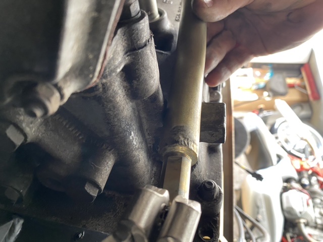 |
   |

 
|
Posts in this topic
 RichPugh 914-6 Conversion Shift Linkage Question May 10 2020, 04:29 PM
 Coondog I would call James Patrick on Monday. He had to be... May 10 2020, 04:49 PM porschetub
So... the engine is in (I’m using the NaroEscap... May 10 2020, 05:37 PM Mark Henry Good job I also built my own shift rod, this is th... May 11 2020, 05:59 PM roblav1 My conversion side shifter mechanism was a straigh... May 11 2020, 07:59 PM Retroracer I purchased the PMS shift rod for my -6 conversion... May 11 2020, 10:04 PM sixnotfour Looks like they are needing some dimensional guida... May 11 2020, 10:24 PM sixnotfour :blink:Naro needs to post about this..Most want fa... May 17 2020, 11:17 AM RichPugh Thanks everyone. Just getting back around to this ... Sep 20 2020, 06:43 PM RichPugh Maybe something like this...
Sep 20 2020, 06:44 PM mb911 I had the same issue with a conversion I did for a... Sep 21 2020, 05:39 AM
Coondog I would call James Patrick on Monday. He had to be... May 10 2020, 04:49 PM porschetub
So... the engine is in (I’m using the NaroEscap... May 10 2020, 05:37 PM Mark Henry Good job I also built my own shift rod, this is th... May 11 2020, 05:59 PM roblav1 My conversion side shifter mechanism was a straigh... May 11 2020, 07:59 PM Retroracer I purchased the PMS shift rod for my -6 conversion... May 11 2020, 10:04 PM sixnotfour Looks like they are needing some dimensional guida... May 11 2020, 10:24 PM sixnotfour :blink:Naro needs to post about this..Most want fa... May 17 2020, 11:17 AM RichPugh Thanks everyone. Just getting back around to this ... Sep 20 2020, 06:43 PM RichPugh Maybe something like this...
Sep 20 2020, 06:44 PM mb911 I had the same issue with a conversion I did for a... Sep 21 2020, 05:39 AM
 JOEPROPER
I had the same issue with a conversion I did for ... Sep 21 2020, 07:20 AM mb911 I would highly recommend it .. I personally have n... Sep 21 2020, 07:35 AM RichPugh
I would highly recommend it .. I personally have ... Sep 21 2020, 08:13 AM PanelBilly I’m using my oem rod but rotated it so it clear... Sep 21 2020, 08:47 AM live free & drive I'm dealing with this same issue right now. I... Sep 21 2020, 09:55 AM mb911 I do have a fixture to modify the stock rod if you... Sep 21 2020, 11:58 AM RichPugh https://youtu.be/62qQqz_GOT4 Sep 21 2020, 08:42 PM RichPugh I thought it was hitting one of the header pipes b... Sep 21 2020, 08:46 PM RichPugh Anyone else using a stock -4 bar just clocked/re-i... Sep 24 2020, 11:27 AM IronHillRestorations You can't use a stock 4 side shift bar as is i... Sep 24 2020, 12:05 PM RichPugh
You can't use a stock 4 side shift bar as is ... Sep 24 2020, 01:34 PM mb911
You can't use a stock 4 side shift bar as is... Sep 24 2020, 02:32 PM gandalf_025 I have a friend that bought the Naro mount and
de... Sep 24 2020, 12:41 PM JOEPROPER This is disappointing. Maybe the Naro Racing peop... Sep 24 2020, 02:28 PM live free & drive I don't know if you all have seen these posts ... Sep 24 2020, 04:43 PM RichPugh
I don't know if you all have seen these posts... Sep 24 2020, 08:50 PM nditiz1 @richpugh I have a modified shift shaft that Ben ... Sep 24 2020, 06:18 PM RichPugh
[b]@[url=http://www.914world.com/bbs2/index.php?s... Sep 24 2020, 08:43 PM JmuRiz I’m sure I’ll send my /4 rod to Ben....maybe i... Sep 24 2020, 09:39 PM nditiz1 I will be around all weekend. Shoot me a PM with ... Sep 24 2020, 09:42 PM mb911 Rich and Nick the only issue with using that linka... Sep 25 2020, 04:28 AM RichPugh
Rich and Nick the only issue with using that link... Sep 25 2020, 06:39 PM RichPugh So... Something like this would work. Ignore the ... Sep 25 2020, 07:41 PM nditiz1 Understood Ben. So do you have two jigs, one for ... Sep 25 2020, 06:11 AM mb911
Understood Ben. So do you have two jigs, one for... Sep 25 2020, 07:26 AM Tdskip Oh boy - I was planning on welding in the Naro Mo... Sep 25 2020, 09:02 AM mb911
Oh boy - I was planning on welding in the Naro M... Sep 25 2020, 09:15 AM RichPugh
Oh boy - I was planning on welding in the Naro ... Sep 25 2020, 06:15 PM Mark Henry I made my own RJ copy mount*, I mounted the bulkhe... Sep 25 2020, 10:09 AM mb911
I made my own RJ copy mount, I mounted the bulkhe... Sep 25 2020, 10:14 AM Mark Henry
That is what I did with my 1st conversion.. This... Sep 25 2020, 10:21 AM RichPugh
Lesson learned. Listening to the manufacturers ... Sep 25 2020, 06:32 PM porschetub
Lesson learned. Listening to the manufacturers... Oct 2 2020, 05:30 PM Mark Henry
I mounted the bulkhead mount to the motor, then I... Sep 30 2020, 10:55 AM RichPugh
Did you have to relocate the rear brake bias uni... Sep 30 2020, 11:13 AM Mark Henry
Did you have to relocate the rear brake bias un... Sep 30 2020, 11:29 AM Steve
Did you have to relocate the rear brake bias u... Sep 30 2020, 11:53 AM Mark Henry
AFAIK vellios (rip) designed the mount first and... Sep 30 2020, 12:35 PM nditiz1 @tdskip try to return the naroscape if you can an... Sep 25 2020, 12:16 PM JOEPROPER
[b]@[url=http://www.914world.com/bbs2/index.php?s... Sep 25 2020, 01:01 PM RichPugh
:thumbsup: Sep 25 2020, 06:33 PM RichPugh
Rich and Nick the only issue with using that link... Sep 28 2020, 03:45 PM mb911
Rich and Nick the only issue with using that lin... Sep 28 2020, 04:10 PM gandalf_025 This is what they did to the 914-6 race cars
back ... Sep 28 2020, 04:05 PM RichPugh
This is what they did to the 914-6 race cars
back... Sep 28 2020, 07:56 PM mb911 http://www.914world.com/bbs2/index.php?sho...39906... Sep 28 2020, 06:56 PM RichPugh
http://www.914world.com/bbs2/index.php?sho...3990... Sep 28 2020, 07:52 PM Tdskip Great discussion.
Sounds like the Naro mount need... Sep 28 2020, 10:10 PM RichPugh
Great discussion.
Sounds like the Naro mount nee... Sep 29 2020, 10:10 AM mb911
Great discussion.
Sounds like the Naro mount ne... Sep 29 2020, 10:15 AM RichPugh
I was considering adding a new 2nd "bar... Sep 29 2020, 12:52 PM RichPugh Here's just a couple pics showing exactly wher... Sep 29 2020, 12:24 PM Tdskip Why couldn’t we “just” do this?
Add thickne... Sep 30 2020, 06:17 AM Tdskip One other way to go it is to add spacers on the mo... Sep 30 2020, 06:21 AM RichPugh
One other way to go it is to add spacers on the m... Sep 30 2020, 09:54 AM Tdskip
One other way to go it is to add spacers on the ... Sep 30 2020, 10:24 AM mb911
[quote name='RichPugh' post='2855549' date='Sep 3... Sep 30 2020, 10:45 AM RichPugh
Welding the ears in 3/4" higher would/could... Sep 30 2020, 11:09 AM JOEPROPER Maybe you could weld to the front of the U shaped ... Sep 30 2020, 11:22 AM RichPugh
Maybe you could weld to the front of the U shaped... Sep 30 2020, 01:37 PM ClayPerrine Unfortunately, all of our parts are not produced b... Sep 30 2020, 11:51 AM Tdskip Like this - with the red being thicker steel to he... Oct 1 2020, 12:31 PM mb911
Like this - with the red being thicker steel to h... Oct 1 2020, 06:19 PM sixnotfour here is the numbers to help
http://www.914world.co... Oct 2 2020, 09:09 PM Tdskip
here is the numbers to help
[url=http://www.914wo... Oct 3 2020, 08:51 AM RichPugh
First off... Definitely more vibration. It's... Oct 3 2020, 03:33 PM Tdskip
First off... Definitely more vibration. It... Oct 3 2020, 03:55 PM mb911 For those not yet having installed one I would sug... Oct 3 2020, 09:15 AM live free & drive The Naro mount has Delrin bushings - the Patrick m... Oct 3 2020, 04:50 PM Tdskip Interesting - I just welding the Naro mount in 3/4... Oct 24 2020, 03:09 PM RichPugh Maybe the slant of the firewall is enough to bette... Oct 24 2020, 03:27 PM Tdskip
Maybe the slant of the firewall is enough to bett... Oct 24 2020, 03:59 PM JOEPROPER @RichPugh How did you make out with that engine m... Nov 6 2020, 10:55 AM RichPugh
[b]@[url=http://www.914world.com/bbs2/index.php?s... Nov 11 2020, 10:58 AM RichPugh UPDATE: Sent the car to Lufteknic in Richmond 2 ye... May 18 2024, 05:30 PM
JOEPROPER
I had the same issue with a conversion I did for ... Sep 21 2020, 07:20 AM mb911 I would highly recommend it .. I personally have n... Sep 21 2020, 07:35 AM RichPugh
I would highly recommend it .. I personally have ... Sep 21 2020, 08:13 AM PanelBilly I’m using my oem rod but rotated it so it clear... Sep 21 2020, 08:47 AM live free & drive I'm dealing with this same issue right now. I... Sep 21 2020, 09:55 AM mb911 I do have a fixture to modify the stock rod if you... Sep 21 2020, 11:58 AM RichPugh https://youtu.be/62qQqz_GOT4 Sep 21 2020, 08:42 PM RichPugh I thought it was hitting one of the header pipes b... Sep 21 2020, 08:46 PM RichPugh Anyone else using a stock -4 bar just clocked/re-i... Sep 24 2020, 11:27 AM IronHillRestorations You can't use a stock 4 side shift bar as is i... Sep 24 2020, 12:05 PM RichPugh
You can't use a stock 4 side shift bar as is ... Sep 24 2020, 01:34 PM mb911
You can't use a stock 4 side shift bar as is... Sep 24 2020, 02:32 PM gandalf_025 I have a friend that bought the Naro mount and
de... Sep 24 2020, 12:41 PM JOEPROPER This is disappointing. Maybe the Naro Racing peop... Sep 24 2020, 02:28 PM live free & drive I don't know if you all have seen these posts ... Sep 24 2020, 04:43 PM RichPugh
I don't know if you all have seen these posts... Sep 24 2020, 08:50 PM nditiz1 @richpugh I have a modified shift shaft that Ben ... Sep 24 2020, 06:18 PM RichPugh
[b]@[url=http://www.914world.com/bbs2/index.php?s... Sep 24 2020, 08:43 PM JmuRiz I’m sure I’ll send my /4 rod to Ben....maybe i... Sep 24 2020, 09:39 PM nditiz1 I will be around all weekend. Shoot me a PM with ... Sep 24 2020, 09:42 PM mb911 Rich and Nick the only issue with using that linka... Sep 25 2020, 04:28 AM RichPugh
Rich and Nick the only issue with using that link... Sep 25 2020, 06:39 PM RichPugh So... Something like this would work. Ignore the ... Sep 25 2020, 07:41 PM nditiz1 Understood Ben. So do you have two jigs, one for ... Sep 25 2020, 06:11 AM mb911
Understood Ben. So do you have two jigs, one for... Sep 25 2020, 07:26 AM Tdskip Oh boy - I was planning on welding in the Naro Mo... Sep 25 2020, 09:02 AM mb911
Oh boy - I was planning on welding in the Naro M... Sep 25 2020, 09:15 AM RichPugh
Oh boy - I was planning on welding in the Naro ... Sep 25 2020, 06:15 PM Mark Henry I made my own RJ copy mount*, I mounted the bulkhe... Sep 25 2020, 10:09 AM mb911
I made my own RJ copy mount, I mounted the bulkhe... Sep 25 2020, 10:14 AM Mark Henry
That is what I did with my 1st conversion.. This... Sep 25 2020, 10:21 AM RichPugh
Lesson learned. Listening to the manufacturers ... Sep 25 2020, 06:32 PM porschetub
Lesson learned. Listening to the manufacturers... Oct 2 2020, 05:30 PM Mark Henry
I mounted the bulkhead mount to the motor, then I... Sep 30 2020, 10:55 AM RichPugh
Did you have to relocate the rear brake bias uni... Sep 30 2020, 11:13 AM Mark Henry
Did you have to relocate the rear brake bias un... Sep 30 2020, 11:29 AM Steve
Did you have to relocate the rear brake bias u... Sep 30 2020, 11:53 AM Mark Henry
AFAIK vellios (rip) designed the mount first and... Sep 30 2020, 12:35 PM nditiz1 @tdskip try to return the naroscape if you can an... Sep 25 2020, 12:16 PM JOEPROPER
[b]@[url=http://www.914world.com/bbs2/index.php?s... Sep 25 2020, 01:01 PM RichPugh
:thumbsup: Sep 25 2020, 06:33 PM RichPugh
Rich and Nick the only issue with using that link... Sep 28 2020, 03:45 PM mb911
Rich and Nick the only issue with using that lin... Sep 28 2020, 04:10 PM gandalf_025 This is what they did to the 914-6 race cars
back ... Sep 28 2020, 04:05 PM RichPugh
This is what they did to the 914-6 race cars
back... Sep 28 2020, 07:56 PM mb911 http://www.914world.com/bbs2/index.php?sho...39906... Sep 28 2020, 06:56 PM RichPugh
http://www.914world.com/bbs2/index.php?sho...3990... Sep 28 2020, 07:52 PM Tdskip Great discussion.
Sounds like the Naro mount need... Sep 28 2020, 10:10 PM RichPugh
Great discussion.
Sounds like the Naro mount nee... Sep 29 2020, 10:10 AM mb911
Great discussion.
Sounds like the Naro mount ne... Sep 29 2020, 10:15 AM RichPugh
I was considering adding a new 2nd "bar... Sep 29 2020, 12:52 PM RichPugh Here's just a couple pics showing exactly wher... Sep 29 2020, 12:24 PM Tdskip Why couldn’t we “just” do this?
Add thickne... Sep 30 2020, 06:17 AM Tdskip One other way to go it is to add spacers on the mo... Sep 30 2020, 06:21 AM RichPugh
One other way to go it is to add spacers on the m... Sep 30 2020, 09:54 AM Tdskip
One other way to go it is to add spacers on the ... Sep 30 2020, 10:24 AM mb911
[quote name='RichPugh' post='2855549' date='Sep 3... Sep 30 2020, 10:45 AM RichPugh
Welding the ears in 3/4" higher would/could... Sep 30 2020, 11:09 AM JOEPROPER Maybe you could weld to the front of the U shaped ... Sep 30 2020, 11:22 AM RichPugh
Maybe you could weld to the front of the U shaped... Sep 30 2020, 01:37 PM ClayPerrine Unfortunately, all of our parts are not produced b... Sep 30 2020, 11:51 AM Tdskip Like this - with the red being thicker steel to he... Oct 1 2020, 12:31 PM mb911
Like this - with the red being thicker steel to h... Oct 1 2020, 06:19 PM sixnotfour here is the numbers to help
http://www.914world.co... Oct 2 2020, 09:09 PM Tdskip
here is the numbers to help
[url=http://www.914wo... Oct 3 2020, 08:51 AM RichPugh
First off... Definitely more vibration. It's... Oct 3 2020, 03:33 PM Tdskip
First off... Definitely more vibration. It... Oct 3 2020, 03:55 PM mb911 For those not yet having installed one I would sug... Oct 3 2020, 09:15 AM live free & drive The Naro mount has Delrin bushings - the Patrick m... Oct 3 2020, 04:50 PM Tdskip Interesting - I just welding the Naro mount in 3/4... Oct 24 2020, 03:09 PM RichPugh Maybe the slant of the firewall is enough to bette... Oct 24 2020, 03:27 PM Tdskip
Maybe the slant of the firewall is enough to bett... Oct 24 2020, 03:59 PM JOEPROPER @RichPugh How did you make out with that engine m... Nov 6 2020, 10:55 AM RichPugh
[b]@[url=http://www.914world.com/bbs2/index.php?s... Nov 11 2020, 10:58 AM RichPugh UPDATE: Sent the car to Lufteknic in Richmond 2 ye... May 18 2024, 05:30 PM  |
1 User(s) are reading this topic (1 Guests and 0 Anonymous Users)
0 Members:

|
Lo-Fi Version | Time is now: 29th July 2026 - 10:01 AM |
Invision Power Board
v9.1.4 © 2026 IPS, Inc.