|
|
|
Porsche, and the Porsche crest are registered trademarks of Dr. Ing. h.c. F. Porsche AG.
This site is not affiliated with Porsche in any way. Its only purpose is to provide an online forum for car enthusiasts. All other trademarks are property of their respective owners. |
|
|

  |

| 914_7T3 |
 May 15 2020, 05:05 PM May 15 2020, 05:05 PM
Post
#1
|
|
Please forgive me, I'm new to all of this!  Group: Members Posts: 1,853 Joined: 3-April 17 From: Los Angeles, CA Member No.: 20,991 Region Association: Southern California |
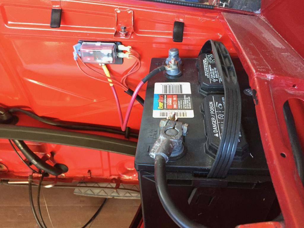
Trying to clean up this mess of wires to the positive battery connector. Anybody know why all of these red wires are here and what they do? I would like something cleaner and with a stock look.
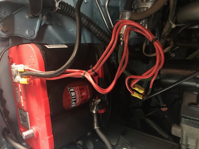 Also got this original connector from @bdstone914 and have no idea how that would figure into an original set up. Anybody know? 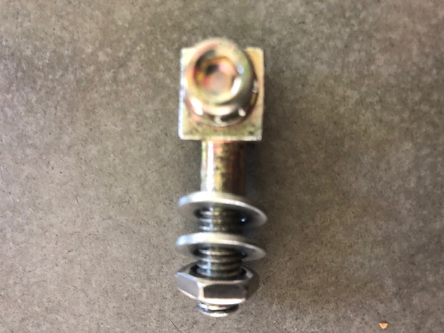 |
   |

 
|
| pvollma |
May 15 2020, 05:36 PM
Post
#2
|
|
Member Group: Members Posts: 205 Joined: 12-May 13 From: Camp Hill, PA Member No.: 15,862 Region Association: MidAtlantic Region |
QUOTE(914_7T3 @ May 15 2020, 07:05 PM)  Trying to clean up this mess of wires to the positive battery connector. Anybody know why all of these red wires are here and what they do? I would like something cleaner and with a stock look. One problem sometimes talked about is the lack of fuses for those wires. One solution is to run them through a fuse block as I did. I got the fuse block from a marine supply store online, it's rated as water-resistant rather than waterproof, but I still run with my rain tray, so that's all I need. Obviously, this would not retain the "stock look" but rather the preferred "not on fire look." 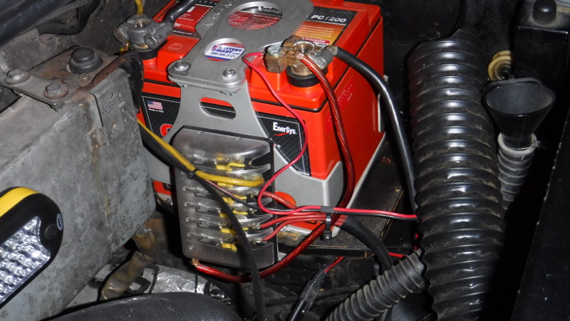 |
|
|
|
| mepstein |
May 15 2020, 05:39 PM
Post
#3
|
|
914-6 GT in waiting Group: Members Posts: 19,271 Joined: 19-September 09 From: Landenberg, PA/Wilmington, DE Member No.: 10,825 Region Association: MidAtlantic Region |
QUOTE(914_7T3 @ May 15 2020, 07:05 PM) Trying to clean up this mess of wires to the positive battery connector. Anybody know why all of these red wires are here and what they do? I would like something cleaner and with a stock look. Also got this original connector from @bdstone914 and have no idea how that would figure into an original set up. Anybody know? Attached image(s) 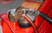
|
|
|
|
| tygaboy |
May 15 2020, 05:55 PM
Post
#4
|
|
914 Guru Group: Members Posts: 5,292 Joined: 6-October 15 From: Petaluma, CA Member No.: 19,241 Region Association: Northern California |
Just be sure that any electronics that want a totally clean 12V get mounted DIRECTLY to the + post, not to a power block. This to damp any voltage spikes that might otherwise damage the component.
|
|
|
|
| bbrock |
May 16 2020, 10:05 AM
Post
#5
|
|
914 Guru Group: Members Posts: 5,269 Joined: 17-February 17 From: Montana Member No.: 20,845 Region Association: Rocky Mountains |
To try to answer your original questions, below is a pic of mine to give an idea. Right now I have only a terminal connected for testing electrical so the big fat wire going to the starter is missing. Also ignore the wire and connection in the foreground. That is for a battery tender. Also, on the back side you can just barely see a little bit of a big fat wire that is for my stereo amp which is obviously not original.
What is left are four wires that are bundled into two pairs that terminate. One pair of wires routes through the firewall and up the tunnel. The other routes over to the relay board. One of the wires running to the relay was originally 2.5mm (13 gauge) and the rest were originally 4.0mm(11gauge). The two ring connectors connect to your little mystery connector. The large bolt on that connector replaces the through bolt on your lead battery terminal. Then the ring connectors attach with the allen head bolt. Thanks for showing me that is supposed to be allen head BTW, now I have something else to change (IMG:style_emoticons/default/biggrin.gif) Hey, if you get a chance, could you snap a pic of the hole in that connector with the allen bolt removed? I have the 914Rubber repro of that block and just curious what the original looks like inside. Looks like yours is wired right but somebody has spliced in larger wires with crimp butt connectors. 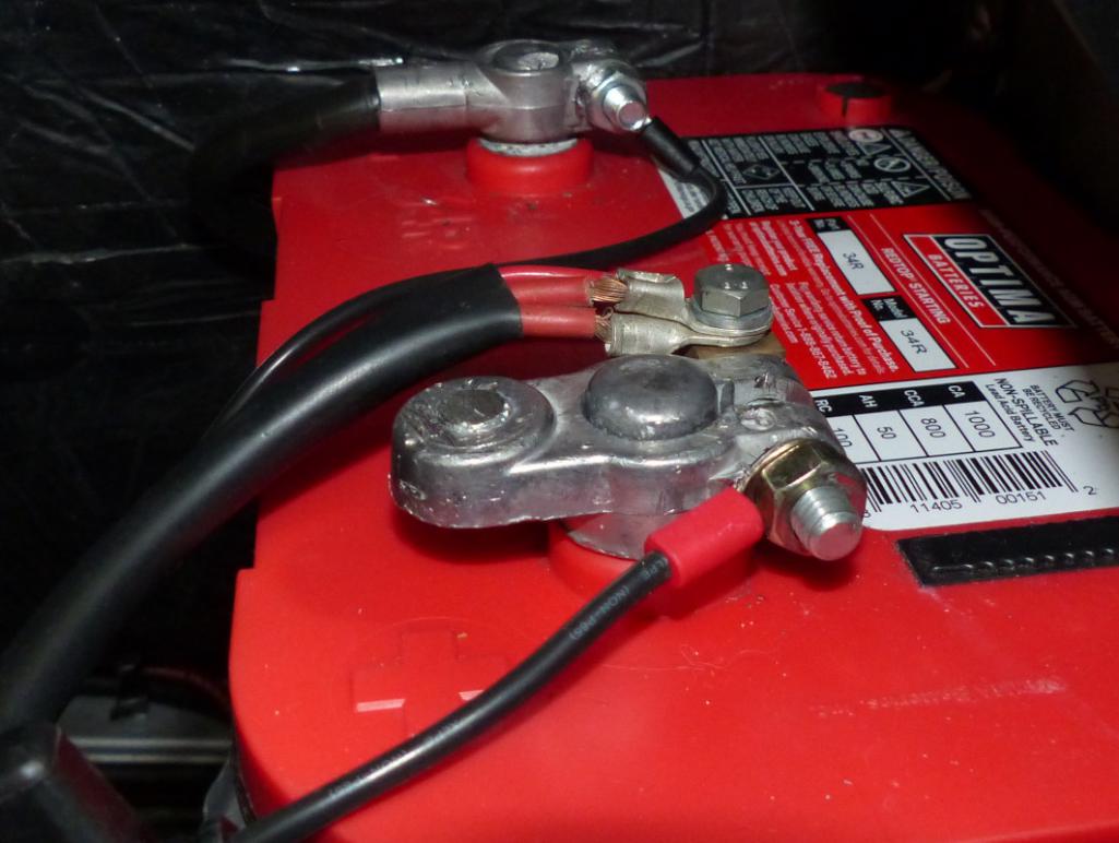 |
|
|
|
| windforfun |
May 16 2020, 10:39 AM
Post
#6
|
|
Senior Member Group: Members Posts: 1,785 Joined: 17-December 07 From: Blackhawk, CA Member No.: 8,476 Region Association: None |
Here's mine. There's a connector for the battery tender. All audio components get attached directly to the battery. A Pi filter can also be used to suppress alternator noise.
Attached thumbnail(s) 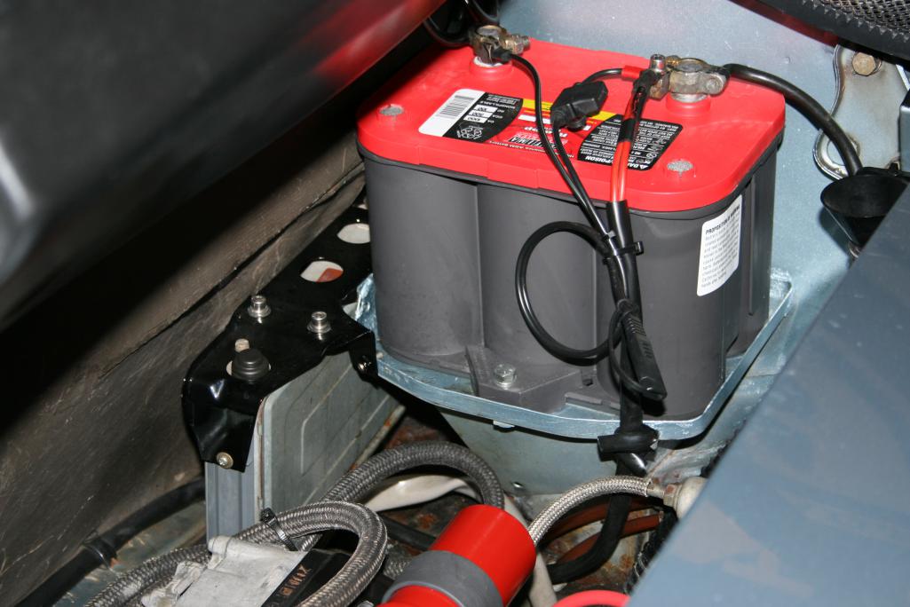
|
|
|
|
| FlacaProductions |
May 16 2020, 11:23 AM
Post
#7
|
|
Senior Member Group: Members Posts: 1,584 Joined: 24-November 17 From: LA Member No.: 21,628 Region Association: Southern California |
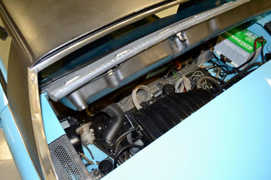
here's mine - 4 wires in 2 bundles of 2 to the thru-bolt connector on the + post. Although, my battery has the posts in the "wrong" position and is flipped.
 |
|
|
|
| 914_7T3 |
May 16 2020, 11:50 AM
Post
#8
|
|
Please forgive me, I'm new to all of this! Group: Members Posts: 1,853 Joined: 3-April 17 From: Los Angeles, CA Member No.: 20,991 Region Association: Southern California |
QUOTE(bbrock @ May 16 2020, 09:05 AM) To try to answer your original questions, below is a pic of mine to give an idea. Right now I have only a terminal connected for testing electrical so the big fat wire going to the starter is missing. Also ignore the wire and connection in the foreground. That is for a battery tender. Also, on the back side you can just barely see a little bit of a big fat wire that is for my stereo amp which is obviously not original. What is left are four wires that are bundled into two pairs that terminate. One pair of wires routes through the firewall and up the tunnel. The other routes over to the relay board. One of the wires running to the relay was originally 2.5mm (13 gauge) and the rest were originally 4.0mm(11gauge). The two ring connectors connect to your little mystery connector. The large bolt on that connector replaces the through bolt on your lead battery terminal. Then the ring connectors attach with the allen head bolt. Thanks for showing me that is supposed to be allen head BTW, now I have something else to change (IMG:style_emoticons/default/biggrin.gif) Hey, if you get a chance, could you snap a pic of the hole in that connector with the allen bolt removed? I have the 914Rubber repro of that block and just curious what the original looks like inside. Looks like yours is wired right but somebody has spliced in larger wires with crimp butt connectors. Ok, that makses sense now. So *(I) should splice in the correct gauge wiring and shield it. Then get them to terminate onto two rings (2 per) to the connector. *not me personally of course as I already arced a wrench getting the battery on in the first place (IMG:style_emoticons/default/laugh.gif) Here are the photos you requested. Its just a regular threaded hole, nothing special. 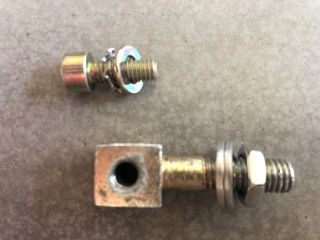 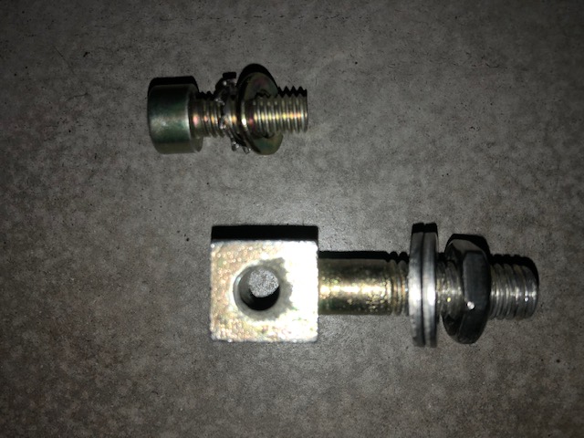 |
|
|
|
| Frankvw |
May 16 2020, 12:02 PM
Post
#9
|
|
working on my first 914 ! Group: Members Posts: 651 Joined: 13-April 16 From: Holland, the Netherlands Member No.: 19,896 Region Association: Europe |
great you have an original bolt like that !
914rubber created them a while ago to replace them, since they are hard to find https://900designs-container.zoeysite.com/b...tive-terminal-1 |
|
|
|
| FlacaProductions |
May 16 2020, 12:04 PM
Post
#10
|
|
Senior Member Group: Members Posts: 1,584 Joined: 24-November 17 From: LA Member No.: 21,628 Region Association: Southern California |
I'm not going to go against what Bruce says but I'm not entirely sure that OEM is an allen head....
|
|
|
|
| bbrock |
May 16 2020, 12:40 PM
Post
#11
|
|
914 Guru Group: Members Posts: 5,269 Joined: 17-February 17 From: Montana Member No.: 20,845 Region Association: Rocky Mountains |
QUOTE(FlacaProductions @ May 16 2020, 12:04 PM) I'm not going to go against what Bruce says but I'm not entirely sure that OEM is an allen head.... I'm not either. If the allen head has KAMAX stamped on it, I'll be convinced. Thanks for the pics Jeffrey (IMG:style_emoticons/default/beerchug.gif) The 914Rubber repro has a problem. They threaded the large stud through the bottom such that it threads across the bore for the small terminal bolt. The small bolt they supply is too long to clamp down tight with the large bolt in place because it bottoms out on the large bolt. You either need to use a shorter small bolt and be satisfied with fewer threads engaged, or cut or back out the large stud with fewer threads engaged. I've thought about cutting the stud and welding it to the block so it doesn't pull out, but with my skill, I'd probably screw it all up. There was another thread on this maybe a year ago. |
|
|
|
| bbrock |
May 16 2020, 12:48 PM
Post
#12
|
|
914 Guru Group: Members Posts: 5,269 Joined: 17-February 17 From: Montana Member No.: 20,845 Region Association: Rocky Mountains |
QUOTE(914_7T3 @ May 16 2020, 11:50 AM) Ok, that makses sense now. So *(I) should splice in the correct gauge wiring and shield it. Then get them to terminate onto two rings (2 per) to the connector. *not me personally of course as I already arced a wrench getting the battery on in the first place (IMG:style_emoticons/default/laugh.gif) A couple thoughts. It looks like your wires are spliced with crimped butt connectors. I'm not a fan, but there is little down side to having those wires larger than spec other than appearance. Once you put sheathing over them, it would be hard to tell. Finding metric wire can be difficult and substituting easily found 10 and 12 gauge wire won't be noticeable. Just make sure they use GXLwire. I know you are like me and will want close to the correct gauge but just tossing out that going oversize like you seem to have there isn't a problem as long as the splices are good. |
|
|
|
| FlacaProductions |
May 16 2020, 02:04 PM
Post
#13
|
|
Senior Member Group: Members Posts: 1,584 Joined: 24-November 17 From: LA Member No.: 21,628 Region Association: Southern California |
I just learned something here - GXL wire - noted...and it makes sense.
|
|
|
|
| barefoot |
May 16 2020, 02:18 PM
Post
#14
|
|
Senior Member Group: Members Posts: 1,273 Joined: 19-March 13 From: Charleston SC Member No.: 15,673 Region Association: South East States |
I added a 1 in 4 out fuze box to insure no circuits were un-protected when i was installing a new to me harness.
 |
|
|
|
| 914_7T3 |
May 18 2020, 12:09 PM
Post
#15
|
|
Please forgive me, I'm new to all of this! Group: Members Posts: 1,853 Joined: 3-April 17 From: Los Angeles, CA Member No.: 20,991 Region Association: Southern California |
Thanks all for your responses and good call on the GXL. Glad I asked and now have a path forward.
(IMG:style_emoticons/default/beerchug.gif) |
|
|
|
| bbrock |
May 18 2020, 03:15 PM
Post
#16
|
|
914 Guru Group: Members Posts: 5,269 Joined: 17-February 17 From: Montana Member No.: 20,845 Region Association: Rocky Mountains |
QUOTE(914_7T3 @ May 18 2020, 12:09 PM) Thanks all for your responses and good call on the GXL. Glad I asked and now have a path forward. (IMG:style_emoticons/default/beerchug.gif) FYI, you can also use TXL which is thin-walled so less overall diameter but pretty much the same performance specs as GXL. But TXL will look skinnier than factory for a given gauge. I used it when I ran a wire through the harness up front for the fuel pump. The factory increased the size of that wire after the pump was officially relocated to the front and the TXL let me add a pretty big wire without bloating the bundle. BTW, I knew NONE of this before working through the rat's nest of a harness I pulled out of my car. (IMG:style_emoticons/default/rolleyes.gif) |
|
|
|
| porschetub |
May 18 2020, 06:04 PM
Post
#17
|
|
Advanced Member Group: Members Posts: 4,698 Joined: 25-July 15 From: New Zealand Member No.: 18,995 Region Association: None |
QUOTE(bbrock @ May 17 2020, 06:48 AM) QUOTE(914_7T3 @ May 16 2020, 11:50 AM) Ok, that makses sense now. So *(I) should splice in the correct gauge wiring and shield it. Then get them to terminate onto two rings (2 per) to the connector. *not me personally of course as I already arced a wrench getting the battery on in the first place (IMG:style_emoticons/default/laugh.gif) A couple thoughts. It looks like your wires are spliced with crimped butt connectors. I'm not a fan, but there is little down side to having those wires larger than spec other than appearance. Once you put sheathing over them, it would be hard to tell. Finding metric wire can be difficult and substituting easily found 10 and 12 gauge wire won't be noticeable. Just make sure they use GXLwire. I know you are like me and will want close to the correct gauge but just tossing out that going oversize like you seem to have there isn't a problem as long as the splices are good. (IMG:style_emoticons/default/agree.gif) strange to see those wires are extended like that and not really in a good way ,check them and see if they are too short ?. Yes bbrock wire and connector sizes are odd, found that out. |
|
|
|
| 914_7T3 |
May 18 2020, 06:43 PM
Post
#18
|
|
Please forgive me, I'm new to all of this! Group: Members Posts: 1,853 Joined: 3-April 17 From: Los Angeles, CA Member No.: 20,991 Region Association: Southern California |
OCD now kicking in....... I think there is enough original cable to do away with the extended red wire clustrf*#ck altogether and just connect direct to the battery connector.
Problem is the 34R still doesn't clear the rain tray so I think I'm going to pull it and set it aside for my type 1. Researching now, but may have a couple of options for shorter AGM batteries in original size 42 or even 96R with positive terminals on the right. Details to follow..... I know, I'm sick (IMG:style_emoticons/default/screwy.gif) |
|
|
|
| bbrock |
May 18 2020, 06:56 PM
Post
#19
|
|
914 Guru Group: Members Posts: 5,269 Joined: 17-February 17 From: Montana Member No.: 20,845 Region Association: Rocky Mountains |
QUOTE(914_7T3 @ May 18 2020, 06:43 PM) OCD now kicking in....... I think there is enough original cable to do away with the extended red wire clustrf*#ck altogether and just connect direct to the battery connector. Problem is the 34R still doesn't clear the rain tray so I think I'm going to pull it and set it aside for my type 1. Researching now, but may have a couple of options for shorter AGM batteries in original size 42 or even 96R with positive terminals on the right. Details to follow..... I know, I'm sick (IMG:style_emoticons/default/screwy.gif) (IMG:style_emoticons/default/popcorn[1].gif) (IMG:style_emoticons/default/popcorn[1].gif) Looking forward to seeing what you found. That said, my Optima 34R clears the rain tray (barely) or can be flipped around with the terminals at the quarter panel with enough cable to connect. Strange that yours isn't clearing. |
|
|
|
| 914_7T3 |
May 18 2020, 07:04 PM
Post
#20
|
|
Please forgive me, I'm new to all of this! Group: Members Posts: 1,853 Joined: 3-April 17 From: Los Angeles, CA Member No.: 20,991 Region Association: Southern California |
QUOTE(bbrock @ May 18 2020, 05:56 PM) QUOTE(914_7T3 @ May 18 2020, 06:43 PM) OCD now kicking in....... I think there is enough original cable to do away with the extended red wire clustrf*#ck altogether and just connect direct to the battery connector. Problem is the 34R still doesn't clear the rain tray so I think I'm going to pull it and set it aside for my type 1. Researching now, but may have a couple of options for shorter AGM batteries in original size 42 or even 96R with positive terminals on the right. Details to follow..... I know, I'm sick (IMG:style_emoticons/default/screwy.gif) (IMG:style_emoticons/default/popcorn[1].gif) (IMG:style_emoticons/default/popcorn[1].gif) Looking forward to seeing what you found. That said, my Optima 34R clears the rain tray (barely) or can be flipped around with the terminals at the quarter panel with enough cable to connect. Strange that yours isn't clearing. There will not be enough of the original cable to flip it the other way. It won't clear the rain tray for whatever reason so now looking at a battery that contains the posts within the 6 7/8" clearance that is there or I need an original battery terminal clamp or both. 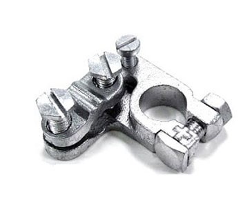 |
|
|
|
|
1 User(s) are reading this topic (1 Guests and 0 Anonymous Users)
0 Members:

|
Lo-Fi Version | Time is now: 16th May 2024 - 01:28 AM |
Invision Power Board
v9.1.4 © 2024 IPS, Inc.