|
|
|
Porsche, and the Porsche crest are registered trademarks of Dr. Ing. h.c. F. Porsche AG.
This site is not affiliated with Porsche in any way. Its only purpose is to provide an online forum for car enthusiasts. All other trademarks are property of their respective owners. |
|
|

  |

| CBee |
 Jul 1 2020, 12:10 PM Jul 1 2020, 12:10 PM
Post
#21
|
|
G Force Junkie  Group: Members Posts: 23 Joined: 17-June 18 From: AVL,NC Member No.: 22,232 Region Association: South East States |
Yeah! Super fab skills.
I'll be borrowing some of your ideas on my build as I have floor, firewall, and pedal area issues on my car and will going Subaru on the engine and gearbox too. Very nice work. Clark |
   |

 
|
| waltonsm |
Jul 3 2020, 11:53 AM
Post
#22
|
|
Member Group: Members Posts: 93 Joined: 27-June 14 From: United States Member No.: 17,561 Region Association: Pacific Northwest |
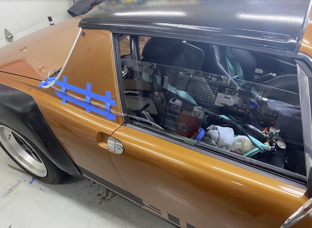
QUOTE(Thunderchief @ Jun 30 2020, 11:57 PM)  What kind of heated seats are you running? Do they sit higher than stock? The seats are leather/alcantara out of a BRZ. I got them for $500 on ebay after selling my 914 seats that had been recovered for a bit more. So far I have changed the mount points for the seat (although the way they showed up would have probably been better for me in the end), I removed the airbags, and have used some clamps and vicegrips to widen the bolstering frames on the driver seat. I have aftermarket lumbar adjust bags that I haven't installed yet. 4 hr roadtrips are not a problem for us, but seats are pretty personal things. My wife is pretty happy with the passenger seat width. Note that I redid the entire rear floor and this enabled me to get the rear mount points basically on the floor skin. In the end he height might be 1/2" or so higher. The biggest impact is the thickness of the seatback. This results in the total legroom being decreased by at least 2-3 inches. This works for us at 5'8"/5'6". My 6'4" friend fits* and enjoys it, but we aren't going anywere with the top on, or for more than an hour or so. Heated seats are necessary... i drive it down below 50 deg with a little down throw blanket :) Plan to finish the heater core install this summer, along with the planning for the AC core. The tunnel has the fittings for the AC hoses, and I plan to mount the core near the oil cooler on subframe, but I realized I need to have this system such that I can easily remove the AC pump and hoses from the engine when i drop it without the need to recharge the system. Steve |
|
|
|
| waltonsm |
Jul 3 2020, 12:38 PM
Post
#23
|
|
Member Group: Members Posts: 93 Joined: 27-June 14 From: United States Member No.: 17,561 Region Association: Pacific Northwest |
QUOTE(Chris H. @ Jul 1 2020, 08:05 AM) Wow REALLY cool build! Thanks for sharing it. Some great new ideas in there. Among many other things, I really like how you did the center tunnel. Might have to borrow that one. Question...so your ONLY radiator air exit vents are in the former headlight buckets? Curious to hear how that works since no one has done it before. Any cooling issues at all so far? yes the only radiator vents are through the former headlight buckets. You can see from these pictures how i sealed everything up to duct air out of the headlight buckets. This can be a low pressure zone depending on what is happening right at the bumper. So i went forward knowing I can trip the flow right before the bucket, and open up the bumper and reinforce to get more frontal area on the radiator. 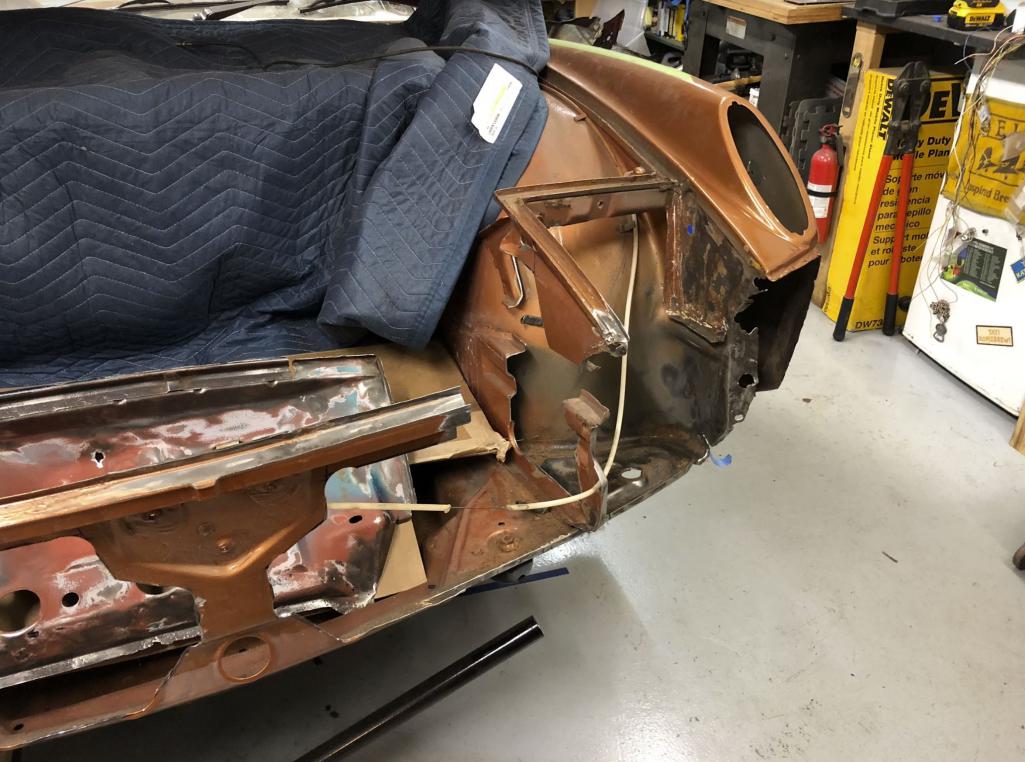 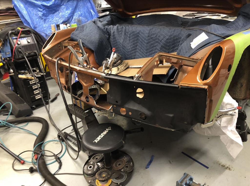 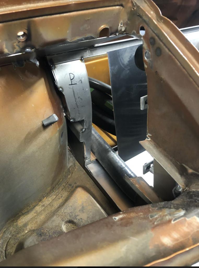 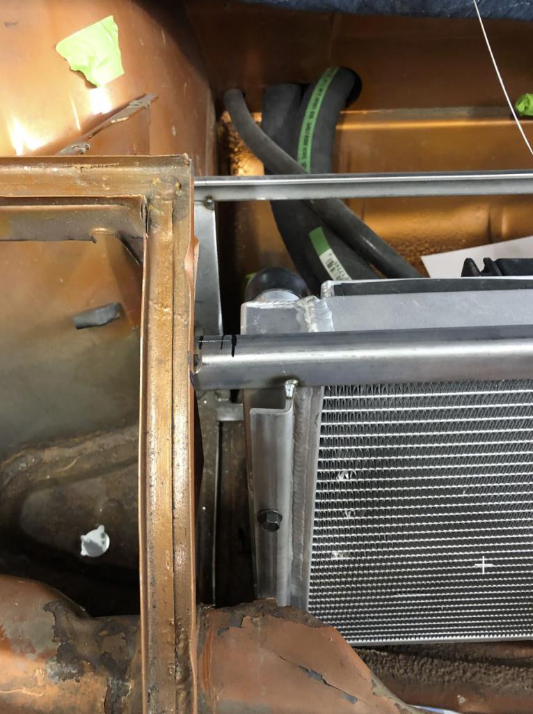 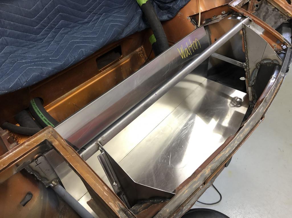 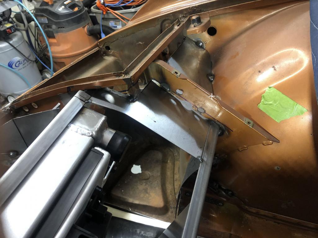 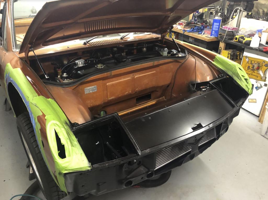 I took it to the track in this config. no headlight buckets, no lower valences, no rocker panels. 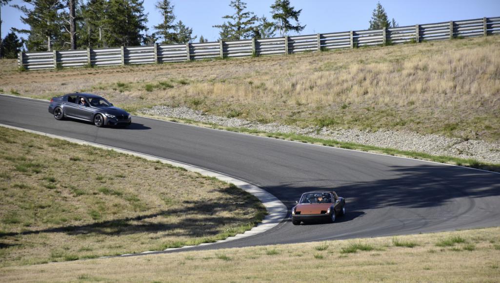 I have a thermostat for the oil cooler on the subrame, but the car barely hit 200F on the track in this configuration with 20 min stints at the Ridge. Also, driving 6/10 on first day out (to balance tire pressures, brake bias, sway bars etc. am i in the ballpark.. I was happy with it. In this configuration, I never even got to 185F on the freeway, mostly around 165. so too cold. and I could continue with plan for headlight vents. and splitter. Glen provided some inspiration for the splitter here when I was trying to figure out how to make an RSR style airdam that would function as a splitter too. 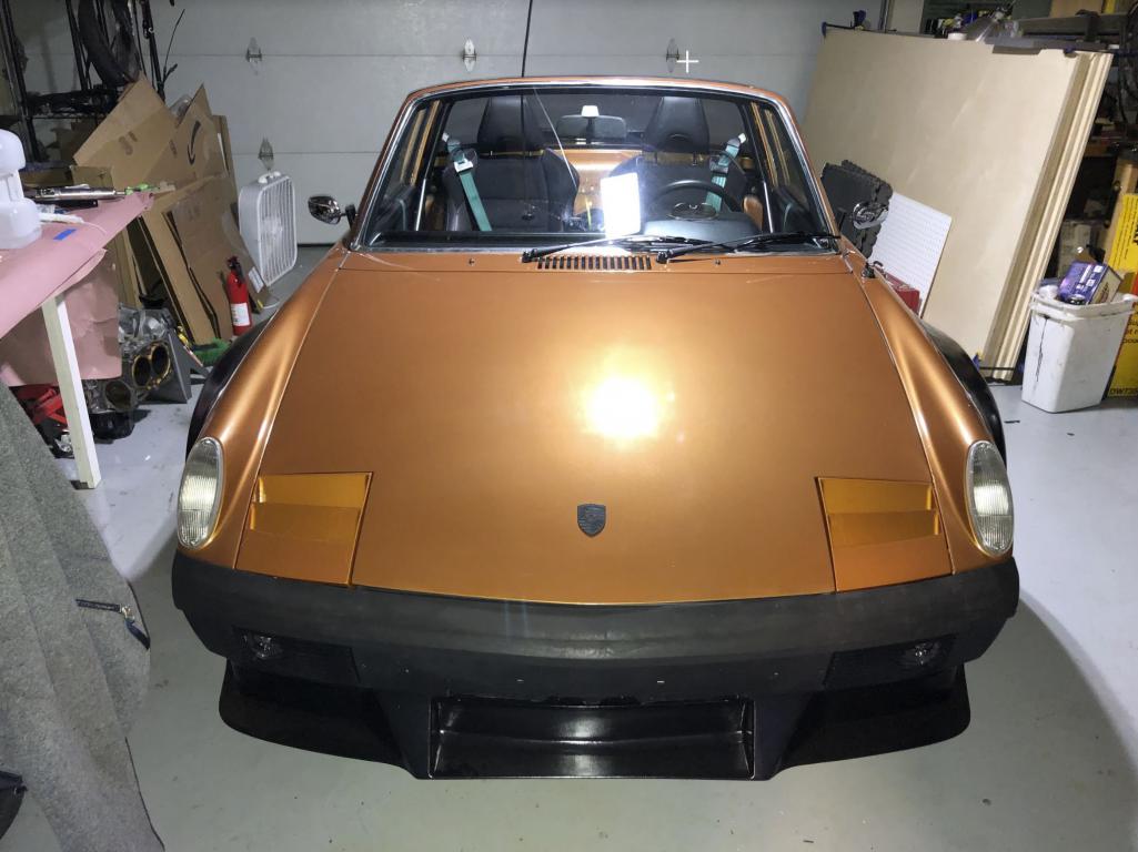 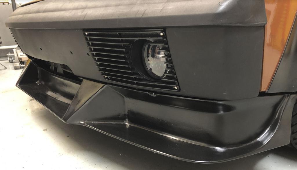 You can see from this configuration that I have lot more area I can open up on the bumper to increase radiator frontal area. I also can seal it better between bumper and chassis if I need to. I also can trip the flow before the headlight buckets vent louvre things if needed. The subaru fans are set at 185 and 205 I think. Sitting on the freeway in traffic on a hot day, I will hit 205 now and sit there. As soon as I start moving it drops down to 185. On a 50 deg day on the freeway it is below 185 still. I haven't had it on the track in this configuration, but this is in the ballpark and will work with minor tuning. Steve |
|
|
|
| waltonsm |
Jul 3 2020, 12:51 PM
Post
#24
|
|
Member Group: Members Posts: 93 Joined: 27-June 14 From: United States Member No.: 17,561 Region Association: Pacific Northwest |
QUOTE(DRPHIL914 @ Jul 1 2020, 08:31 AM) QUOTE(Thunderchief @ Jun 13 2020, 02:18 AM) Super cool! Very clean and professional looking. Good job. first comment is : WOW!! nice job! of course I am partial to the color being a L99k owner myself. its not easy to get seats like that in a 914 those look super comfortable!, only thing I would pick at , not my taste is the fenders, but that's just because there is nothing else to pick on.. but really maybe some factory GT fenders at some point to really clean it up but, this may be my favorite suby build yet. Partly the color, but mostly because you really did everything yourself and at such a high level too, I cant imagine how much fun it is to drive a 350hp 914!!! well done sir! Phil Thanks Phil! It certainly is more than a handful. I may put an M3 standalone traction control system in this winter. But that will require additional brake lines. Not a deal breaker by any means, but annoying for sure. I went on a hunt for viper green or copper. This is the one I found that I could only put screwdrivers through the floor on.. with a plan to cut. The fenders... I went back and forth, a LOT! I decided I wanted to do this style because it is so obviously far from stock. I do plan to paint these fenders copper as well, but I have more composite work to do before getting stuff painted. some of it might be a bit controversial too. It took me an absurd amount of time in glasswork and fairing to get the fender edges right from every angle. And then I wanted to have no fasteners... When you have a sharp edge like that it it is much more difficult than with fairing in a smooth radius. maybe there is a lesson there, steel would have probably been less time honestly. I have a giant carbon fiber wing I have built (which is the rear bicycle and surfboard rack point. I have made fork mounts that are installed in the factory targa bar points already. I haven't decided on wing mounting, and I wont do it until I am happy with it, but I need/want the downforce and roof rack. I also have mocked up many different iterations of 904/GT40 style B pillar scoops for the intercooler and intake. I also haven't pulled the trigger on this yet, but probably will have both of these done before winter. So maybe next year the fenders will be L99K. Steve |
|
|
|
| waltonsm |
Jul 3 2020, 12:56 PM
Post
#25
|
|
Member Group: Members Posts: 93 Joined: 27-June 14 From: United States Member No.: 17,561 Region Association: Pacific Northwest |
QUOTE(CBee @ Jul 1 2020, 11:10 AM) Yeah! Super fab skills. I'll be borrowing some of your ideas on my build as I have floor, firewall, and pedal area issues on my car and will going Subaru on the engine and gearbox too. Very nice work. Clark Let me know if you specific pictures at any point. I have lots. I am super happy with the tilton 600 dual MC setup. It is isn't cheap, but everything is tunable for this sort of nonsense, so it is easier, and possibly cheaper in the long run to dial it in. Steve |
|
|
|
| waltonsm |
Jun 16 2021, 09:33 PM
Post
#26
|
|
Member Group: Members Posts: 93 Joined: 27-June 14 From: United States Member No.: 17,561 Region Association: Pacific Northwest |
Nearly a year has passed since my last updates. Turns out I did lot more than work on the car over the winter, but lots of progress was made. I will start dumping photos and descriptions of the process. In summary, due to turbo/manifold/intercooler, tuning, and downforce/wing, it is now a very driveable, 450 hp, 914.
 |
|
|
|
| waltonsm |
Jun 16 2021, 09:53 PM
Post
#27
|
|
Member Group: Members Posts: 93 Joined: 27-June 14 From: United States Member No.: 17,561 Region Association: Pacific Northwest |
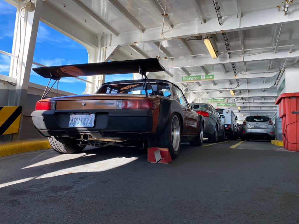
For a long time I had plans to build the wing. I knew I needed the downforce with the planned torque, and also the desire to carry boards, bikes, and maybe our kayaks. I have been custom roof racks or boxes for most of our cars.
I got distracted by making an even larger version of this for our 3.6 VR6 corrado racecar, but planned to use those lessons for improved aesthetics. My goal was to make a big wing with a modern airfoil, designed around the speeds I want downforce, and I want adjustability, and potential the opportunity for tunable, passive AOA adjustment in the future. It is fixed for now, but have the adjustment if I get really bored in the future. I had cores hot wire cut, installed a spar, and did a low vacuum operation by throttling a cheap vacuum pump I got to install some heat pumps. 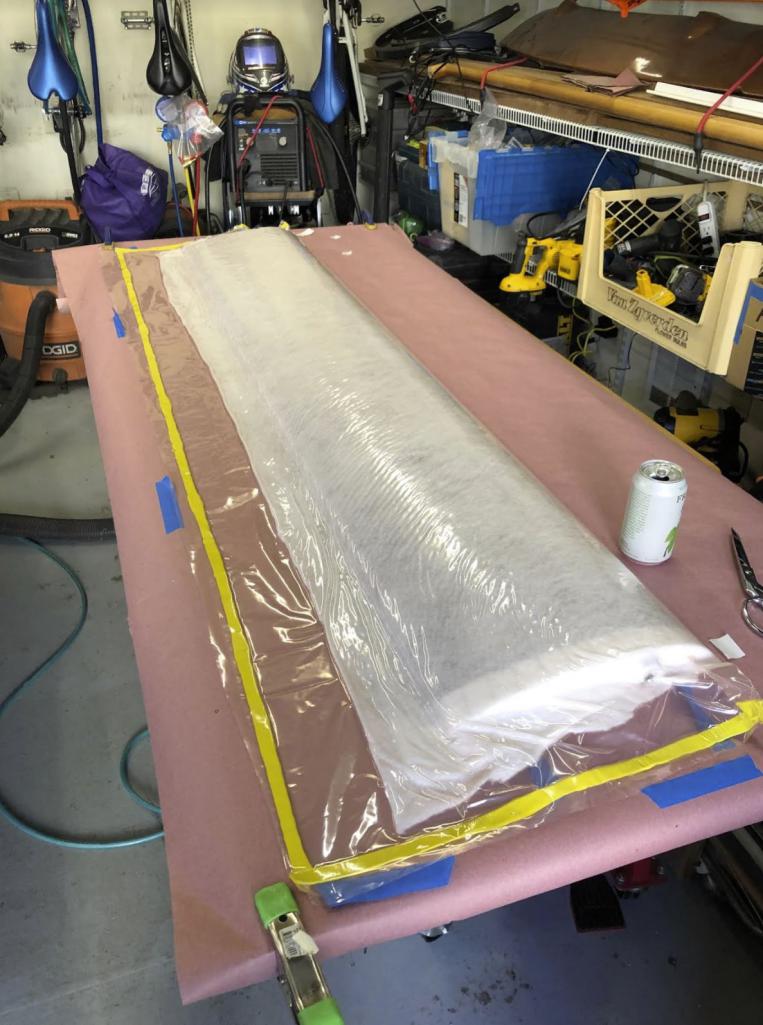 After the wing was build I spent 6 months deciding how I was going to mount it, but mostly, where. 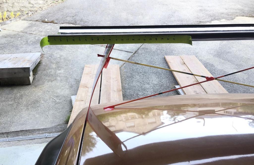 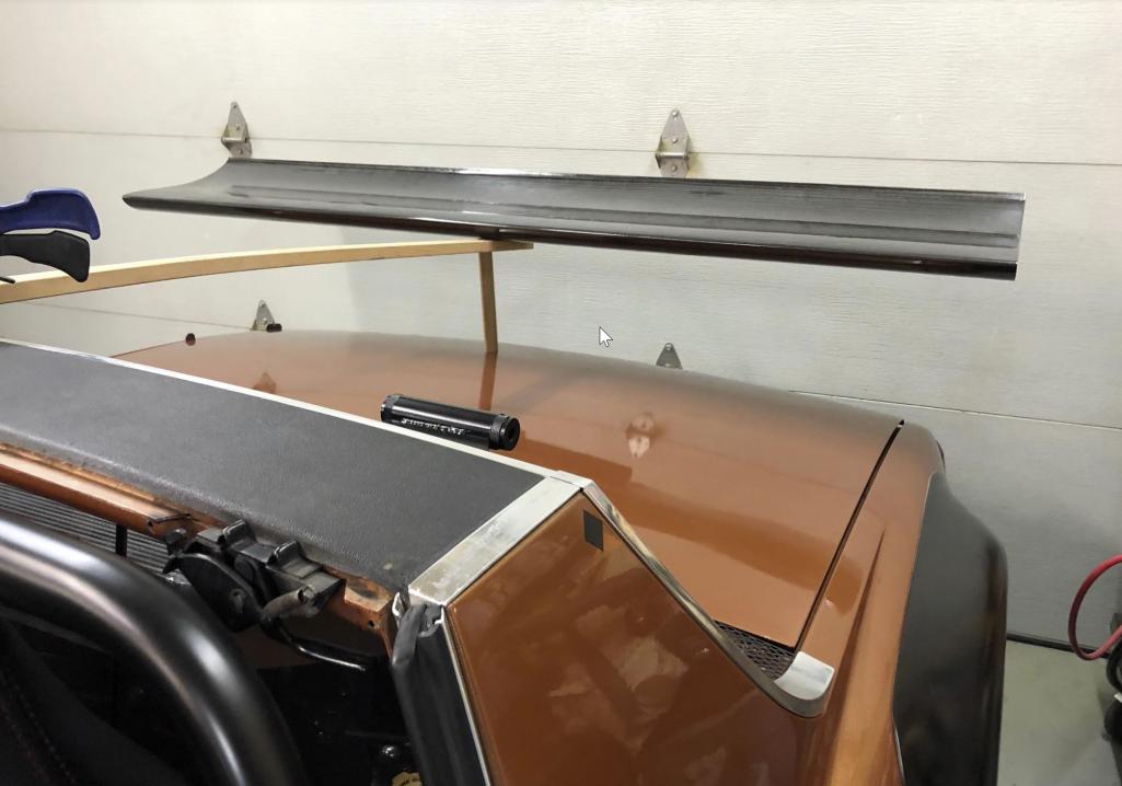 Attached thumbnail(s) 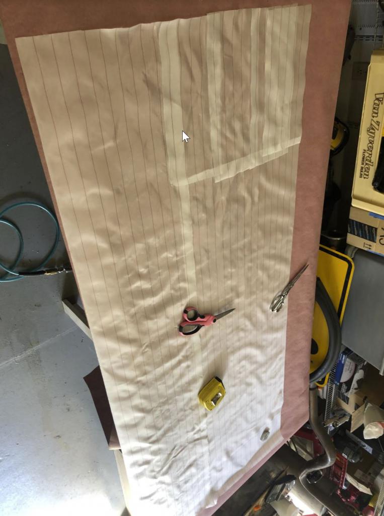
|
|
|
|
| waltonsm |
Jun 16 2021, 10:07 PM
Post
#28
|
|
Member Group: Members Posts: 93 Joined: 27-June 14 From: United States Member No.: 17,561 Region Association: Pacific Northwest |
After a few more months I decided I wanted the wing to float and be as separate from the lines of the 914 as possible. But also match where possible. To keep it light looking, endplates are out, it needs to be black, and the support structure should not be offensive, but shouldn't grab attention.
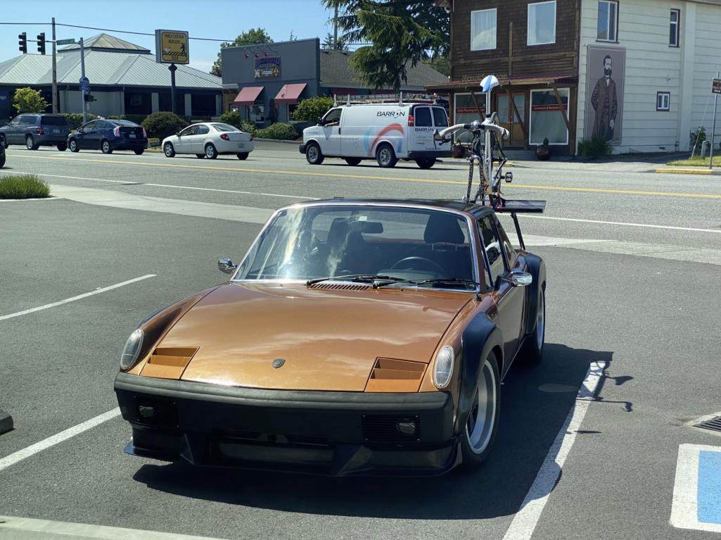
I decided to follow and approximation of the A pillar to B pillar roofline, and also taper it inward toward the top to follow the progression of the A to B pillar, and also make the tube triangulation tilt forward like the sail panel. Angle of attack is adjustable from roughly 0-15 degrees, but I use it in the 6-10 region I think, I built the foil with a 1/4 gurney flap mostly to toughen the trailing edge. Its a S1223 RTL foil. Lots of data out there on this one. I had a wing mount design that avoided fasteners through the rear deck, but it seemed to dicey in the end, especially in any sort of collision. In the end I just added the fasteners and added peace of mind and further fab complication. 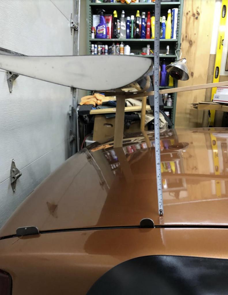 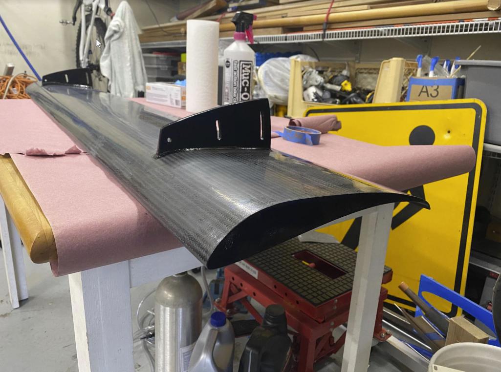 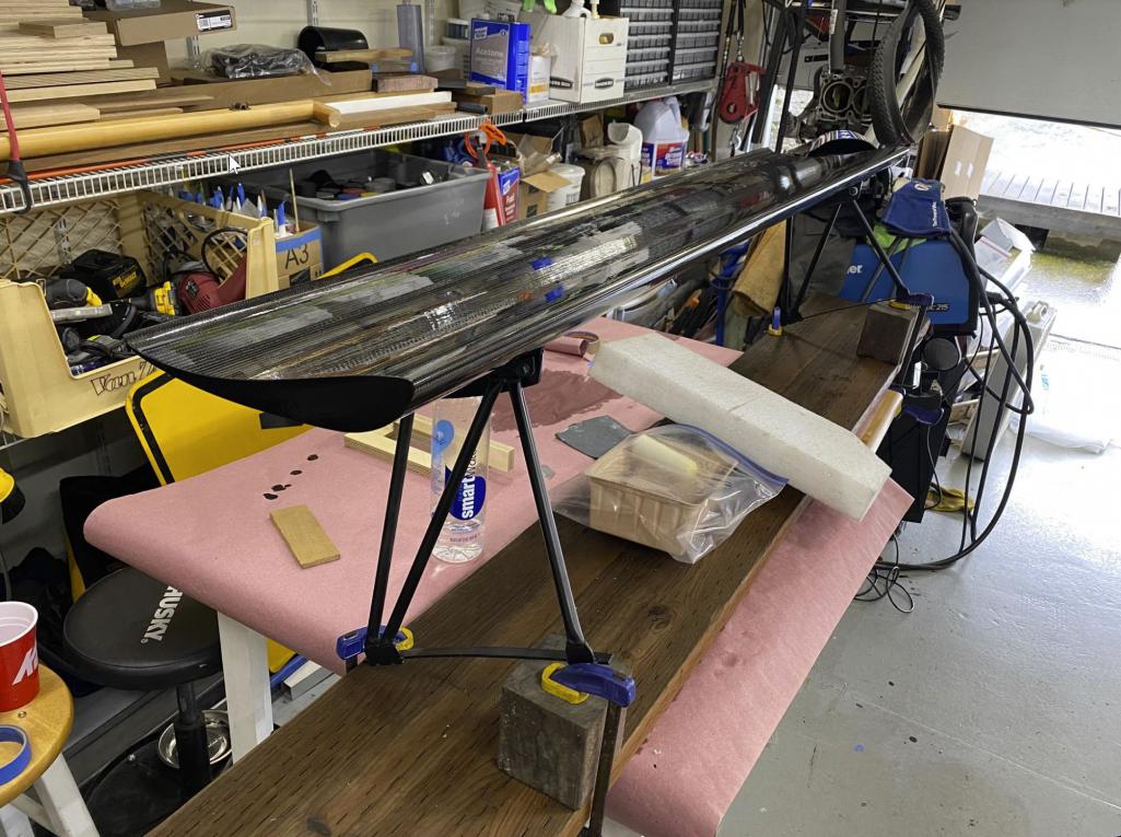  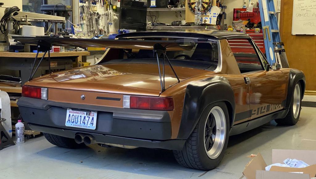 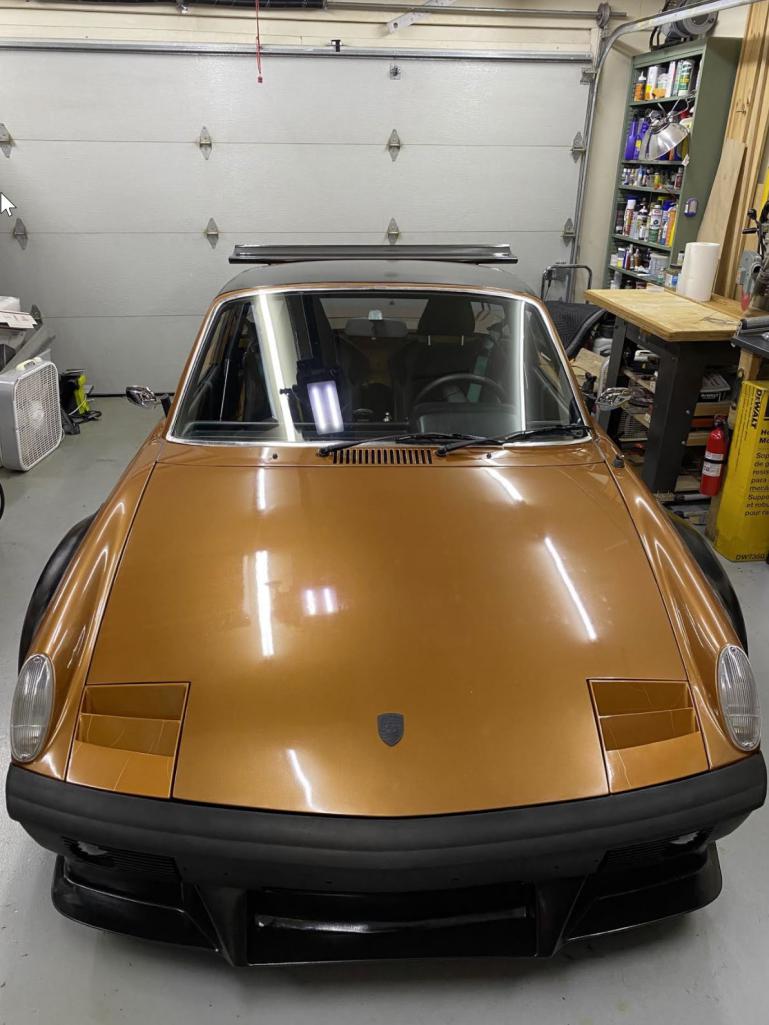 And most importantly. It conforms to standard bar height, and passed functional testing. 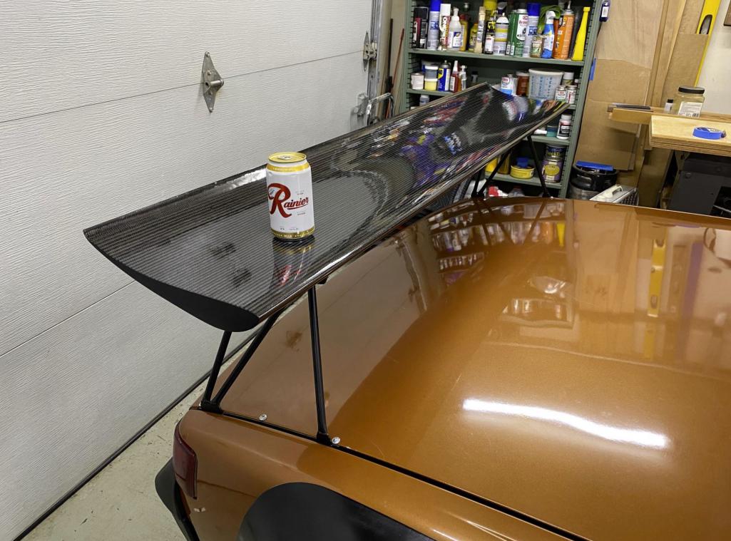 |
|
|
|
| mgarrison |
Jun 17 2021, 09:18 AM
Post
#29
|
|
Member Group: Members Posts: 416 Joined: 14-February 20 From: Chandler, AZ Member No.: 23,922 Region Association: Southwest Region |
Amazing Suby build! Incredible fab skills... (IMG:style_emoticons/default/pray.gif)
Any additional details & pics you can share on radiator plumbing & pump. Any details on the Tilton pedal cluster install would be appreciated too. I'm early in the process of my Suby conversion. Looking to use a WRX engine & trans as well. |
|
|
|
| AZBanks |
Jun 17 2021, 09:23 AM
Post
#30
|
|
Senior Member Group: Members Posts: 1,079 Joined: 7-December 05 From: New River, AZ Member No.: 5,245 Region Association: Southwest Region |
Amazing build. I'm curious what metalworking tools you use, brakes, tube benders, etc.
|
|
|
|
| ValcoOscar |
Jun 17 2021, 09:41 AM
Post
#31
|
|
Garage Life Group: Members Posts: 2,652 Joined: 19-November 13 From: SoCal Member No.: 16,669 Region Association: Southern California |
(IMG:style_emoticons/default/biggrin.gif) (IMG:style_emoticons/default/smile.gif)
(IMG:style_emoticons/default/beerchug.gif) (IMG:style_emoticons/default/beer.gif) (IMG:style_emoticons/default/beer3.gif) (IMG:style_emoticons/default/first.gif) O N E S E X Y 9 1 4 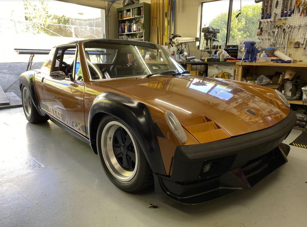 Nice build Congrats!!!! O |
|
|
|
| waltonsm |
Jun 21 2021, 08:06 PM
Post
#32
|
|
Member Group: Members Posts: 93 Joined: 27-June 14 From: United States Member No.: 17,561 Region Association: Pacific Northwest |
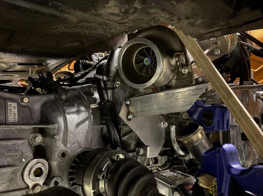
QUOTE(AZBanks @ Jun 17 2021, 08:23 AM) Amazing build. I'm curious what metalworking tools you use, brakes, tube benders, etc. I don't have many sophisticated tools. I did borrow a friends hydraulic bender for the cage and rear subframe. The bender was a vertical bender than makes it easy to use a digital magnetic angle finder to make very repeatable angles. Other than that, 95% of what I do is plan cuts out of various stock tube shapes I got for scrap prices. I got a bunch of 1-6' sticks of different profiles and wall thicknesses, and then I dig through the pile, find the closest one, mark them out with cardboard templates, and cut it down to size. I almost exclusively use a cutoff wheel and flap disc for the work. As a note my favorite materials for templates are cardboard beer boxes and cotton resume paper. The resume paper works great because it doesn't stretch much, but does stretch just enough to not tear while you do a rubbing of the surface with dirty fingers. This transfers the pattern really well, especially when you can't easily see where you are working. For example, the long repair was cut out of 2x6" rectangular tube that had a matching radius on it, I generally cut out the weld on formed and welded tube if I can keep it as open section. 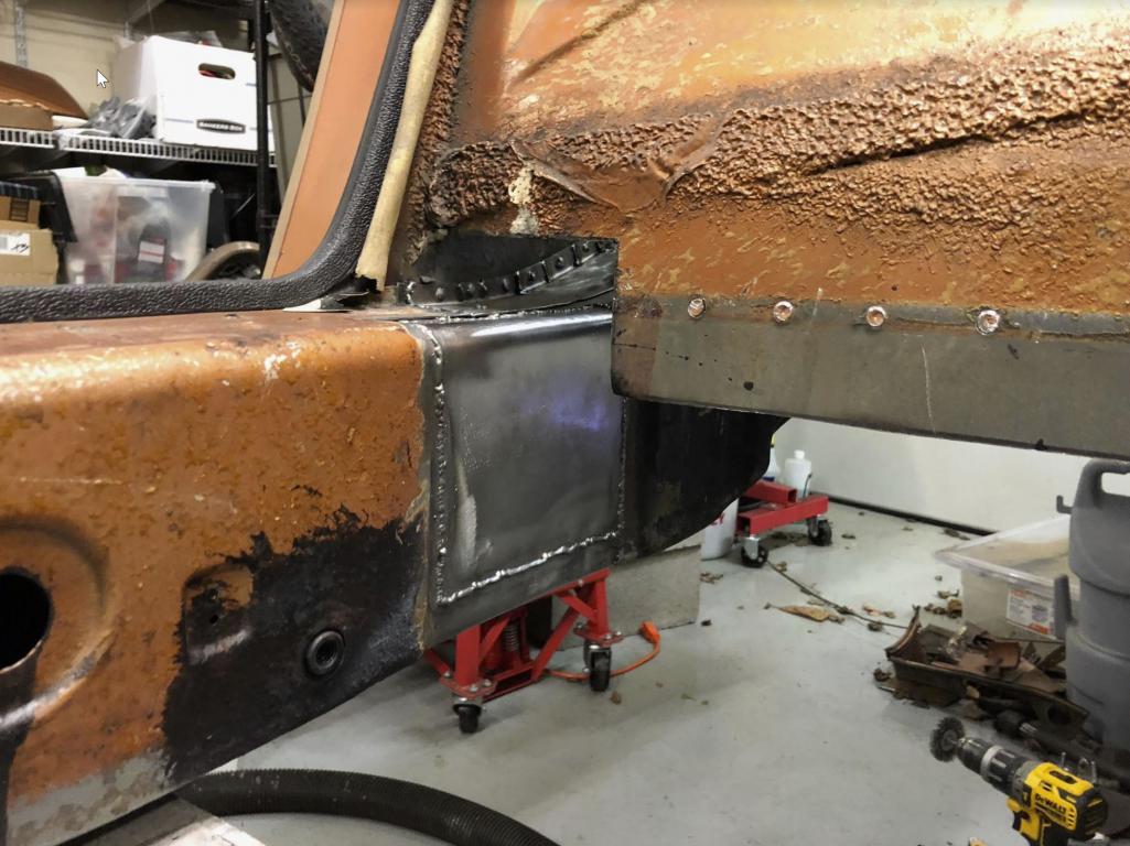 For the turbo dog house (this was a planning mistake, but it would do it again this way now that I have done it) i bought a section of a cut up trunk, and looked at it for a few hours to figure out how to cut it out to make it look as close to oem as I could, then cut some sheets with the cut off wheel and flap disc and cleaned it all up after welding. I also have some harbor freight electric shears I will use to get stuff down to more manageable size, and occasionally use the cuts. 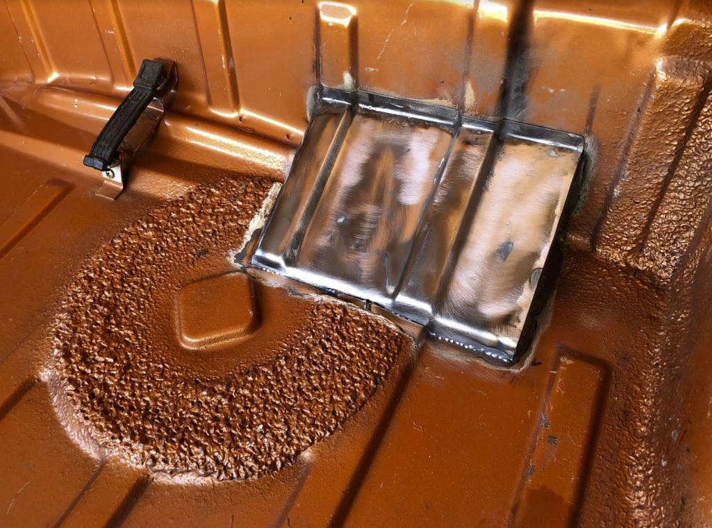 I have a similar process for tubing. I generally spend time mocking it up, buy a pile of mandrel bends, and cut it with a cutoff wheel. I like using wide masking tape to mark straight cuts (and try not to stretch it). The old "downpipe" for the original turbo was a stainless mandrel bend and some flanges welded on, then I had to fill a big spot to make the oval for the oval subaru wastegate configuration.. So I made a cardboard template, cut a piece of tube open along the weld, and smashed around various ipe wood forms until it fit. starting with the cardboard template. When it was close, I worked on clearancing both parts until I had close butt weld. 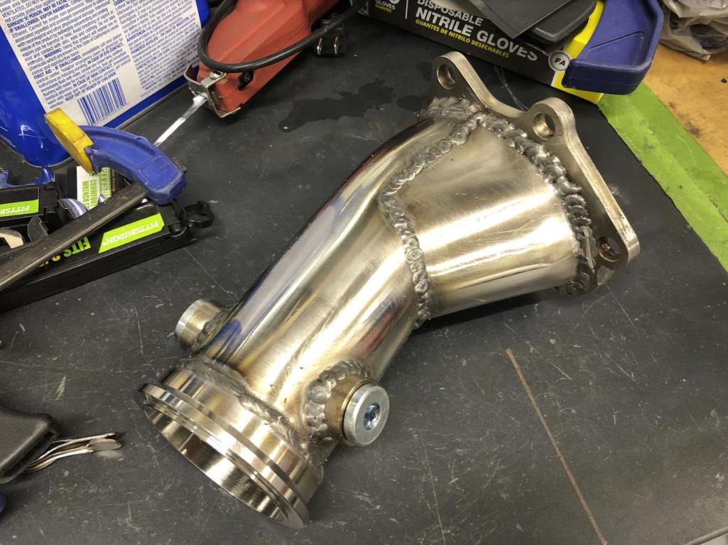 I used all straight tubes welded together for the tunnel, rear firewall, floor, etc. There might have been one or two bends in the sheet. I do all the bending with a vice, ipe wood tools, a 3 lb sledgehammer, and some knipex parallel jaw adjustable wrenches to help make clean bends in smaller parts. I will hit a foot long piece of ipe into a wide sheet width a sledgehammer to get a clean edge break too. 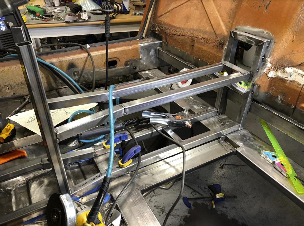 |
|
|
|
| waltonsm |
Jun 21 2021, 10:07 PM
Post
#33
|
|
Member Group: Members Posts: 93 Joined: 27-June 14 From: United States Member No.: 17,561 Region Association: Pacific Northwest |
QUOTE(mgarrison @ Jun 17 2021, 08:18 AM) Amazing Suby build! Incredible fab skills... :worship: Any additional details & pics you can share on radiator plumbing & pump. Any details on the Tilton pedal cluster install would be appreciated too. I'm early in the process of my Suby conversion. Looking to use a WRX engine & trans as well. After deciding to go with a race pedal cluster for tuning and adjustability. After making that decision, I decided the tilton 600 floor mount was the best option for me. I expected to need to repair the floor due to rust, but it ended being only light surface rust. Given that, I needed a way to mount the pedals in the right location, and get the braking pedal force into the floor. Goal was to be able to get the pedals just about as close to the firewall as the OEM config, but also be able to adjust out to dial the position in for the driver. You can see the corrugated floor reinforcement template I made from the initial cotton paper one to represent the thickness of the plate. 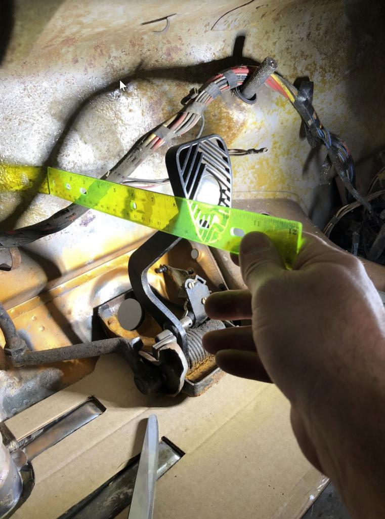 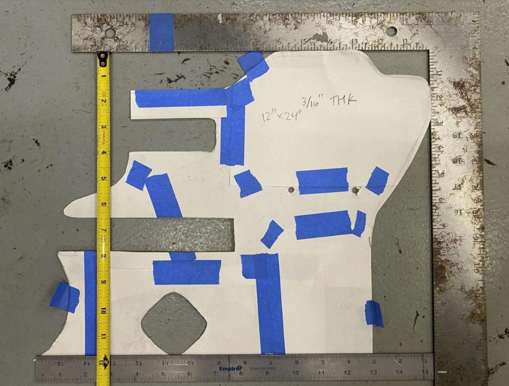 I drilled holes and welded in flange nuts from the back for the pedals to fasten to, coated it in weld thru primer, and stitched it to the floor I made a bolt on close out plate with a gasket and bulkhead tee fitting to go through the existing master cylinder hole to get the brake lines to the front brakes. 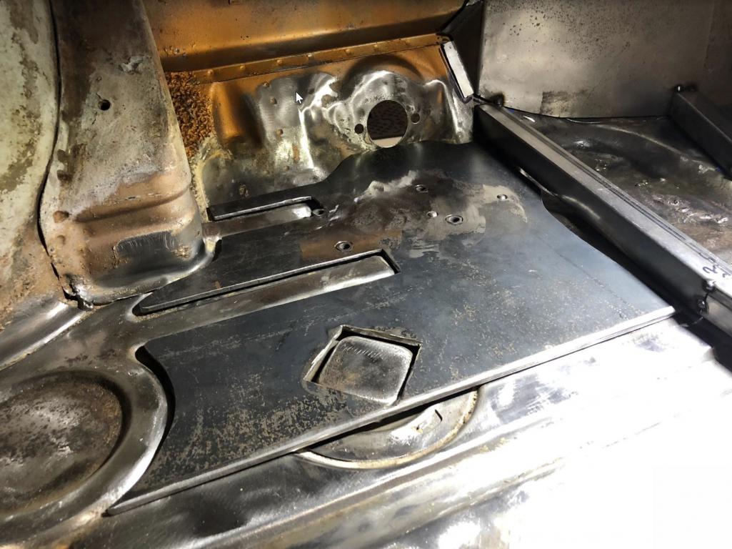 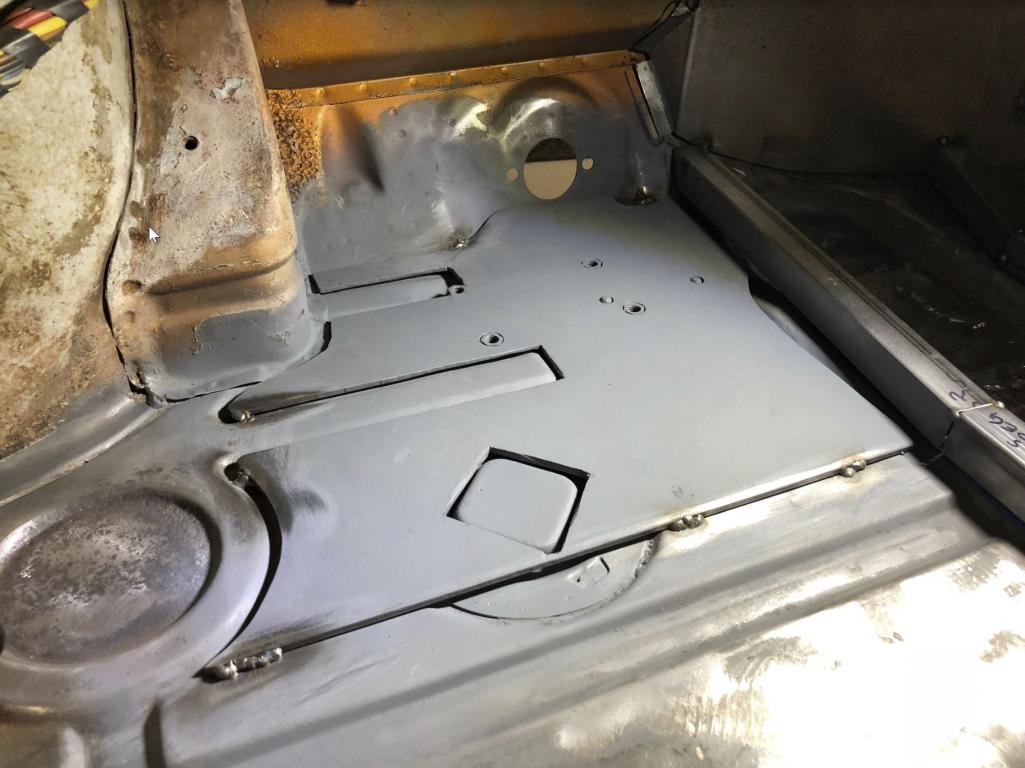 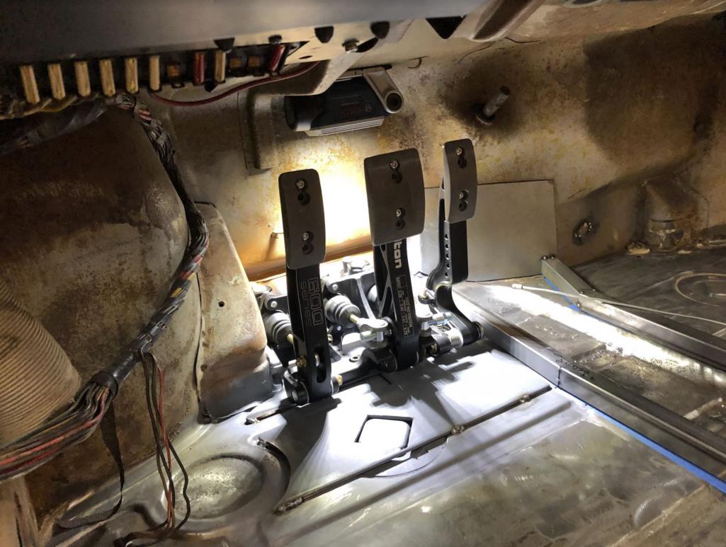 I made a bracket to fit the short triple reservoir system in order to mount it roughly where the OEM reservoir was. I have the cylinders sized to be stiff but very comfortable to drive on the street. Want to be able to control a 1st gear launch with a slightly stiffer than oem single disc clutch, and also made the brakes stiff enough to prevent me locking them up too easily. It has a balance bar for front/rear bias adjustment and an adjustable proportioning valve. I dialed all of this on the track with the current tires, and then biased it a bit for the street. 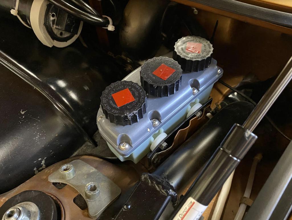 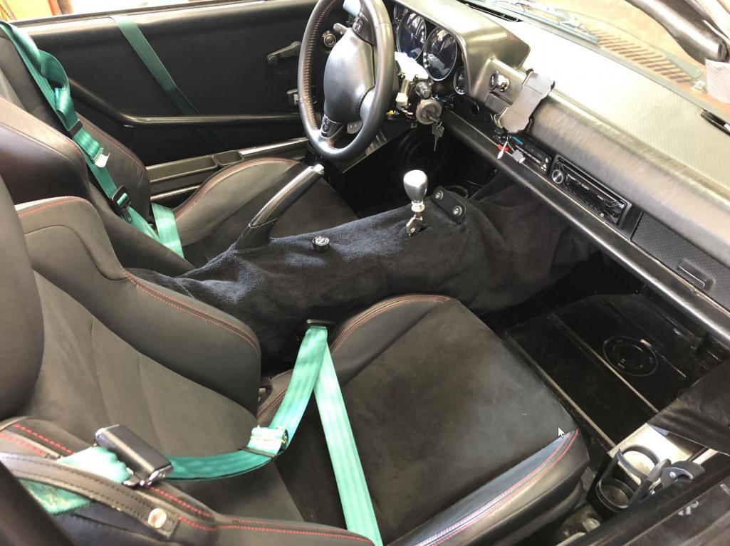 Currently it looks like this with all the lines and sensors attached. 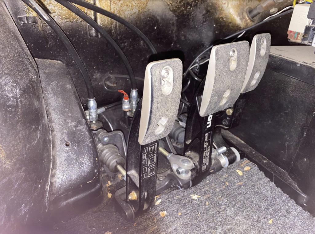 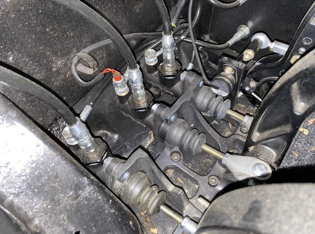 |
|
|
|
| waltonsm |
Jun 21 2021, 10:39 PM
Post
#34
|
|
Member Group: Members Posts: 93 Joined: 27-June 14 From: United States Member No.: 17,561 Region Association: Pacific Northwest |
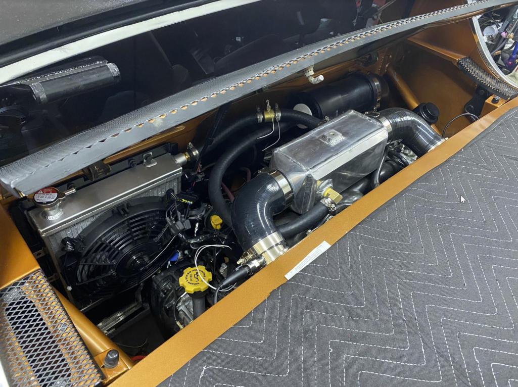
QUOTE(mgarrison @ Jun 17 2021, 08:18 AM) Amazing Suby build! Incredible fab skills... :worship: Any additional details & pics you can share on radiator plumbing & pump. Any details on the Tilton pedal cluster install would be appreciated too. I'm early in the process of my Suby conversion. Looking to use a WRX engine & trans as well. Radiator plumbing was a pain, and was the primary reason I decided to build the center tunnel, that and to hide a bunch of other stuff. My solution was enables by some crazy flexible green stripe gates hose. This stuff is nuts. I used an aftermarket 240sx race radiator, with two fans running of the WRX oem controller and current 185 and 205 (I think set points) 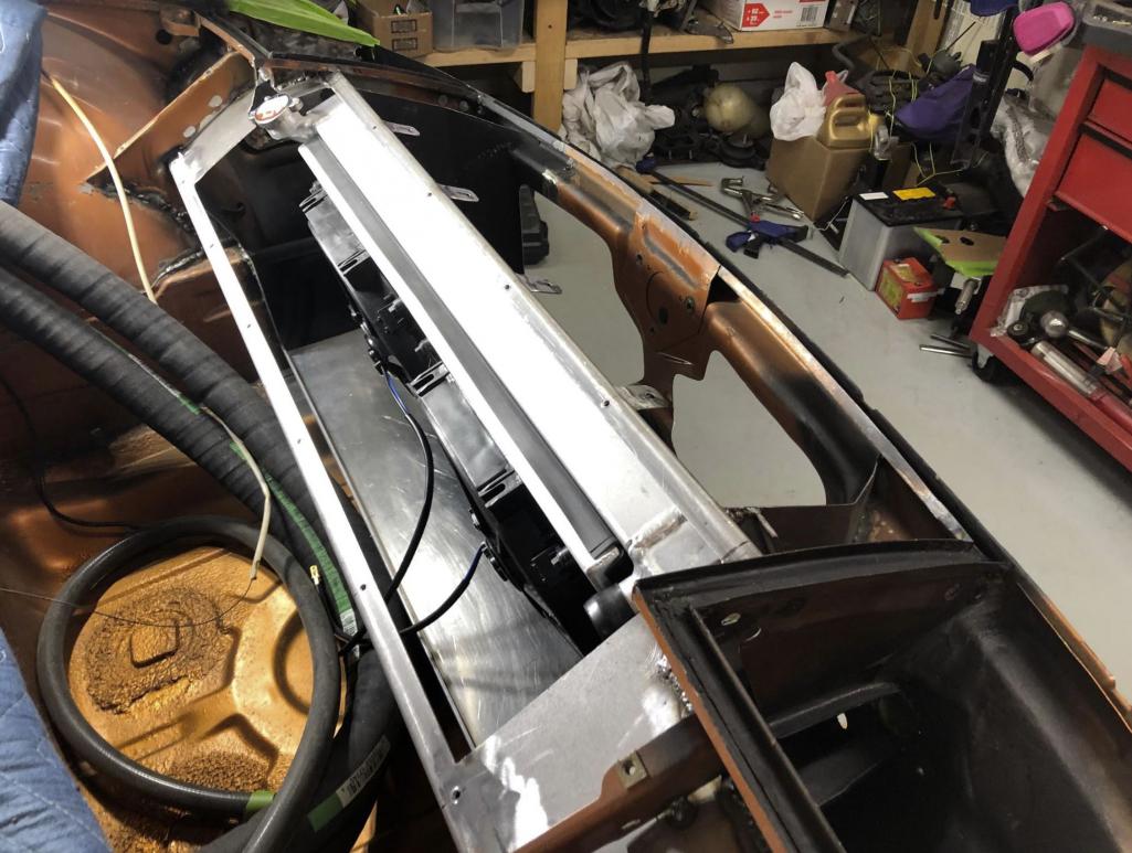 You can see where the upper and lower hoses, and the heater core hose penetrate the fuel tank bulkhead. This is a test fit before I installed the edge protection/grommets to the sheet metal.  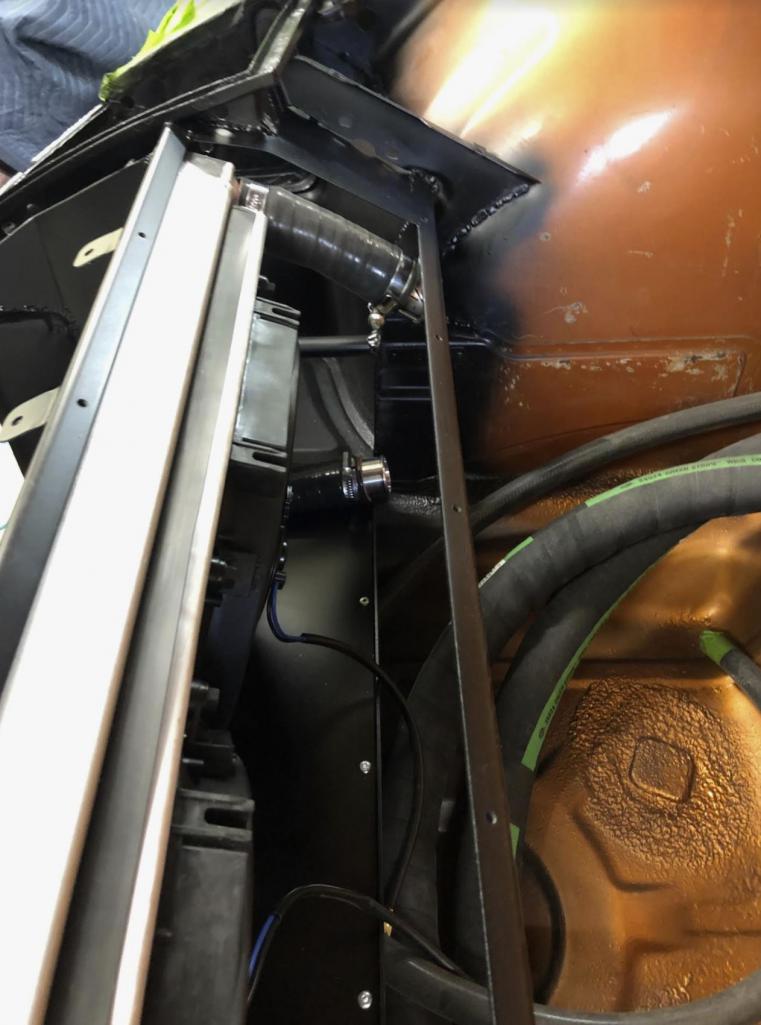 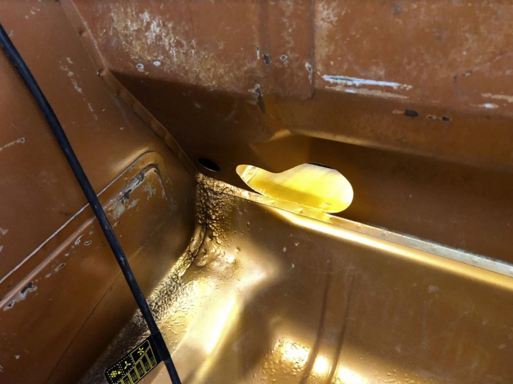 I welded in 1.5" steel heater tube bends through the front and rear firewall to attach the hoses on both sides. Worked great, but this is a huge pain to work on. I hope I never have to see this again. 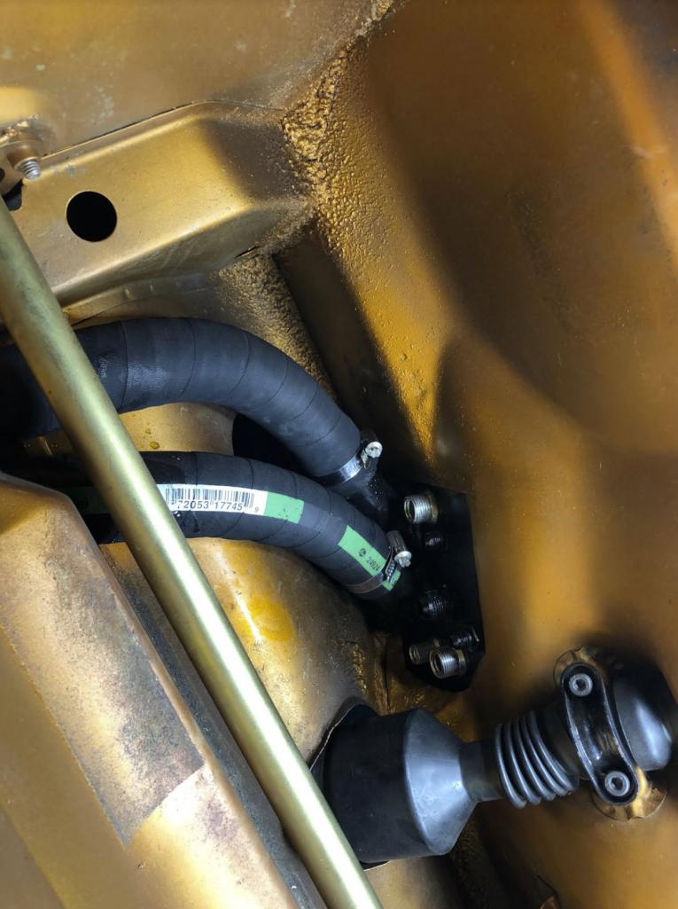 I used 1.5" reinforced silicon in the tunnel, with nice bandclamps (concerned iIwill have to see this again..) I then wrapped all the hot lines with nice armaflex insulation to reduce the heat load into the tunnel. I don't have any pics of this at the moment. 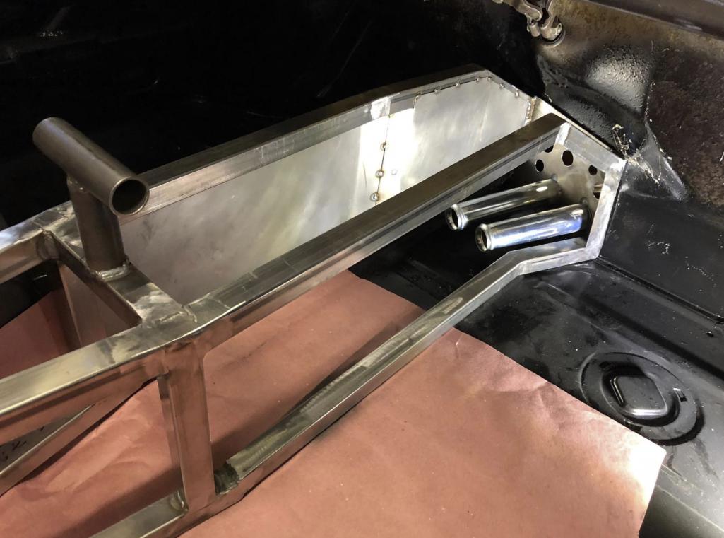 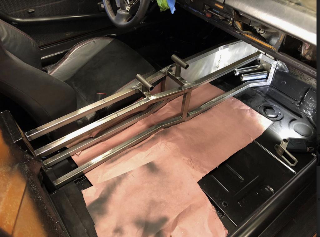 In the front firewall I used 45 deg bends, in the rear firewall I used 90 deg bends. It was a tight fit in the tunnel and I had to do some weird orientation to make it installable. But you don't see any of that on the outside. You can see the tubes running horizontal and parallel to the firewall. I did this so I could get the degrees of freedom I needed for installation and engine movement using long leg reinforced silicone elbows. These attach to the stock WRX water pump and upper hose location. 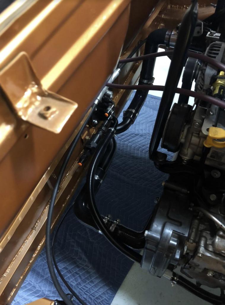 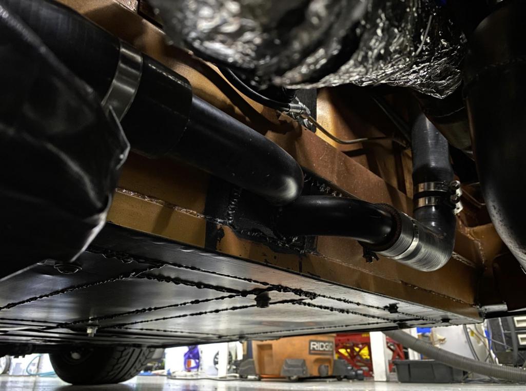 Now the real fun part doesn't have any pictures here, but is very important.. I added a highpoint bleed off of the upper coolant line off the block, this bleeds back to an oem style upper reservoir that feeds the post shutdown turbo convection loop per oem config. I also have the expansion tank off the upper reservoir. I have had zero issues bleeding this system since assembled, and it runs at the nominal setpoints between 185 and 205. I was concerned about it, but found some good resources in the 818 forums. |
|
|
|
| waltonsm |
Jun 21 2021, 11:10 PM
Post
#35
|
|
Member Group: Members Posts: 93 Joined: 27-June 14 From: United States Member No.: 17,561 Region Association: Pacific Northwest |
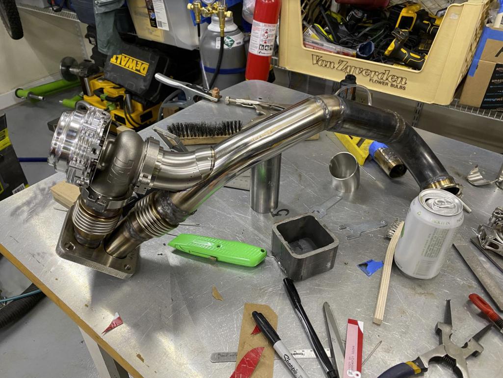
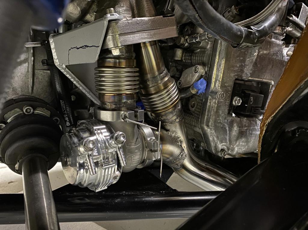
Will write up the new turbo swap next.
      |
|
|
|
| mgarrison |
Jun 22 2021, 09:05 AM
Post
#36
|
|
Member Group: Members Posts: 416 Joined: 14-February 20 From: Chandler, AZ Member No.: 23,922 Region Association: Southwest Region |
Thanks! Really appreciate all the details and pics! (IMG:style_emoticons/default/beerchug.gif)
|
|
|
|
| waltonsm |
Mar 24 2022, 01:58 PM
Post
#37
|
|
Member Group: Members Posts: 93 Joined: 27-June 14 From: United States Member No.: 17,561 Region Association: Pacific Northwest |
It is time for an update on what I have been up to with this car. I spent a bunch of time enjoying it over the last few years, and did several road trips and used it as my daily driver for most of the summer.
  That includes driving to trailheads on on forest roads to go hiking and camping. I got turned around a couple times, and started getting the itch to put together a more capable offroad set of wheels/tires/suspension. So I could change it up when I feel like it. I started collecting some parts to work on the project over the winter. Instead I had the opportunity to get started earlier... on the way to the hike below. I had a pretty amazing bang while driving 70mph in 5th gear over Snoqualmie Pass. After the shock and some quick troubleshooting at 50mph, decided it to drive to the ranger station and have my friends pick me up for the hike and deal with the problem later. 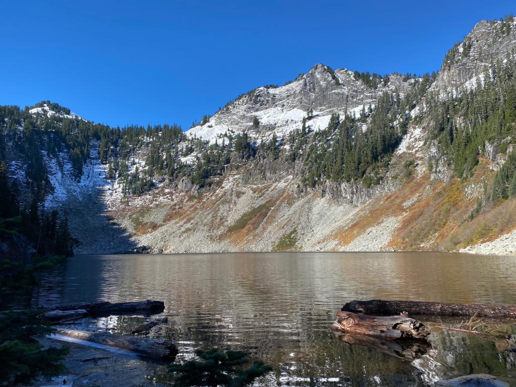 I had a great time talking to the driver on the way back to Seattle, brainstorming scenarios of what might have gone wrong. 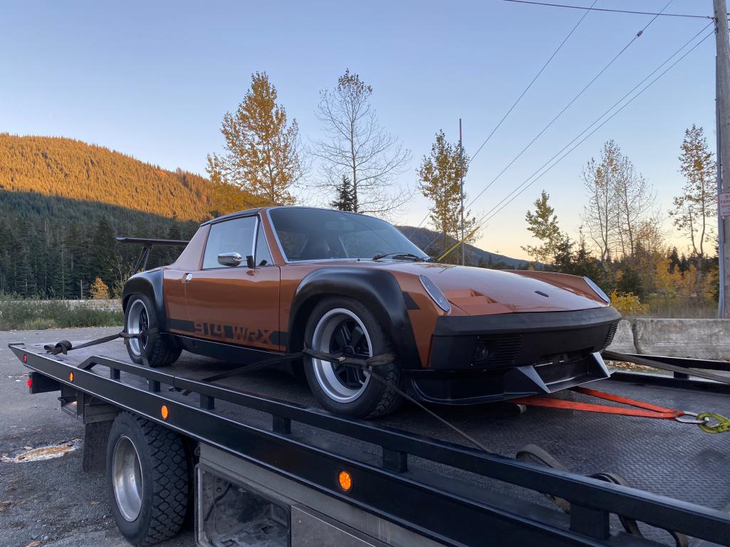 |
|
|
|
| waltonsm |
Mar 24 2022, 02:24 PM
Post
#38
|
|
Member Group: Members Posts: 93 Joined: 27-June 14 From: United States Member No.: 17,561 Region Association: Pacific Northwest |
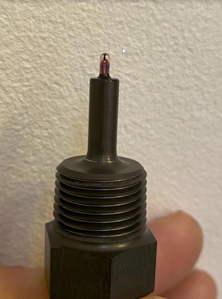
I was pretty certain the issue was with the final drive from the beginning, but wanted to methodically evaluate starting with scoping the intake, exhaust, turbo, cylinders, leak down test, compression test, then move on to transmission assessment.
I spent the entire next day going through the engine.. all looked great. 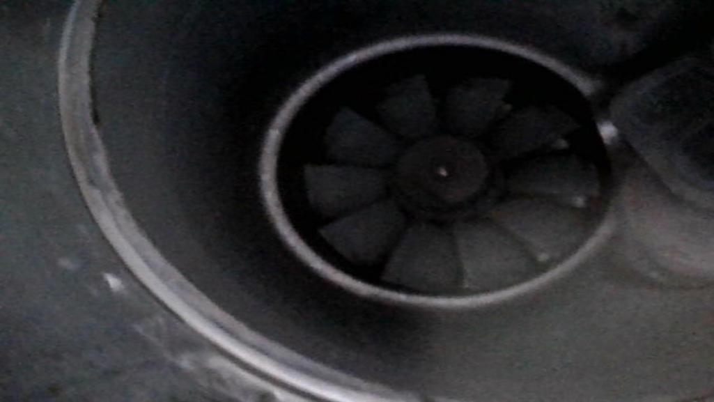 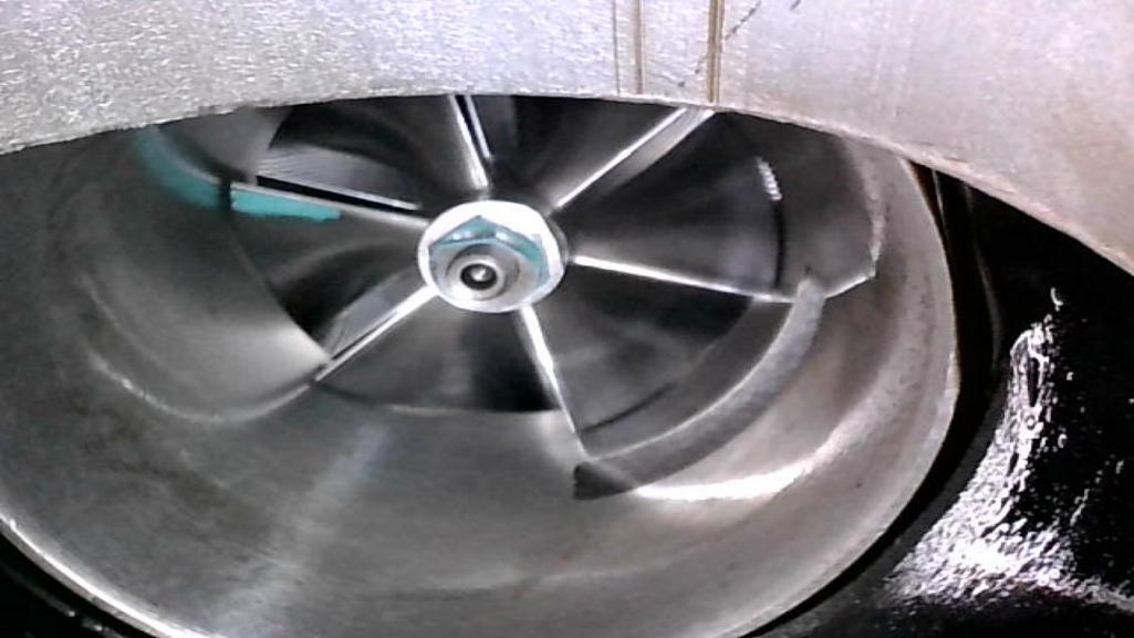  and then the transmission.. not so great. Open the drain plug to find some nice large teeth. 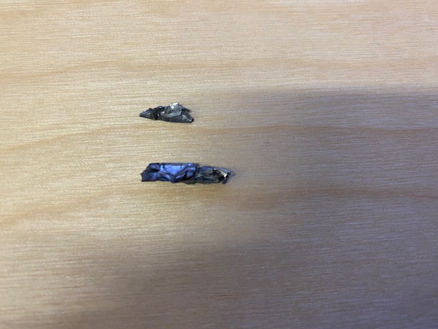 And further disassembly and inspection shows some fun crack growth to failure. And now I know what the bang was. 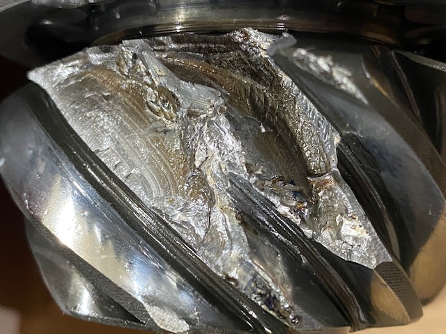 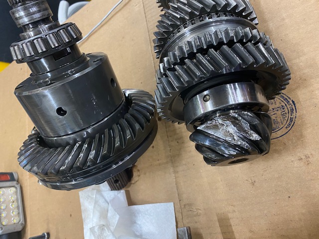 In hindsight, there were a couple indicators of a damaged pinion when I bought the used transmission out of a wrecked car... At zero backlash, I could feel a more binding during part of the revolution when setting backlash and checking pinion depth when I installed the torsen lsd. The donor car had a front right collision that could have damaged the pinion, or maybe it was just a manufacturing defect, or maybe I set it up wrong. It lasted about 10000 miles in this configuration after the roughly 50K in the original WRX. Now I obviously had a new task prior to the offroad conversion. But the COVID impacts on the workforce, logistics, supply chain, stretched this out. It also seems that manufacturers used this as an opportunity to obsolete a lot of spare parts I was interested in, so it took some digging. |
|
|
|
| waltonsm |
Mar 24 2022, 02:52 PM
Post
#39
|
|
Member Group: Members Posts: 93 Joined: 27-June 14 From: United States Member No.: 17,561 Region Association: Pacific Northwest |
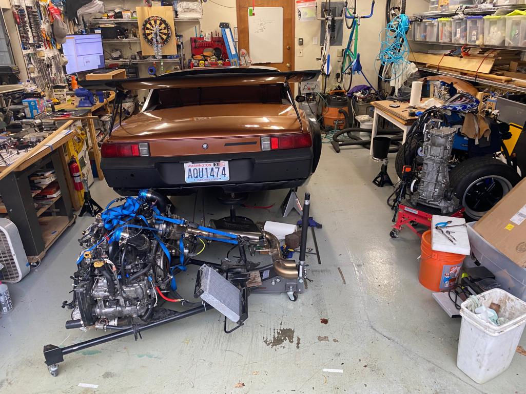
The good news is that the engine and transmission are pretty straightforward for me to get out, and into the car on my own. The cradle works well, and with some other jacks and ratchet straps I really don't need to lift anything. I can remove it all less than 3 hours, and install it all in about 8 hours, including fluids.
 And another photo of trans disassembly/discovery 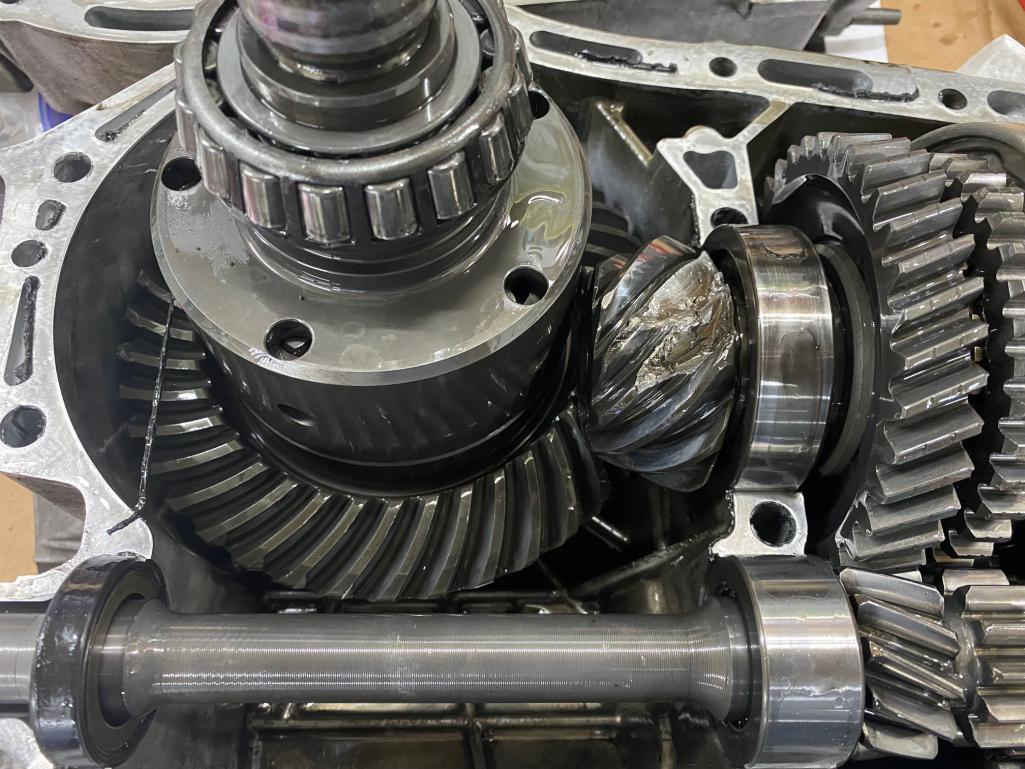 Since I don't have any of the special tools, I used a lot of different sized sockets, bearing tools, and made several different wood v-blocks out of ipe to assist with disassembly and reassembly of the shafts/gears. There was more time spent there than I want to remember. But, I got it done with the help of a friends 10 ton bottle press. Assembled shafts and then case below. I ended up using oem/mmp polished gears in older 5spd STI ratios, and changed the final drive. I was working to improve the gear spacing, along with reliability. There were a bunch of considerations for strength/driveability that I was considering, but I am also adding torque/boost by gear into my tuning as part of the plan. 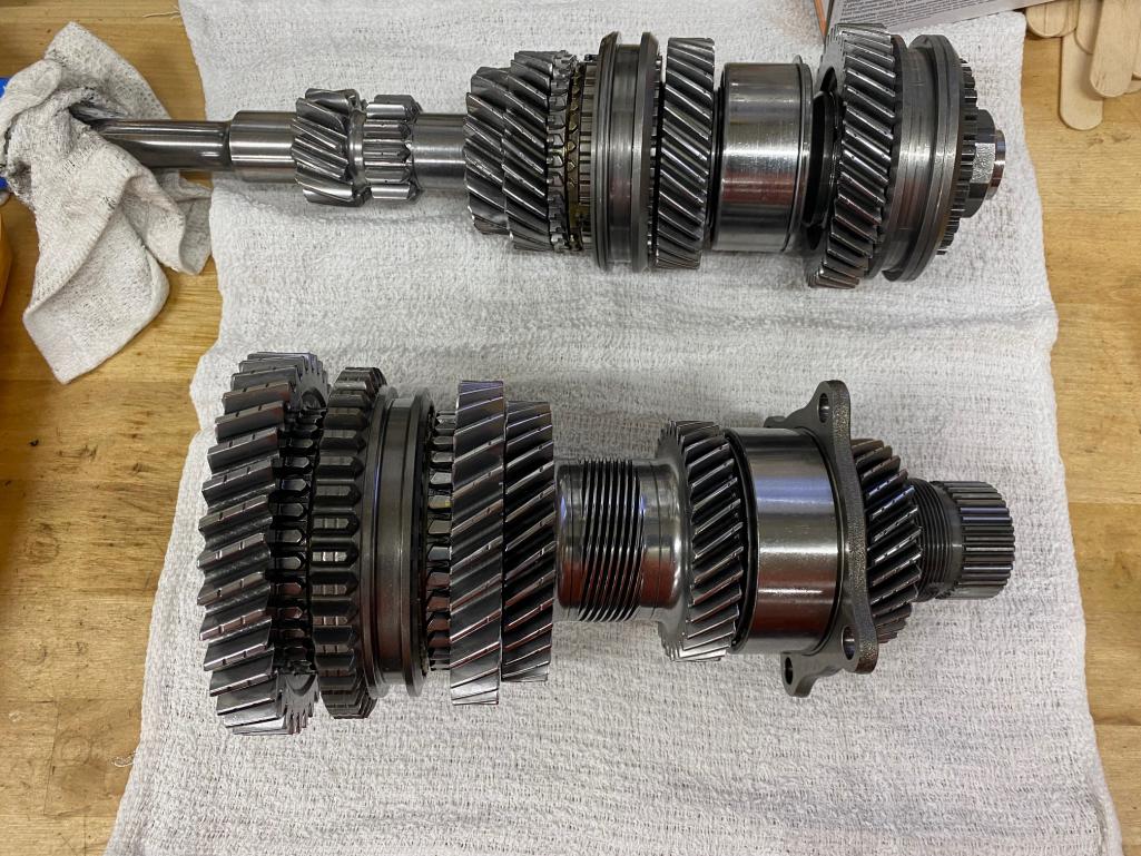 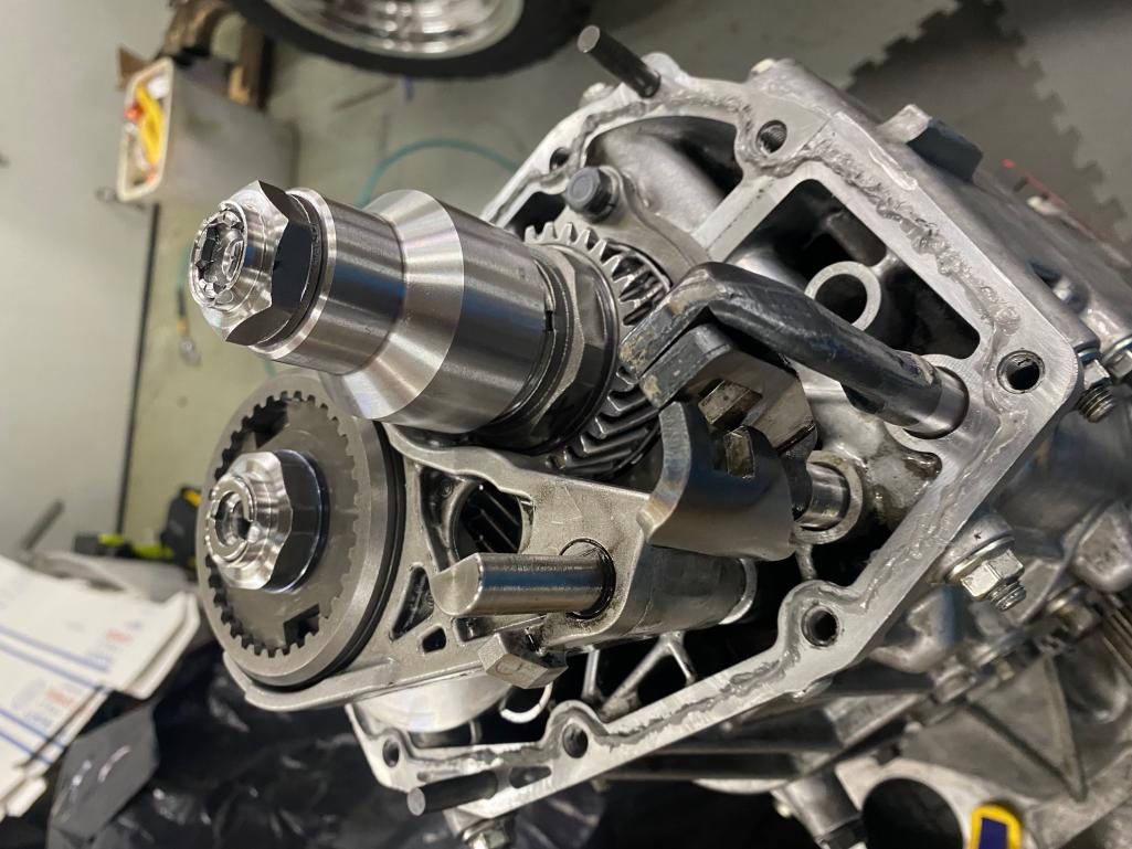 |
|
|
|
| waltonsm |
Mar 25 2022, 11:50 PM
Post
#40
|
|
Member Group: Members Posts: 93 Joined: 27-June 14 From: United States Member No.: 17,561 Region Association: Pacific Northwest |
While waiting for transmission parts I decided to revisit a backburner project. Now that I will have tires that are capable of below freezing temperatures, I need to actually get a heater core in the car. The heated seats, down blanket, and fur hat work OK, but don't do much for defrosting and keeping the feet warm.
I started this project a couple of years ago, but it stalled several times because I was overthinking it while retaining the option for A/C. Odds are low that will happen, and I will learn from this project anyway. I set off to find the smallest heater core of the right form factor and outlet configuration that I could buy. So many of the tiny ones have odd plumbing routing to fit in tiny dashboards (e.g. suzuki samurai). I ended up with a mid 90s mazda 626 core. 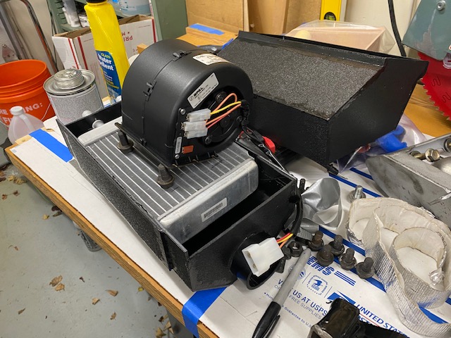 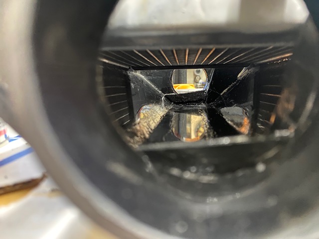 The airbox fits in a pretty small space, and I was planning on retaining all the original controls for the fan, heat, and flow directions from the dash, along with the drains and existing plumbing. The only thing removed is the original intake lines from the exhaust heat exchangers. I maintained filtering, water trap, and drains with this design and it is serviceable, about as serviceable as the original design once you get the tank out. At least I have a top exit fuel pump now. I also needed to add a heater control valve inline with the heater core to ensure I can still turn it off when I don't want it. 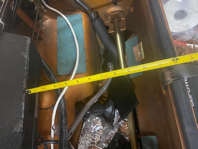 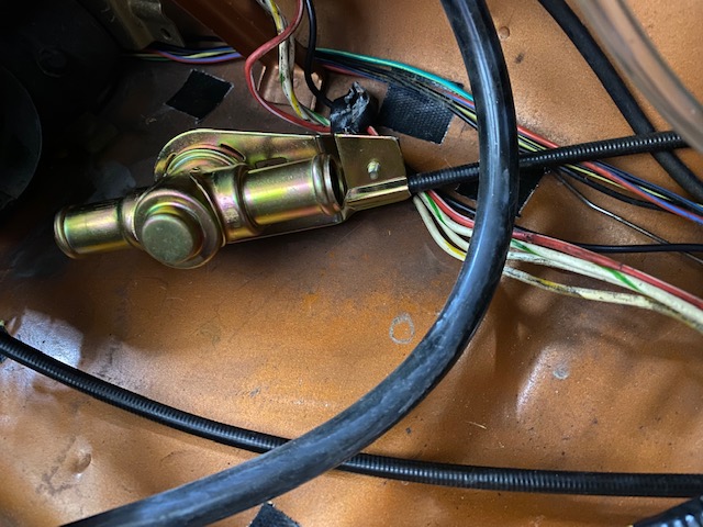 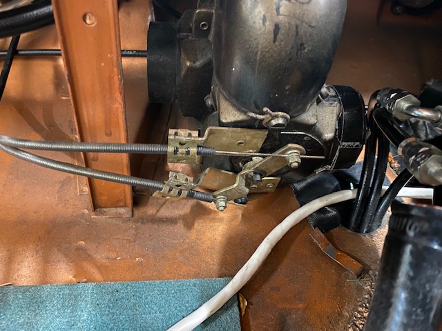 The whole thing fit together pretty well. I might do it slightly differently a second time. but electric shears, abs sheet, and abs cement worked great for this project. 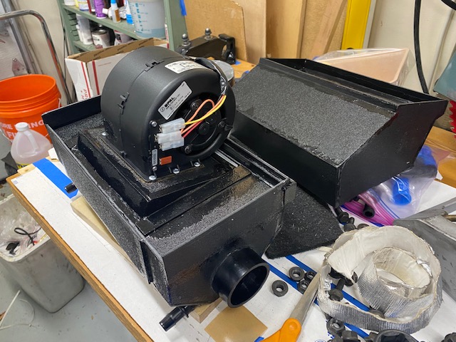 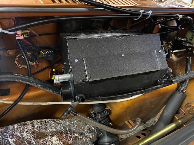 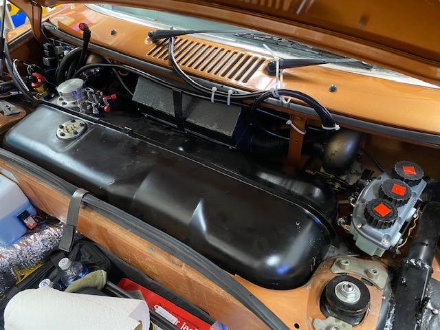 Then came the wiring... I had forgotten about my prior plan to make this work, but happened to have all of the parts on hand. The 914 switches the resistor grounds in the oem fan airbox using the slider controls on the dash. Most modern stuff switches the resistors on the hot side, if it has resistors at all. The SPAL fan I bought does indeed have resistors, and I needed to switch the hot. After figure out which pins are what, I bundled up a harness packed with relays to convert the switched ground to switched hot. Maybe someone here will find these numbers and sketch useful. I ended up using my $50 wifi/cellphone borescope to pick out wiring colors under the dash (because I had already cut the harness near the fan) I did test this harness before bundling everything up, so of course this is the time I got it right on the first try. 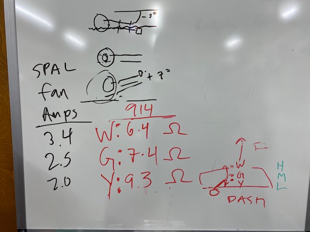 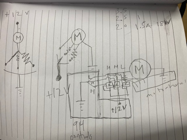 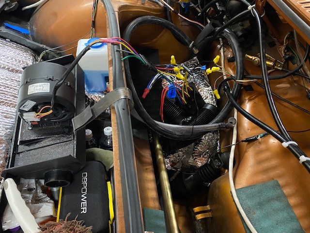 |
|
|
|
|
1 User(s) are reading this topic (1 Guests and 0 Anonymous Users)
0 Members:

|
Lo-Fi Version | Time is now: 3rd July 2026 - 08:02 PM |
Invision Power Board
v9.1.4 © 2026 IPS, Inc.