|
|
|
Porsche, and the Porsche crest are registered trademarks of Dr. Ing. h.c. F. Porsche AG.
This site is not affiliated with Porsche in any way. Its only purpose is to provide an online forum for car enthusiasts. All other trademarks are property of their respective owners. |
|
|

  |

| BillC |
 Jan 30 2021, 05:10 PM Jan 30 2021, 05:10 PM
Post
#101
|
|
Senior Member  Group: Members Posts: 732 Joined: 24-April 15 From: Silver Spring, MD Member No.: 18,667 Region Association: MidAtlantic Region |
So I finally managed to get back to the car today, for a few hours. I cut and tacked-in a patch for the hole in the latch area.
Here's the hole where I cut out the rusty latch area, after it had been soaked with Ospho: 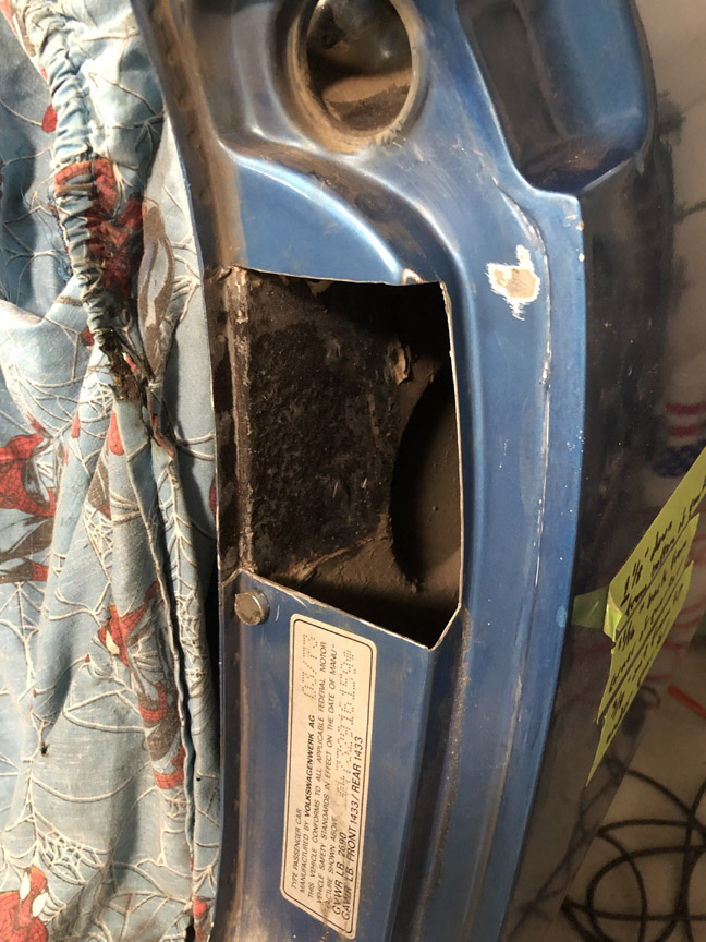 Not shown: once the Ospho was dry, I sprayed the area inside the quarter with high-zinc paint. Here's the patch fitted, and then tacked in place with the tackwelds ground down. 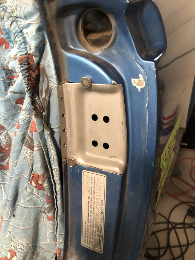 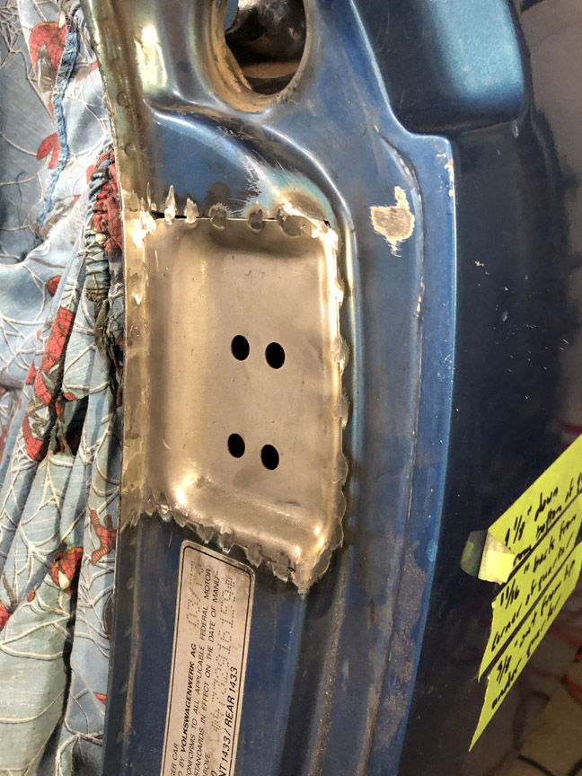 The plan for tomorrow, assuming the weather cooperates, is to finish welding in the patch and then get started on the reinforcement behind the latch. |
   |

 
|
| Montreal914 |
Jan 30 2021, 09:09 PM
Post
#102
|
|
Advanced Member Group: Members Posts: 2,135 Joined: 8-August 10 From: Claremont, CA Member No.: 12,023 Region Association: Southern California |
QUOTE(BillC @ Jan 17 2021, 12:16 PM)  Time to take on the last rusty area I've found -- the driver's side latch post and jack point. Here's what it looks like to start: This side doesn't look much worse than the passenger side. However, I'm going to have to replace the jackpoint tube, since I poked through the metal at the bottom when cleaning out rust. Also, when I unscrewed the latch post, the screw plate underneath wouldn't move. Turns out, that area was packed full of this god-awful light-brown sand. The only heavily-rusted places I've found on this car are places where the sand was packed in -- both jackpoints, the lower driver's latch panel where the vent tubes run and (of course) the pocket for the latch post screw plate. Some DAPO must have driven this car on the beach multiple times (or just one time very enthusiastically). With some poking and prodding, I finally freed up the screw plate. I also knocked a surprising amount of sand on the floor -- could the inside of that pocket be like a tardis (bigger on the inside)? Unfortunately, it turned out that the backside of the pocket is rusted out, so I'll need to purchase or make a replacement. I already have a replacement latch panel, latch reinforcement and screw plate, but can't find a replacement pocket cap (or whatever it would be called). I'll make one if I have to, but would like to see if a new one is commercially available. Does anyone know if a replacement for that pocket/cap is available? I've already checked Restoration Design and AutoAtlanta, but can't find the part on either site. Any leads are appreciated -- looking for the sheet metal piece circled in red. I did my own... (IMG:style_emoticons/default/smash.gif) (IMG:style_emoticons/default/welder.gif) Here: http://www.914world.com/bbs2/index.php?s=&...t&p=2887081 On your post #96, how did you remove the torsion bars of the engine lid? Was that scary like the ones for the rear trunk? |
 |
|
| BillC |
Jan 31 2021, 08:42 AM
Post
#103
|
|
Senior Member Group: Members Posts: 732 Joined: 24-April 15 From: Silver Spring, MD Member No.: 18,667 Region Association: MidAtlantic Region |
QUOTE(Montreal914 @ Jan 30 2021, 10:09 PM) I did my own... (IMG:style_emoticons/default/smash.gif) (IMG:style_emoticons/default/welder.gif) Here: http://www.914world.com/bbs2/index.php?s=&...t&p=2887081 On your post #96, how did you remove the torsion bars of the engine lid? Was that scary like the ones for the rear trunk? @Montreal914 Thanks for the link! That's how I was thinking of making mine. Only difference is that I'll be able weld it to the reinforcement bracket before I weld the bracket in place. The engine lid torsion bars were very easy to remove. Much less energy involved than the trunk lid springs. First step is to unbolt the deck lid from the car. Then, lay the deck lid upside down on some towels. Then, you'll be able to push down on the torsion bar at the hinge end to slide it out of the notch in the hinge. Then, just unscrew the block in the middle, and work the torsion bars out of the hole on the other end. I recommend taking some pictures of everything assembled before you take it apart, especially if it's going to be a while before reassembly. I also used masking tape to label each end of the bars, so I could get them back in the same way. |
|
|
|
| Montreal914 |
Jan 31 2021, 10:28 AM
Post
#104
|
|
Advanced Member Group: Members Posts: 2,135 Joined: 8-August 10 From: Claremont, CA Member No.: 12,023 Region Association: Southern California |
QUOTE(BillC @ Jan 31 2021, 06:42 AM) QUOTE(Montreal914 @ Jan 30 2021, 10:09 PM) I did my own... (IMG:style_emoticons/default/smash.gif) (IMG:style_emoticons/default/welder.gif) Here: http://www.914world.com/bbs2/index.php?s=&...t&p=2887081 On your post #96, how did you remove the torsion bars of the engine lid? Was that scary like the ones for the rear trunk? @Montreal914 Thanks for the link! That's how I was thinking of making mine. Only difference is that I'll be able weld it to the reinforcement bracket before I weld the bracket in place. The engine lid torsion bars were very easy to remove. Much less energy involved than the trunk lid springs. First step is to unbolt the deck lid from the car. Then, lay the deck lid upside down on some towels. Then, you'll be able to push down on the torsion bar at the hinge end to slide it out of the notch in the hinge. Then, just unscrew the block in the middle, and work the torsion bars out of the hole on the other end. I recommend taking some pictures of everything assembled before you take it apart, especially if it's going to be a while before reassembly. I also used masking tape to label each end of the bars, so I could get them back in the same way. Great! Thank you for the procedure, and yes, there could definitely be time between the disassembly and re-assembly. I need to replace one of the mounts on the firewall and I think it will be easier to set the location if I can freely open and close the lid without fighting the torsion bars. The other mount was repaired in the past and the whole lid may not be properly lining up, so that might end up being a complete alignment job. Good luck with your project, looks like you are making great progress. (IMG:style_emoticons/default/smilie_pokal.gif) |
|
|
|
| TX914 |
Jan 31 2021, 10:32 AM
Post
#105
|
|
Alan-B Group: Members Posts: 177 Joined: 27-July 14 From: USA Member No.: 17,689 Region Association: None |
Very nice work.
Regarding the torsion bars - If there is any sag in the engine lid when open, you can swap the torsion bars (so that they bend in the opposite direction) and it'll be like new. |
|
|
|
| BillC |
Jan 31 2021, 11:49 AM
Post
#106
|
|
Senior Member Group: Members Posts: 732 Joined: 24-April 15 From: Silver Spring, MD Member No.: 18,667 Region Association: MidAtlantic Region |
I finished welding in the patch and grinding it down this morning. Here's what it looks like:
 After I finished welding and grinding, I tried fitting the reinforcement panel behind the new panel. Unfortunately, the holes don't quite line up, they're about 1/8" off each other. So, after lunch, I'll first measure the locations for the screw holes in that panel, using the other side as a guide, and adjust whichever set of holes needs adjusting to match. Then, I'll start on the adding the nut plate and cover to the reinforcement that goes behind the panel and weld that in too. |
|
|
|
| BillC |
Feb 1 2021, 06:20 PM
Post
#107
|
|
Senior Member Group: Members Posts: 732 Joined: 24-April 15 From: Silver Spring, MD Member No.: 18,667 Region Association: MidAtlantic Region |
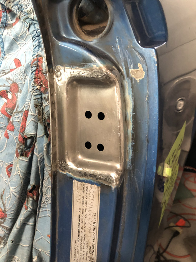
I measured the holes in the driver's side panel against the passenger side. The height of the holes is the same (yay!), but the driver's side holes are 1/8" further inward than the passenger side (boo!). But, since the cars were hand-assembled, I wasn't completely willing to trust the measurements. So, I remounted the door and checked the latch plate fitment, because now is the time to fix any fitment issues rather then after everything is assembled and painted.
Turns out the measurements were right, and the holes needed to be moved/slotted so the latch plate would end up in the right spot. Only took a few minutes with a rat-tail file, but now I have slots where there should be just holes. 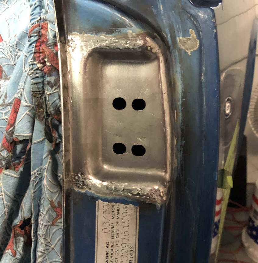 I'm not completely sure if I should leave the slotted holes like they are or if I should weld up the incorrect areas. The perfectionist in me is screaming "weld 'em up!", but my pragmatist side is saying that no one will see the holes once the car is reassembled and to just leave them alone. What do y'all think? So, with the door post more-or-less fettled, time to look at the parts that go behind the door post. Here are the parts I removed and the new parts from Restoration Design: 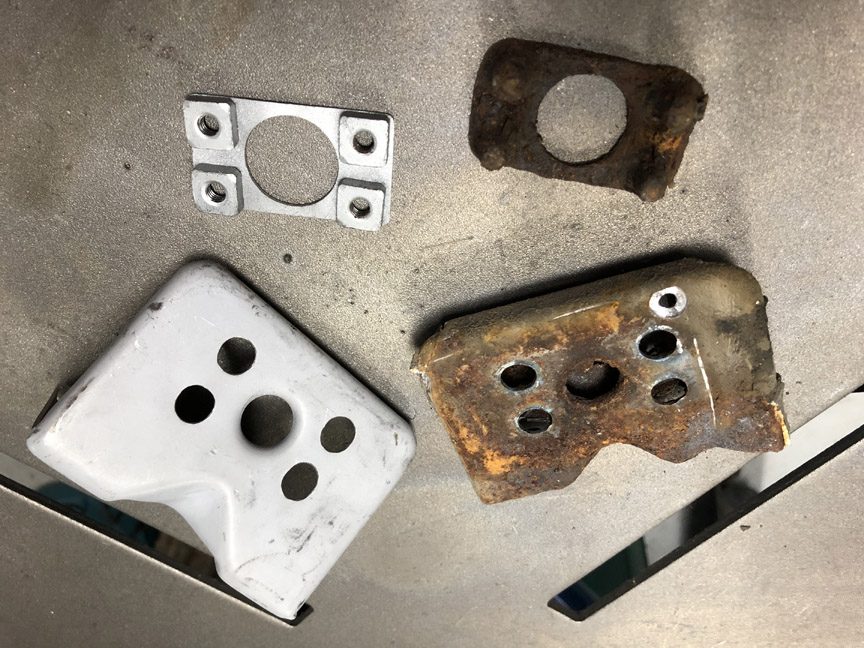 Working from the inside out means starting with the nut plate. The old plate is just too rusty to use, but the new plate doesn't have the deep holes of the old one. 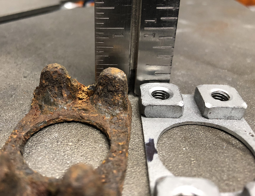 So I decided to add deep holes to the new plate. First step was to weld on some 8mm tubes to give depth (thanks for the tubes, @Superhawk996 ). To make the tubes align, I first screwed a long bolt into a hole and then slid the tube over. 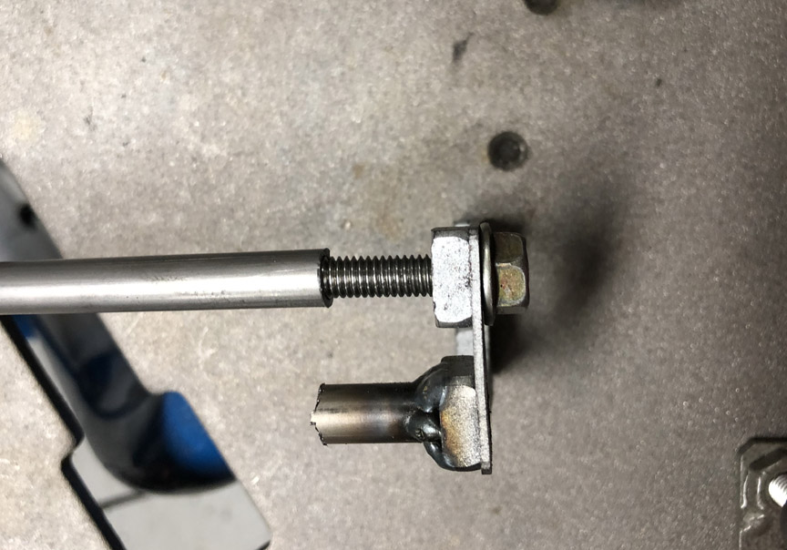 Once welded, the bolt is removed and the tube is cut a little long. After all four tubes were added, I ground them to length. 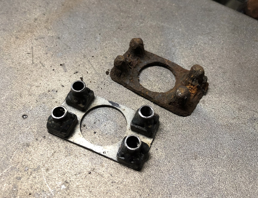 Finally, I capped the tubes with a bit of weld. 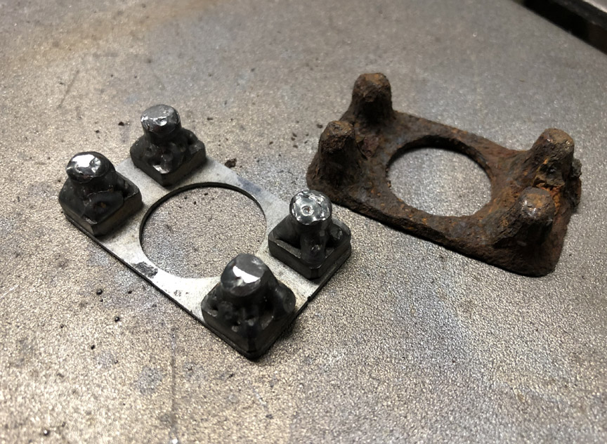 The part was then wire-brushed, had a tap run through each hole and finally painted in high-zinc paint. Once the paint is dry, it'll be ready to install under the cap I still need to make. |
|
|
|
| Superhawk996 |
Feb 2 2021, 06:41 AM
Post
#108
|
|
914 Guru Group: Members Posts: 7,886 Joined: 25-August 18 From: Woods of N. Idaho Member No.: 22,428 Region Association: Galt's Gulch |
(IMG:style_emoticons/default/biggrin.gif) Nice work. Very creative use of the tube. I love it. Glad to see it going to good use. Otherwise, it would just be sitting in my scrap metal bin, waiting for some unforseen need that may never happen.
|
|
|
|
| BillC |
Feb 6 2021, 05:20 PM
Post
#109
|
|
Senior Member Group: Members Posts: 732 Joined: 24-April 15 From: Silver Spring, MD Member No.: 18,667 Region Association: MidAtlantic Region |
Time to work on the latch plate support bracket.
First step was to put some M6 screws in the nut plate and mark out the travel limits of the plate on the bracket (slide the plate in each direction and then mark with a sharpie): 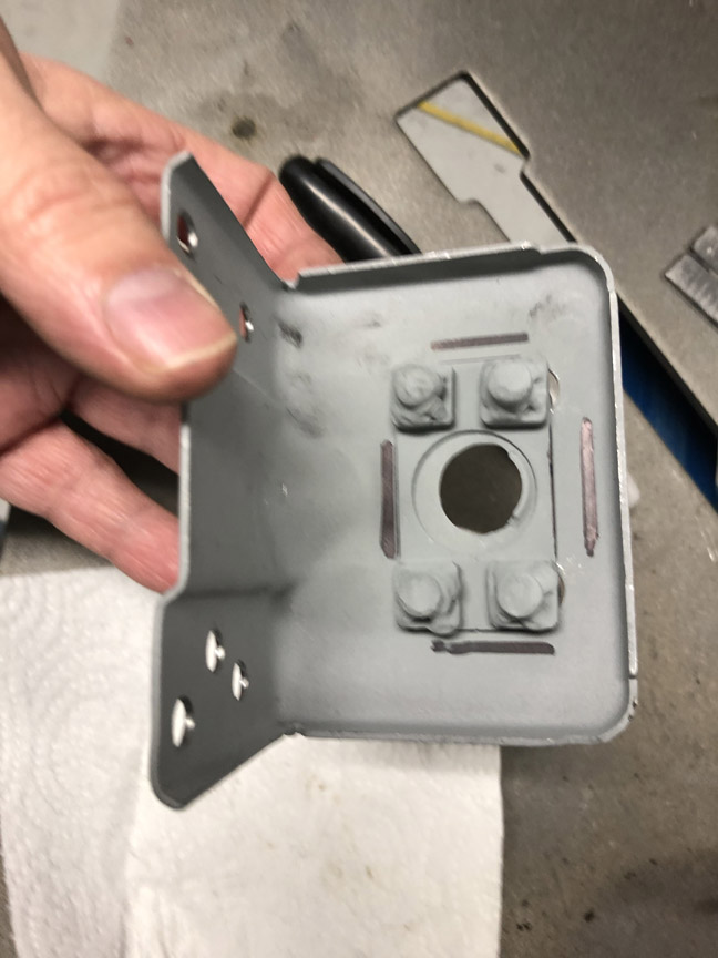 Then, I CAD'ed up a box to fit over the nut plate. In case you didn't know, this is Cardboard Aided Design -- 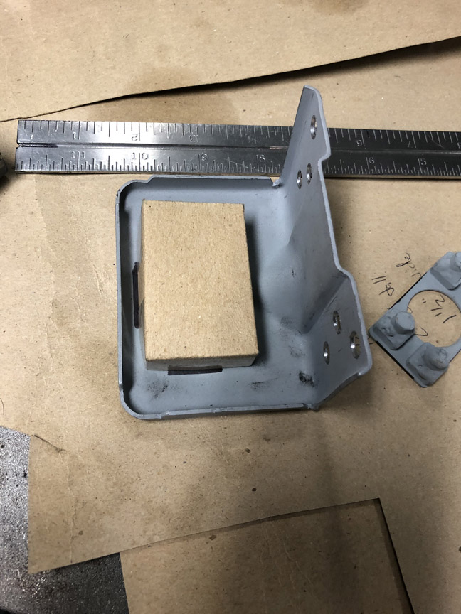 Then, I transferred the design to some sheet metal, cut it out and welded up the corners: 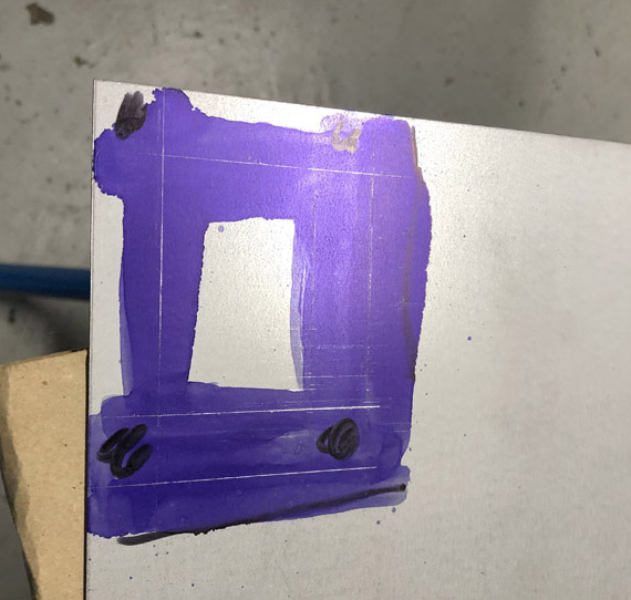 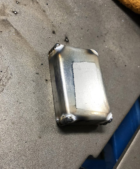 Then, I tacked the box in place on the bracket, making sure the nut plate is both inside the box and could still move around: 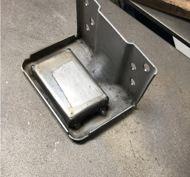 I only tacked it because the box has no structural purpose, and I sealed around it with seam sealer. Then, I fitted the bracket in place, using long screws with extra nuts to hold the bracket in place for welding:  Here's what it looks like all done: 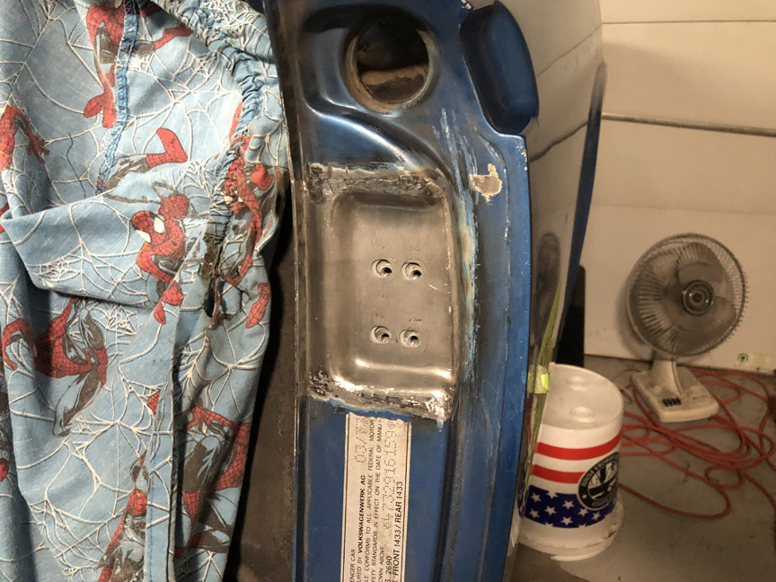 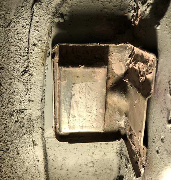 |
|
|
|
| BillC |
Feb 9 2021, 04:50 PM
Post
#110
|
|
Senior Member Group: Members Posts: 732 Joined: 24-April 15 From: Silver Spring, MD Member No.: 18,667 Region Association: MidAtlantic Region |
Next step is to replace the rot under the jack point, which looks like this:
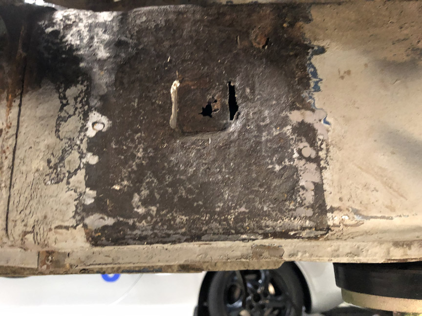 Unfortunately, from this angle it's hard to see the shallow pyramid shape formed into the factory metal, but it's there. That shape is why I'm making a pattern before cutting metal First step is to make a pattern, using masking tape: 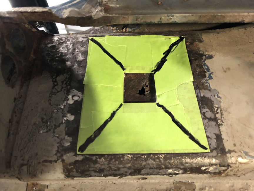 The tape conforms to the pyramid-like shape of the original metal, so I can transfer the pattern to new, flat metal (after cutting the pattern open). 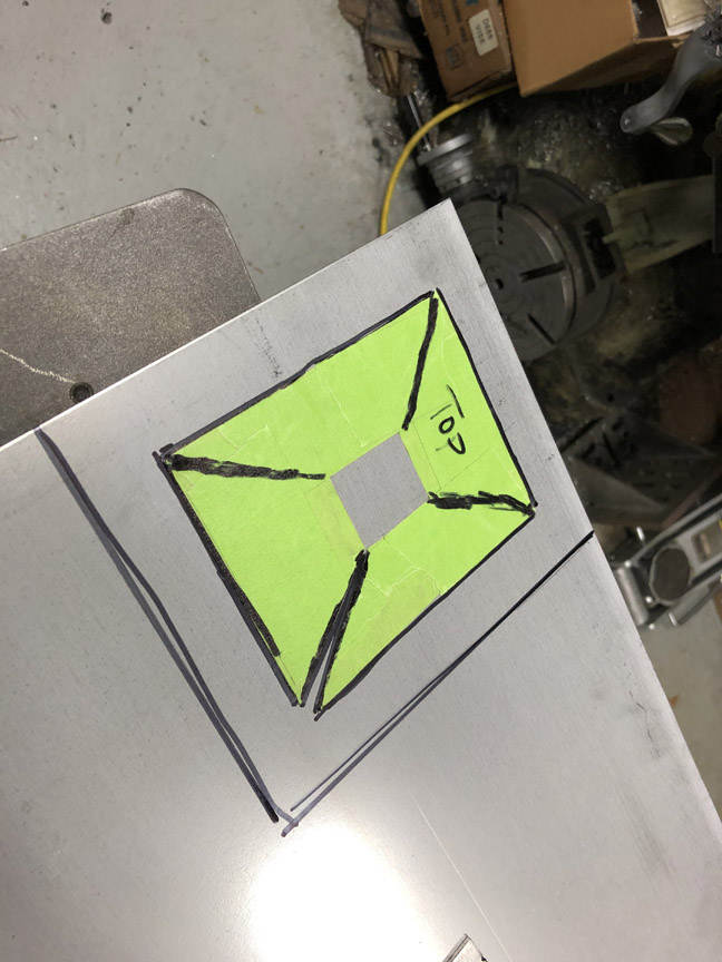 After cutting out the piece of sheet metal (.071" galvaneal from McMaster-Carr), I set up a set of clamps on the mill as a mini pan brake: 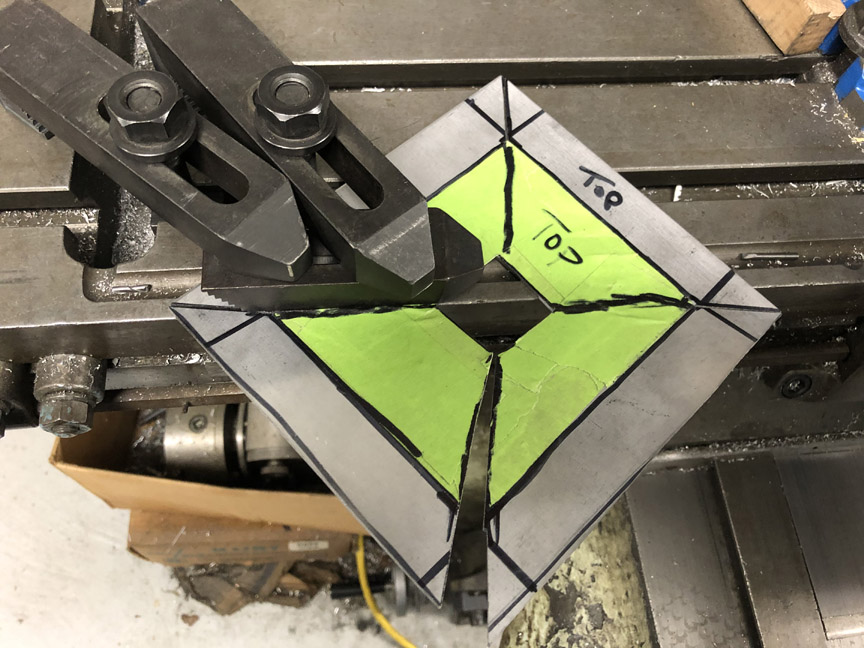 Here's what the metal looks like bent to shape, and then welded: 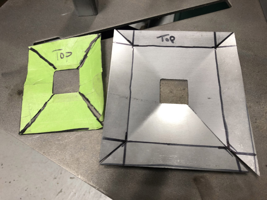 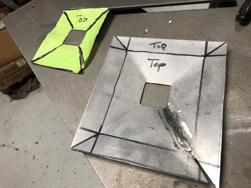 As you may have noticed, I made the part oversize, because I haven't cut out the original metal yet and don't know what I'll find underneath -- at this stage, it's easier to remove extra metal once I know the hole size than to have to add it later. Also, the center "socket" will be another piece formed to match the replacement jack tube and then welded to the backside of this piece. |
|
|
|
| Front yard mechanic |
Feb 9 2021, 08:41 PM
Post
#111
|
|
Senior Member Group: Members Posts: 1,451 Joined: 23-July 15 From: New Mexico Member No.: 18,984 Region Association: None |
I think I know what you will find (IMG:style_emoticons/default/welder.gif)
|
|
|
|
| BillC |
Feb 13 2021, 02:03 PM
Post
#112
|
|
Senior Member Group: Members Posts: 732 Joined: 24-April 15 From: Silver Spring, MD Member No.: 18,667 Region Association: MidAtlantic Region |
QUOTE(Front yard mechanic @ Feb 9 2021, 09:41 PM) Yeah, I suppose you just might at that. (IMG:style_emoticons/default/idea.gif) (IMG:style_emoticons/default/biggrin.gif) ------------------------------------------------------------ Now it's time to make the recessed center pocket for the jack post. First steps were to cut out a blank from the same sheet metal and then bend it to shape: 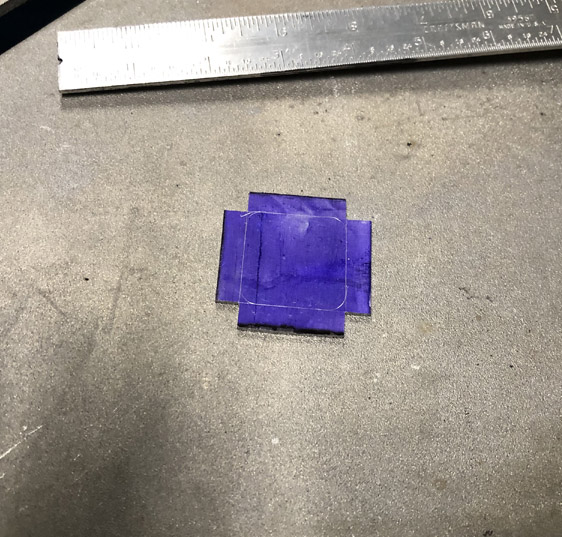 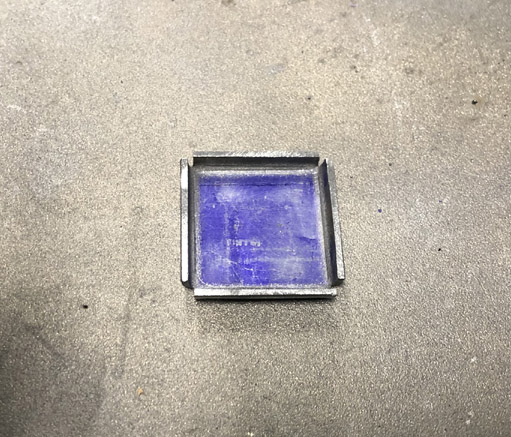 Then, the pocket is held in place with magnets and welded: 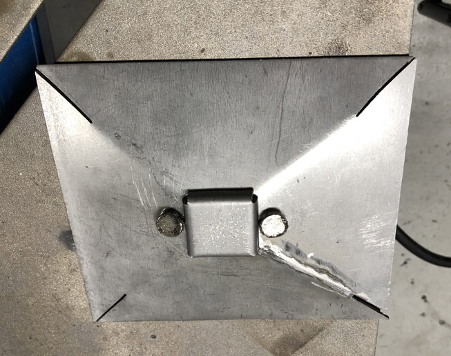 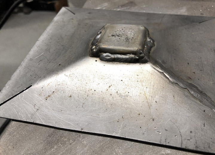 Then, the pocked is cleaned up on the face, and the post is put in place. The post is just dropped in for now, to make sure it will fit later for final fitting and welding. 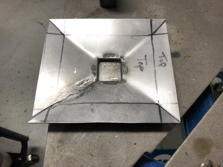 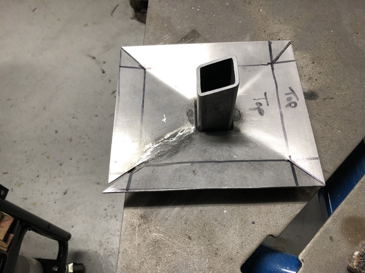 |
|
|
|
| Eric_Shea |
Feb 13 2021, 02:05 PM
Post
#113
|
|
PMB Performance Group: Admin Posts: 19,304 Joined: 3-September 03 From: Salt Lake City, UT Member No.: 1,110 Region Association: Rocky Mountains |
RD needs to make that latch box. Not fun. Good work (IMG:style_emoticons/default/smilie_pokal.gif)
|
|
|
|
| BillC |
Feb 13 2021, 05:50 PM
Post
#114
|
|
Senior Member Group: Members Posts: 732 Joined: 24-April 15 From: Silver Spring, MD Member No.: 18,667 Region Association: MidAtlantic Region |
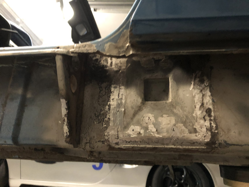
Every so often, this car gives me a pleasant surprise. I cut out the jackpoint "pyramid", and this is what it looks like underneath:
 |
|
|
|
| Front yard mechanic |
Feb 13 2021, 08:57 PM
Post
#115
|
|
Senior Member Group: Members Posts: 1,451 Joined: 23-July 15 From: New Mexico Member No.: 18,984 Region Association: None |
Sweet (IMG:style_emoticons/default/beer.gif)
|
|
|
|
| Montreal914 |
Feb 13 2021, 11:46 PM
Post
#116
|
|
Advanced Member Group: Members Posts: 2,135 Joined: 8-August 10 From: Claremont, CA Member No.: 12,023 Region Association: Southern California |
Very nice find in the long. (IMG:style_emoticons/default/smile.gif)
Looks like your pyramid will fit perfectly! With such precise CAD work, not surprising (IMG:style_emoticons/default/sunglasses.gif) |
|
|
|
| BillC |
Feb 17 2021, 07:57 PM
Post
#117
|
|
Senior Member Group: Members Posts: 732 Joined: 24-April 15 From: Silver Spring, MD Member No.: 18,667 Region Association: MidAtlantic Region |
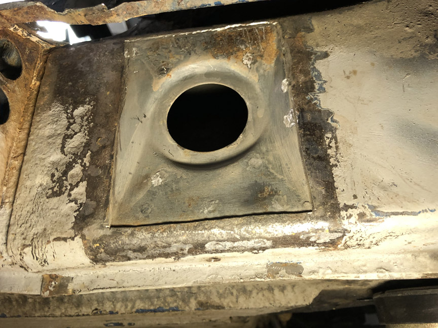
Had some free time this afternoon to finish welding and grinding the inner pyramid replacement. Doesn't look too horrible:
 Next steps will be to fit the jackpoint tube and the outer pyramid. Both of these are replacements from RD, so that should go faster. |
|
|
|
| seanpaulmc |
Feb 18 2021, 08:01 PM
Post
#118
|
|
Member Group: Members Posts: 452 Joined: 6-December 16 From: Orlando, FL Member No.: 20,649 Region Association: South East States |
QUOTE(BillC @ Feb 17 2021, 08:57 PM) Had some free time this afternoon to finish welding and grinding the inner pyramid replacement. Doesn't look too horrible: Next steps will be to fit the jackpoint tube and the outer pyramid. Both of these are replacements from RD, so that should go faster. Very nice work! Please keep it going. (IMG:style_emoticons/default/welder.gif) I need this play by play for referencing. (IMG:style_emoticons/default/pray.gif) The fender does not look to be cut. When putting the jack receiver and plate back in how will you weld in the top portion? Thanks, Sean |
|
|
|
| BillC |
Feb 20 2021, 05:58 PM
Post
#119
|
|
Senior Member Group: Members Posts: 732 Joined: 24-April 15 From: Silver Spring, MD Member No.: 18,667 Region Association: MidAtlantic Region |
QUOTE(seanpaulmc @ Feb 18 2021, 09:01 PM) The fender does not look to be cut. When putting the jack receiver and plate back in how will you weld in the top portion? The rear quarter isn't cut. I'm trying to minimize the amount of sheet metal I have to cut to get to the sheet metal that needs to be fixed. Just like the passenger side (see page 5), I did the top welds through the rear wheel opening inside the rear quarter -- I added a pic of this at the bottom of this update. ---------------------------------------------------------------------------------------------- And on to the next steps: First step was to install the jackpoint tube. Before I cut out the old tube, I took careful measurements to make sure the new tube ended up in the same position. So, once the new inner pyramid was in, I started fitting the new tube. I held it in place and put a single tack weld. Then, I moved the tube to position and added two more tacks. Unfortunately for me, the tube moved a little while tacking and I had to cut the tacks, reposition the tube and re-tack it. Second time got it right, so I welded it all up. Then I painted the entire area under the outer pyramid with high-zinc paint. Here's how that came out: 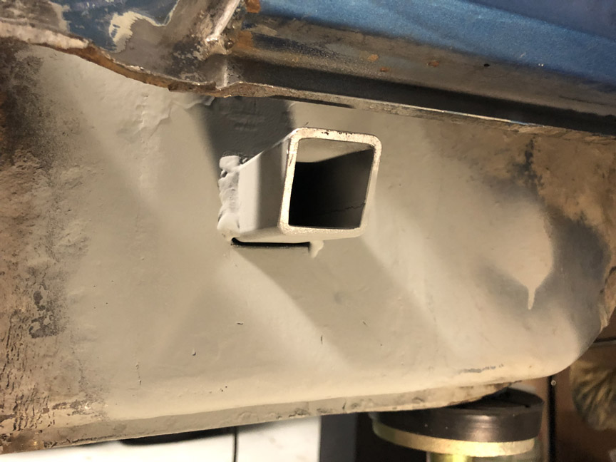 While I was waiting for the paint to dry, I prepared the outer pyramid part. This consisted of punching out twenty 1/4" holes along the perimeter and then drilling two 3/8" drain/vent holes near the bottom. Here's how that looked: 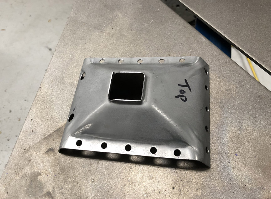 Once the paint dried, I tried fitting the new outer pyramid. But, unlike the passenger side, this side wouldn't quite fit without modification. I used the dremel tool to cut two little slices, to tweak the upper lip out enough to clear the post: 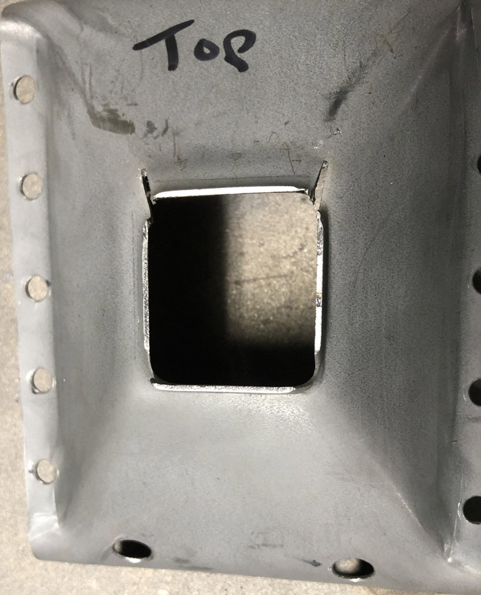 Here's what the pyramid looked like when fitted into place, with "fuzzy" magnets holding it in place: 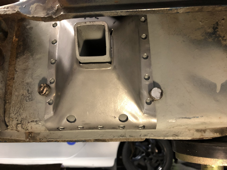 I then plug-welded the mounting holes. Then, I used an old cold chisel and a hammer to close the opening around the jackpoint tube, and then welded that up too. Finally, I ground down the plug welds with the little belt sander. 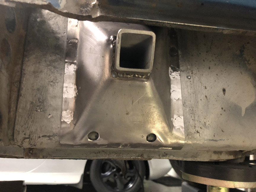 And, since someone asked, I welded up the three rear top plug welds inside the rear quarter, through the rear wheel opening. It's very tight in there, and it was a real PITA, but it's better then cutting the quarter open. 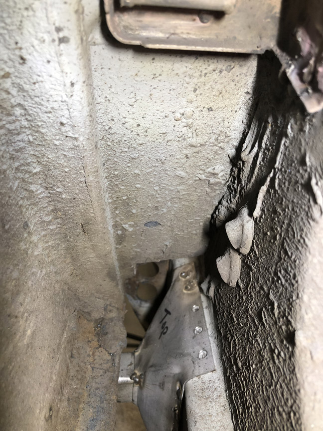 I got the front two plug welds through the hole cut in the door sill. That hole was cut because of the rust holes in the corner. Otherwise, I would have had to do all five holes through the quarter, like the passenger side. |
|
|
|
| BillC |
Feb 22 2021, 08:17 PM
Post
#120
|
|
Senior Member Group: Members Posts: 732 Joined: 24-April 15 From: Silver Spring, MD Member No.: 18,667 Region Association: MidAtlantic Region |
Managed to sneak in some time on the car last night and tonight.
Time to patch what appears to be the last big hole on the car, at the bottom of the door opening: 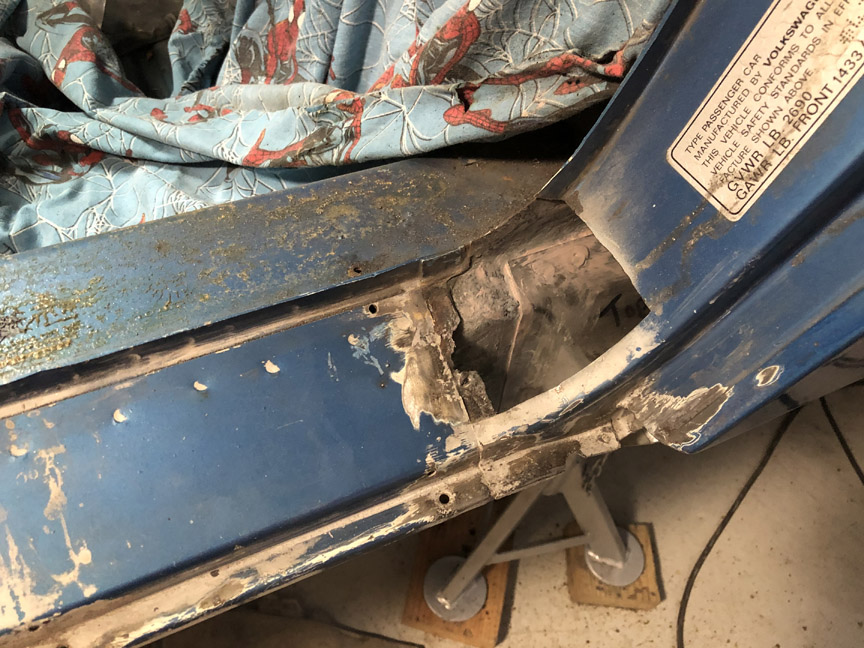 This will get two separate patches, one on the bottom and one for the curve. Here's the bottom patch fitted: 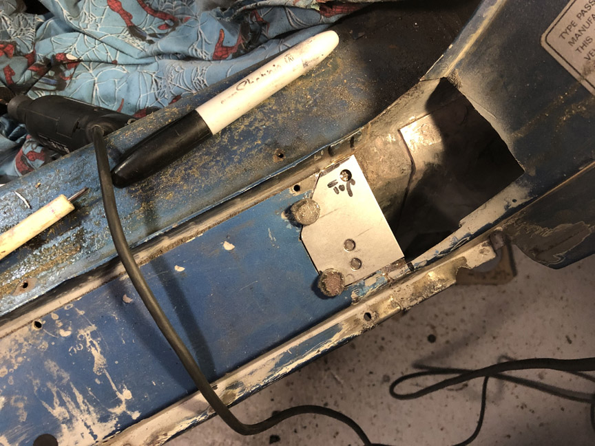 And then welded in and ground down: 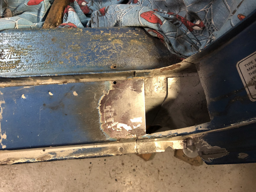 Last thing I was able to do before having to call it a night was to fit the second patch: 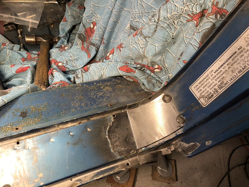 I'm hoping to be able to finish the second patch before the weekend. |
|
|
|
|
2 User(s) are reading this topic (2 Guests and 0 Anonymous Users)
0 Members:

|
Lo-Fi Version | Time is now: 14th June 2026 - 07:22 PM |
Invision Power Board
v9.1.4 © 2026 IPS, Inc.