|
|
|
Porsche, and the Porsche crest are registered trademarks of Dr. Ing. h.c. F. Porsche AG.
This site is not affiliated with Porsche in any way. Its only purpose is to provide an online forum for car enthusiasts. All other trademarks are property of their respective owners. |
|
|

  |

| JRust |
 Jul 6 2020, 08:40 PM Jul 6 2020, 08:40 PM
Post
#21
|
|
914 Guru  Group: Members Posts: 6,317 Joined: 10-January 03 From: Albany Oregon Member No.: 129 Region Association: Pacific Northwest |
Looks great Kent! Love to see the step by step there
|
   |

 
|
| 2mAn |
Jul 6 2020, 09:02 PM
Post
#22
|
|
trying to see how long I can go without a 914 Group: Members Posts: 502 Joined: 14-November 13 From: Westchester (Los Angeles) Member No.: 16,644 Region Association: Southern California |
Love it. I could hear the garage cursing because I’m usually yelling at that same a$$hole lol
|
|
|
|
| 76-914 |
Jul 6 2020, 09:51 PM
Post
#23
|
|
Repeat Offender & Resident Subaru Antagonist Group: Members Posts: 13,896 Joined: 23-January 09 From: Temecula, CA Member No.: 9,964 Region Association: Southern California |
QUOTE(808 WRX @ Jul 6 2020, 12:39 PM)  QUOTE(76-914 @ Jul 3 2020, 05:24 PM) Once it's is secure be sure the section past or to the rear of the arc is perpendicular or 90 deg to the floor and that the long end is level or parallel to the floor. Ultimately the top of the tube should be 1" below the bottom of the angle iron bracket. This IS important. You may find you need to cut that angle piece twice in order to raise the back end enough to get it level while maintaining the 1" gap mentioned above and keeping the length level. Now is the time to mark the compound angle that will be trimmed off the top end. The 1st cradle I used a marks-a-lot but found the hacksaw blade to be much more accurate in transferring the mark because the blade could be held flush against both sides of the tape roll. Hold the roll flush against the plate. I needed to stretch the roll into an over same to work around the protruding bolts. I am probably a month or two from building myself a cradle. So your timing is perfect and I am looking forward to this thread! Quick question, why is the 1" gap important? Two reasons. I didn't flip the throttle body and this leaves enough room between the top of the throttle body and the trunk bulkhead so that the steel fuel lines can pass over unimpeded. Look at my build thread on the black '73 and you'll see better than I can explain. It's in the Member Build Threads section, very top. Perhaps more importantly is ground clearance. I measured 5 1/2" from the ground to the windage flaps attached at the bottom of the firewall. I don't use those flaps but I thought clearance that was a good height to place the bottom of the engine. It was the lowest point on the car and I didn't want to exceed that. (IMG:style_emoticons/default/beerchug.gif) |
|
|
|
| 76-914 |
Jul 6 2020, 10:04 PM
Post
#24
|
|
Repeat Offender & Resident Subaru Antagonist Group: Members Posts: 13,896 Joined: 23-January 09 From: Temecula, CA Member No.: 9,964 Region Association: Southern California |
QUOTE(Andyrew @ Jul 6 2020, 12:45 PM) (IMG:style_emoticons/default/smilie_pokal.gif) (IMG:style_emoticons/default/popcorn[1].gif) (IMG:style_emoticons/default/welder.gif) Awesome!!! QUOTE(tygaboy @ Jul 6 2020, 01:24 PM) QUOTE(Andyrew @ Jul 6 2020, 12:45 PM) (IMG:style_emoticons/default/smilie_pokal.gif) (IMG:style_emoticons/default/popcorn[1].gif) (IMG:style_emoticons/default/welder.gif) Awesome!!! (IMG:style_emoticons/default/agree.gif) (IMG:style_emoticons/default/agree.gif) (IMG:style_emoticons/default/agree.gif) (IMG:style_emoticons/default/smilie_pokal.gif) QUOTE(914forme @ Jul 6 2020, 01:32 PM) Love the low tech cradle build. The roll of tape and hack saw blade trick genius. I would have used machinist dye, but that is me getting all fancy. (IMG:style_emoticons/default/whip[1].gif) back to the day job for me QUOTE(JRust @ Jul 6 2020, 07:40 PM) Looks great Kent! Love to see the step by step there Just wanted to say thanks. Coming from you guys is the best. Stephen, I miss you presence. I've learned of the dye and center punches from you. Game changers! I looked over my last build and was horrified to see I didn't respond to many comments. How rude of me. I get tunnel vision during builds and overlook things like this. I promised myself that I'd respond to all this time. No matter how busy I may believe I am. I'll be awhile before continuing the cradle as I'm awaiting some bushing stock which I used to buy locally. Should be here next week. So today I got the engine upon the stand so I can start putting some of those cut and drilled pieces together that form the motor mounts. To be continued......... |
|
|
|
| andys |
Jul 7 2020, 11:24 AM
Post
#25
|
|
Advanced Member Group: Members Posts: 2,165 Joined: 21-May 03 From: Valencia, CA Member No.: 721 Region Association: None |
This is what I did for my cradle in case it helps. Different trans, different motor, but it's a cradle nevertheless. I paid a hotrod shop to make the bends.
Andys Attached thumbnail(s) 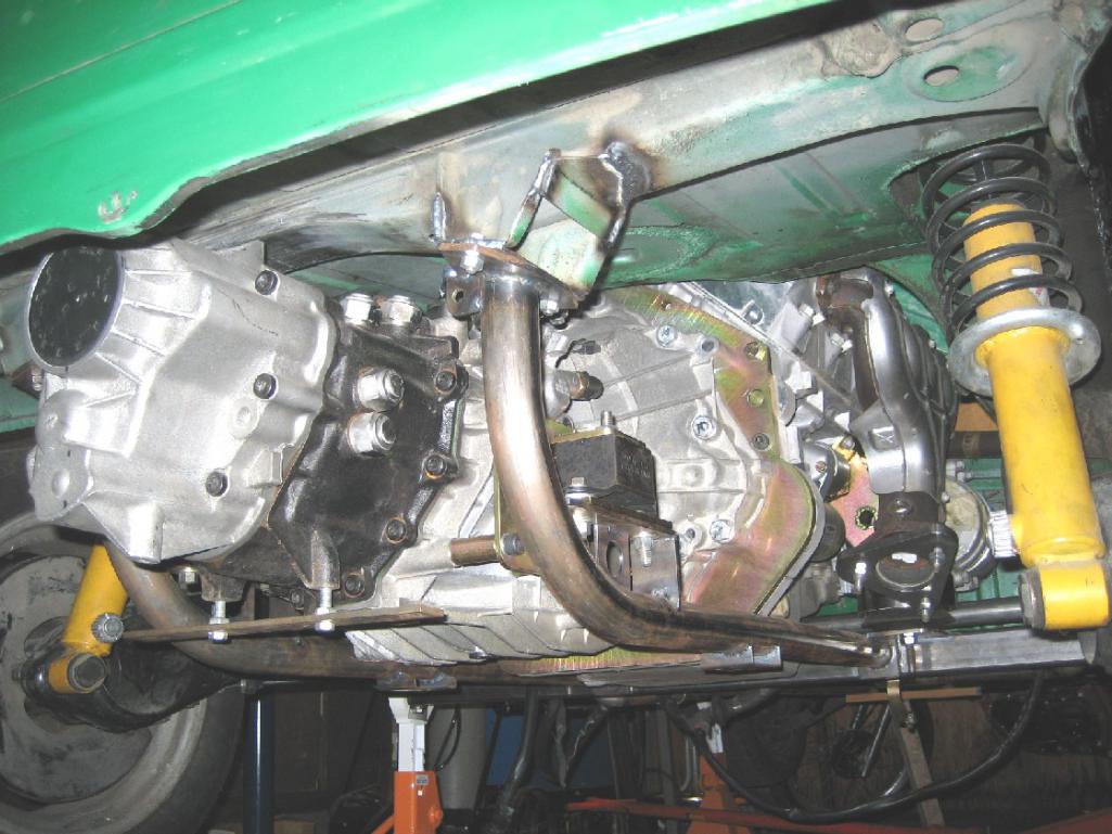
|
|
|
|
| 76-914 |
Jul 7 2020, 12:59 PM
Post
#26
|
|
Repeat Offender & Resident Subaru Antagonist Group: Members Posts: 13,896 Joined: 23-January 09 From: Temecula, CA Member No.: 9,964 Region Association: Southern California |
QUOTE(andys @ Jul 7 2020, 10:24 AM) This is what I did for my cradle in case it helps. Different trans, different motor, but it's a cradle nevertheless. I paid a hotrod shop to make the bends. Andys That is very nice. This is my 2nd one and I’m just documenting in case some one wants to build their own and save $600-$800. What’s different about mine is it has detachable casters that allows me to roll the drive train in and out. Thank and it is very light. (IMG:style_emoticons/default/beerchug.gif) |
|
|
|
| 76-914 |
Jul 7 2020, 09:38 PM
Post
#27
|
|
Repeat Offender & Resident Subaru Antagonist Group: Members Posts: 13,896 Joined: 23-January 09 From: Temecula, CA Member No.: 9,964 Region Association: Southern California |
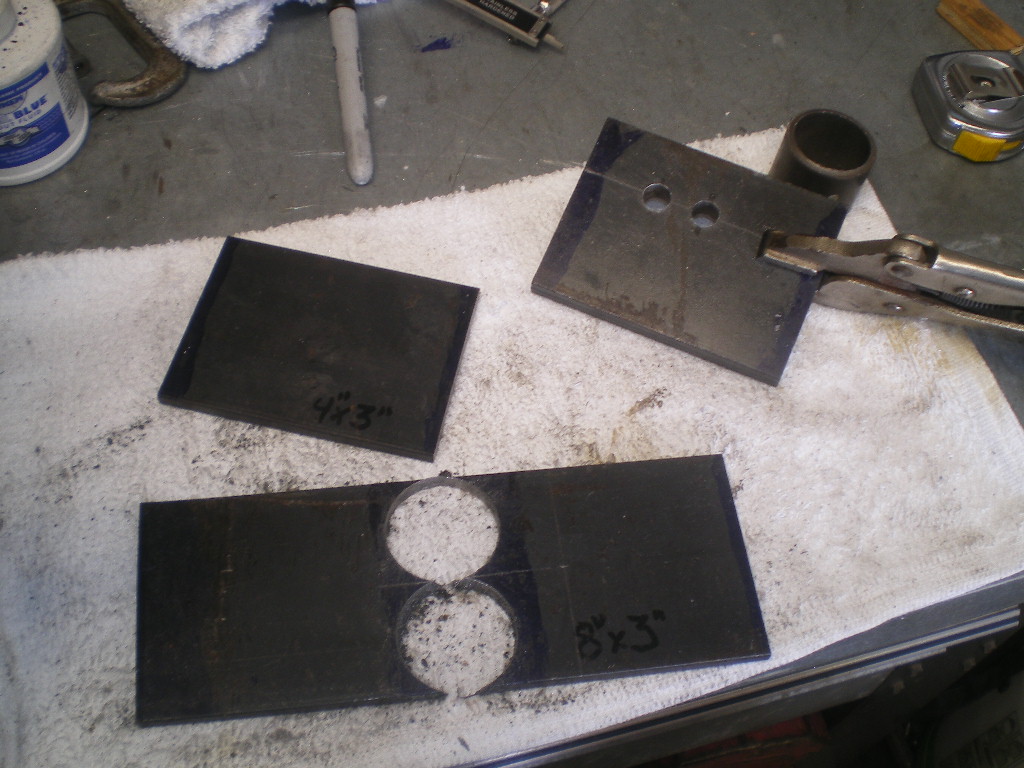
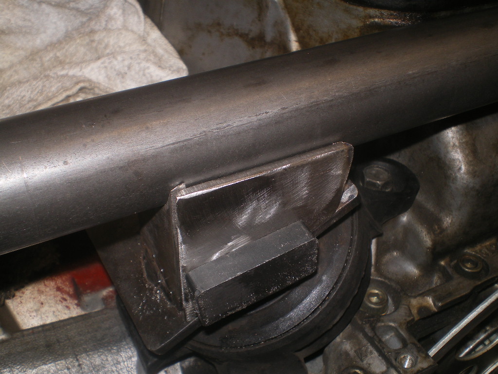
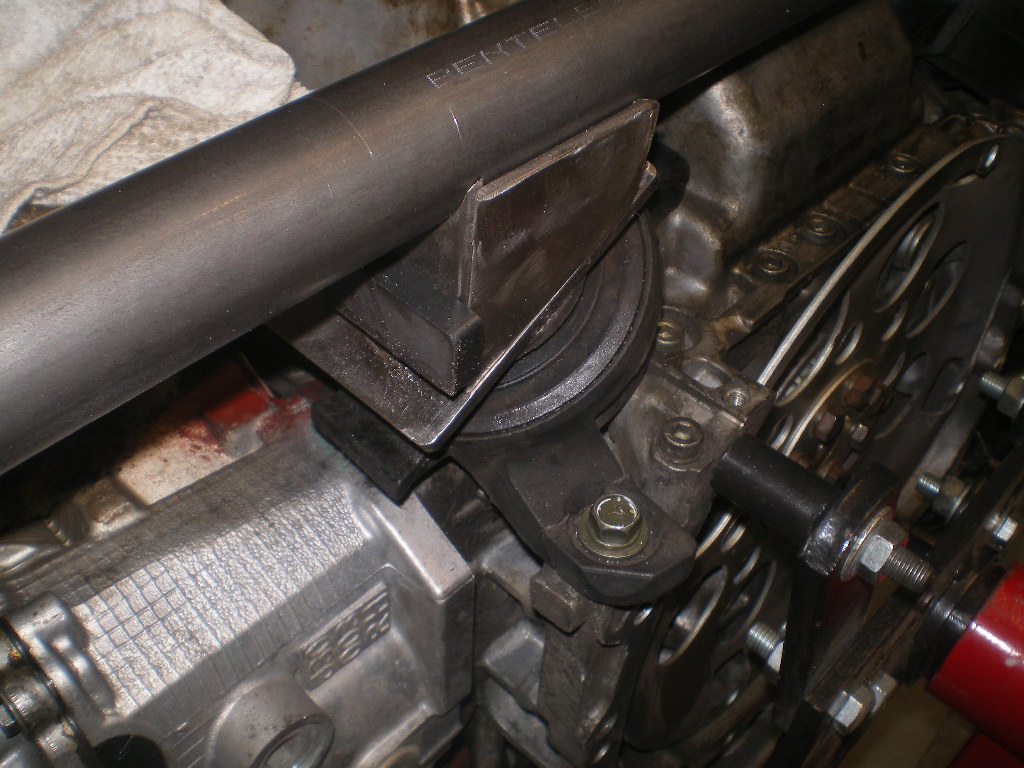
Round 4; I was able to steal away for 2 hours this afternoon so I began assembly of the hard mounts themselves. Remember these pieces? It's time to use some of them.
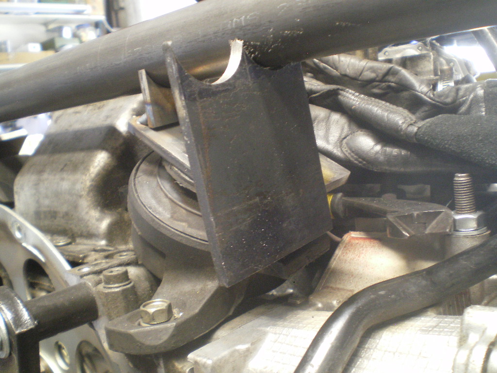
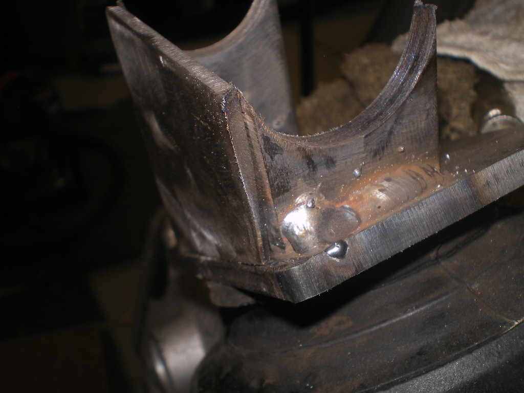
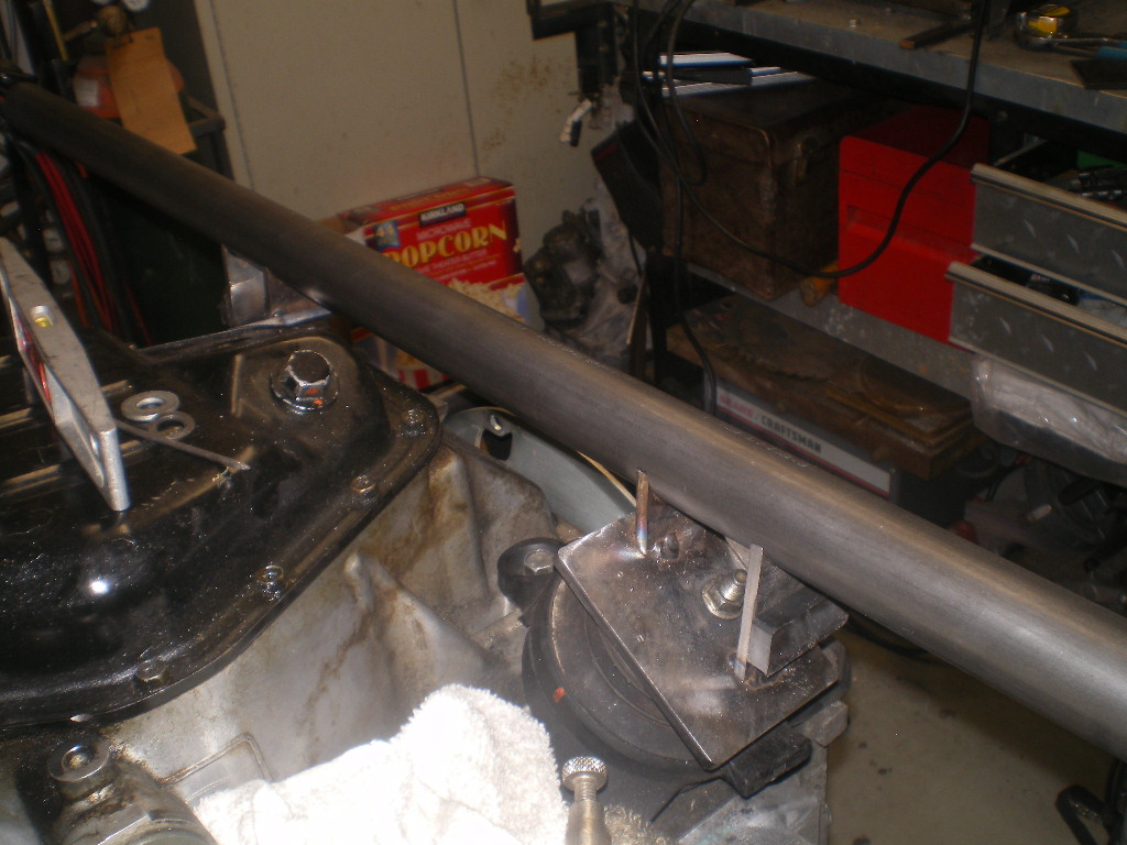
 First I rotate the engine so it's bottom side up with the factory rubber mounts installed. Then level it. If you've a cheap HF engine stand like mine you'll do well to check for level often. I placed the angle finder on the oil pan and also the engine case to confirm the oil pan was not out of whack. The afternoon sun was glaring in case you're wondering about the popcorn box. 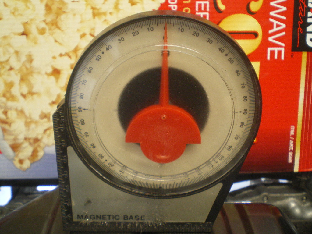 Next attach the 4x3 plates that were drilled to match the rubber mounts. Now take one side of the plate that was drilled with 2-1.5" holes and split it between the holes. Now you have 2 pieces that have 2 "U's" if you will. Take one of those measure down 3/4" from the lowest point of the "U" and cut it down to size. After this you can split this piece down the middle. You now have 2-1.5" wide "U' tabs that are appx 1.5" tall @ the highest point and 3/4" tall if you measure to the bottom of the "U". These are the short inner pieces that will support the cross bar. There will be 2 longer pieces and they will tie into the shorter pieces w/ some 3/16" but I'm getting ahead of myself. Looking at the 1st pic below you will see I used some magnets to support these short "U" shaped tabs. I located the tabs so they line up with one edge of the rubber mount so the support is above the mount and not past it. I didn't want the load outside the area of the mount. I used a finish nail to hold the tab vertical. The tab is placed 3/16" away from the edge of the 4x3 plate to allow for the piece of 3/16" I mentioned above. 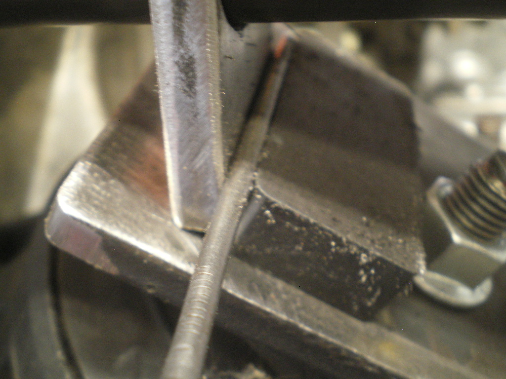 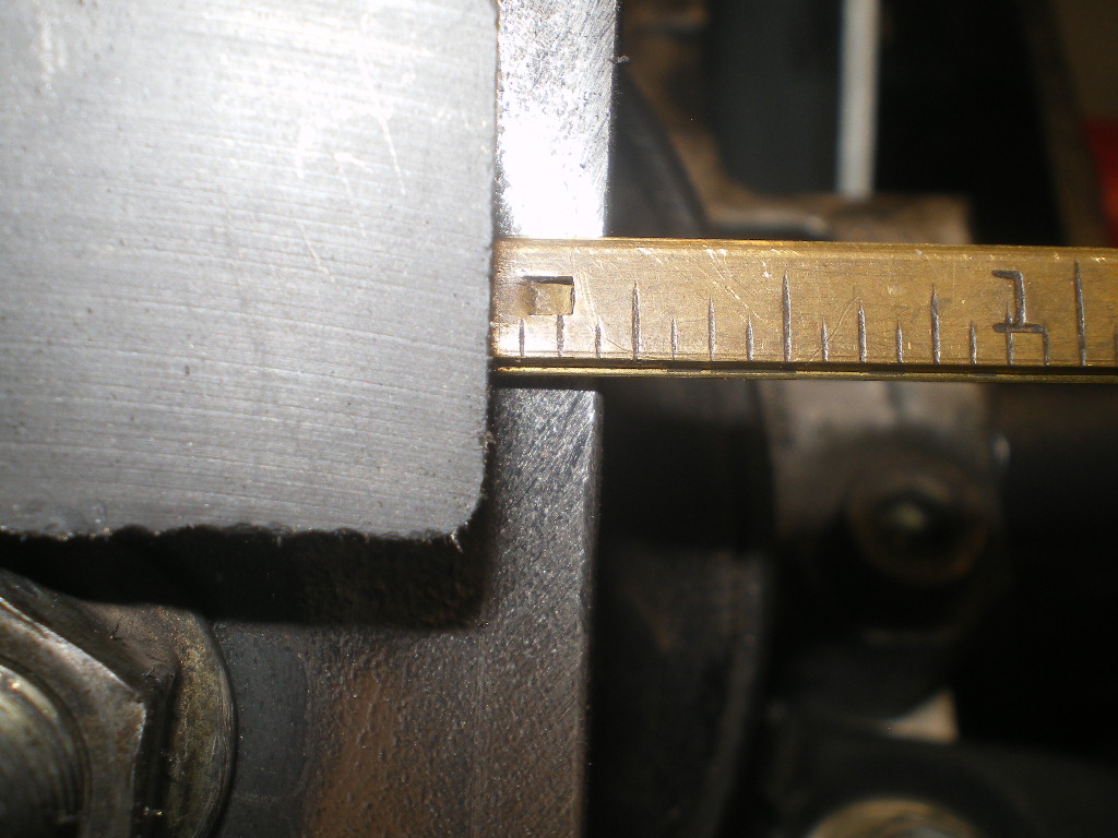 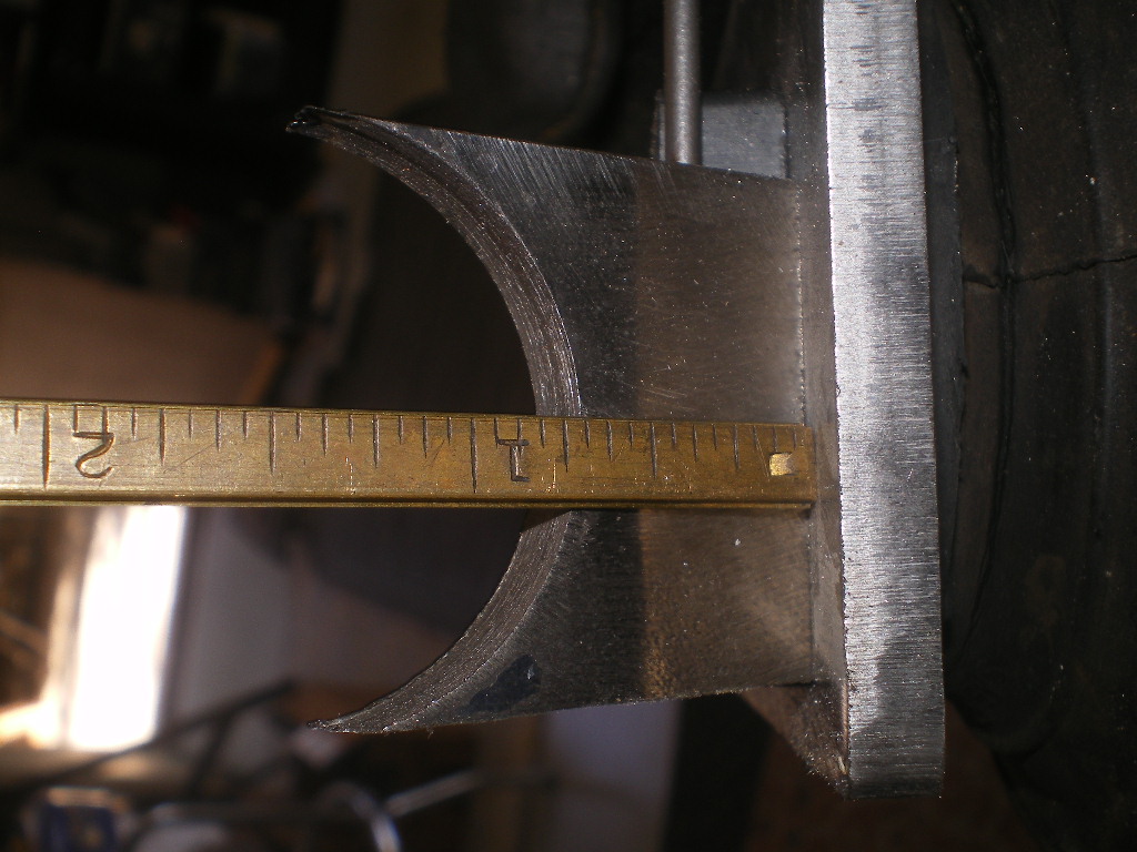 I repeated this step on the other side but when I place the crossbar in the tabs the left side was slightly higher than the right one. This can be expected unless your making these tabs on a mill. 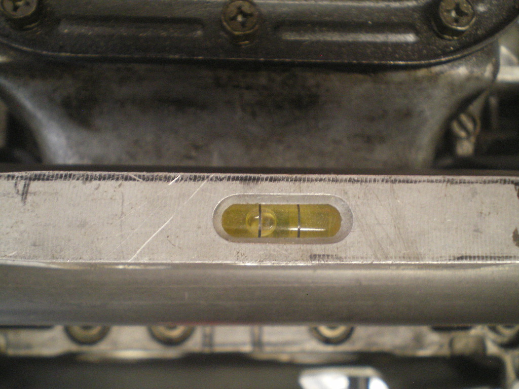 But the fix is simple. I ground this tab with a slight angle and lowered the nail a hair which brought the bar back to level. 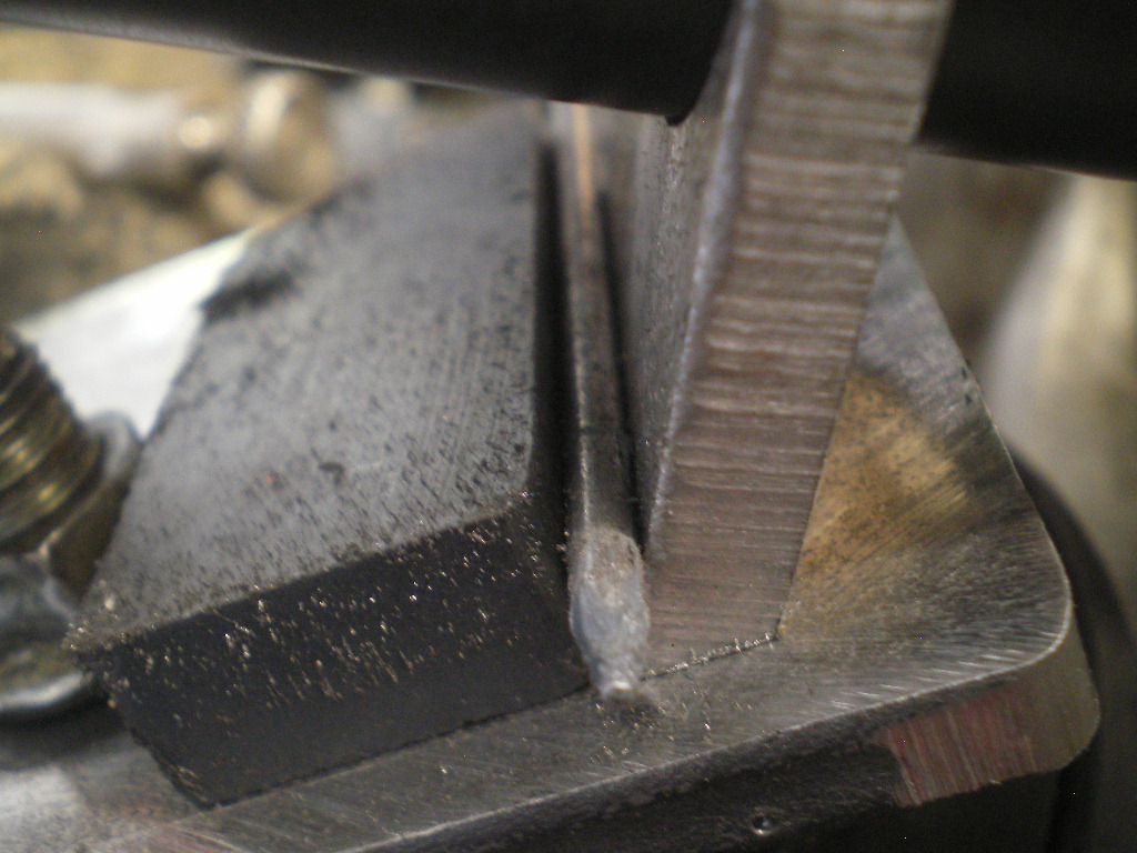 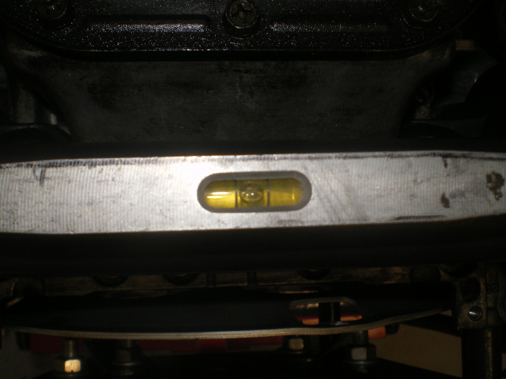 Next check for level at the engine and crossbar then a couple of spot welds and check for level again. 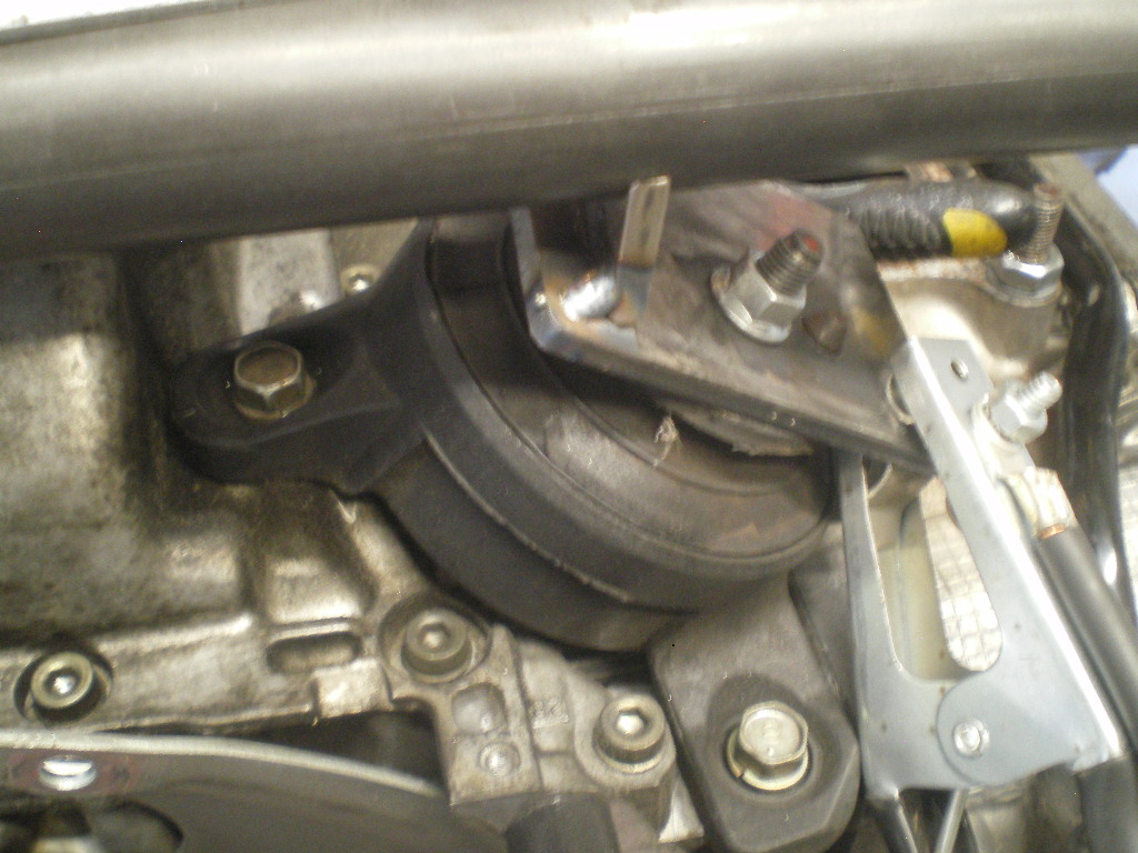 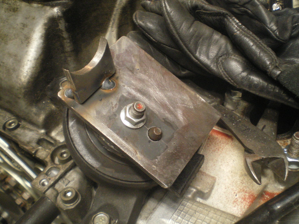 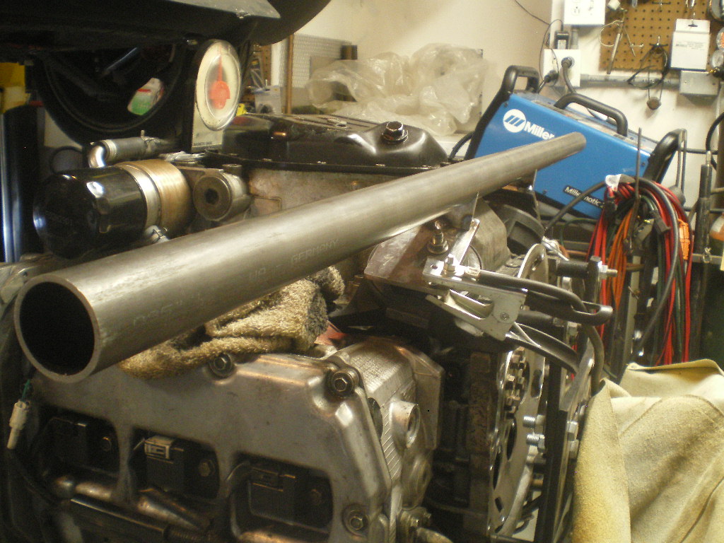 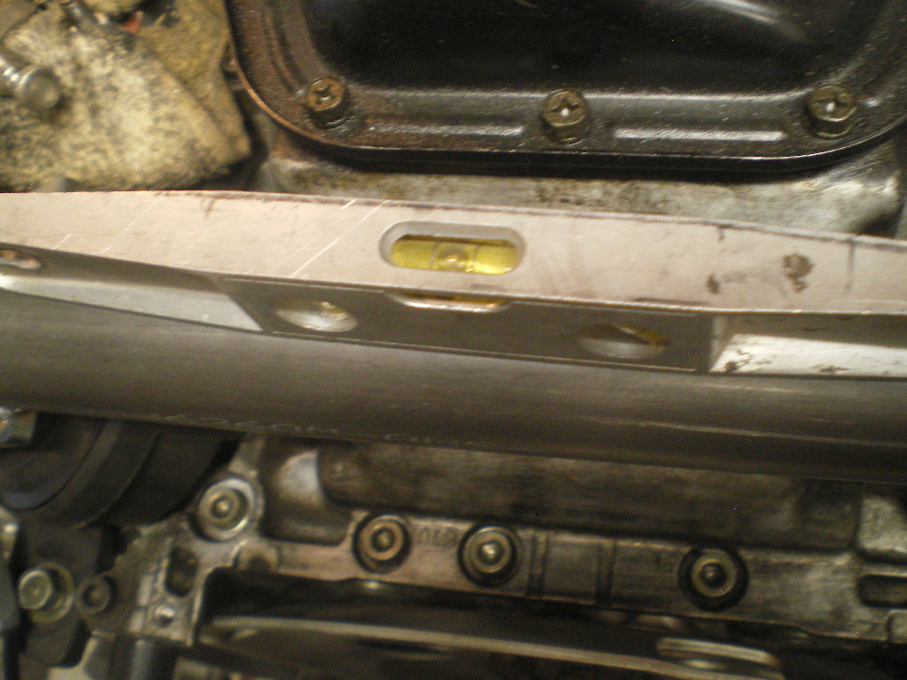 to be continued................. |
|
|
|
| 76-914 |
Jul 8 2020, 03:29 PM
Post
#28
|
|
Repeat Offender & Resident Subaru Antagonist Group: Members Posts: 13,896 Joined: 23-January 09 From: Temecula, CA Member No.: 9,964 Region Association: Southern California |
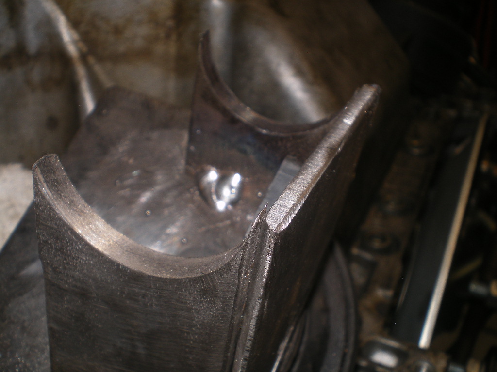
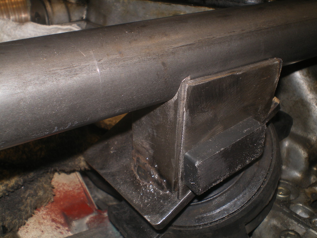
OK, things are fixing to get wordy so bare with me. In this next part we are going to cut the longer U tabs to length, tack them in place then cut the piece that will eventually tie the U tabs together. I'm going to throw a lot of pics at you in hopes it will answer any unanswered questions. If your long U tabs don't end up exactly like mine, so be it. What is important here is that all four U tabs contact the crossbar and the crossbar remains level, i.e. square to the engine. Other than that it's just aesthetics. In this 1st pic the piece isn't split vertically yet because we're determining where to cut it. And both pieces should be the same length. Again I use magnets to hold the pieces. If you don't see it, it is on the other side.
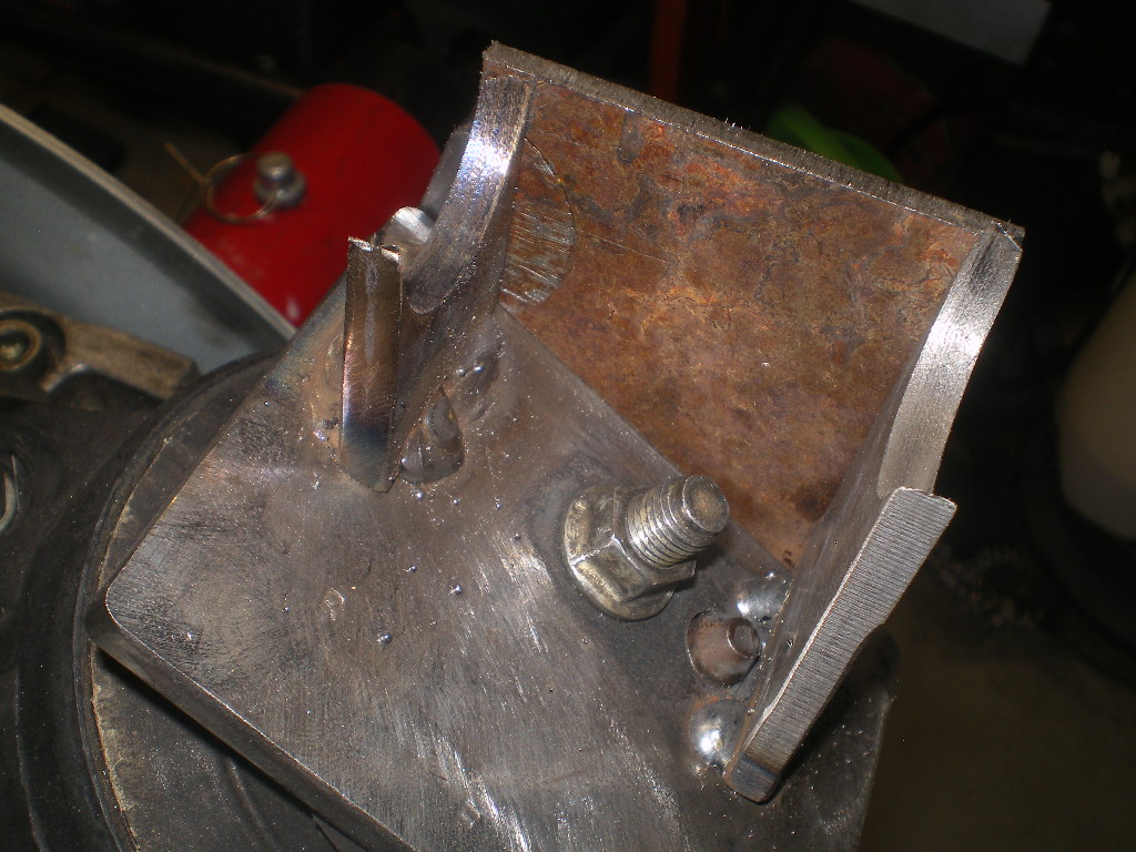
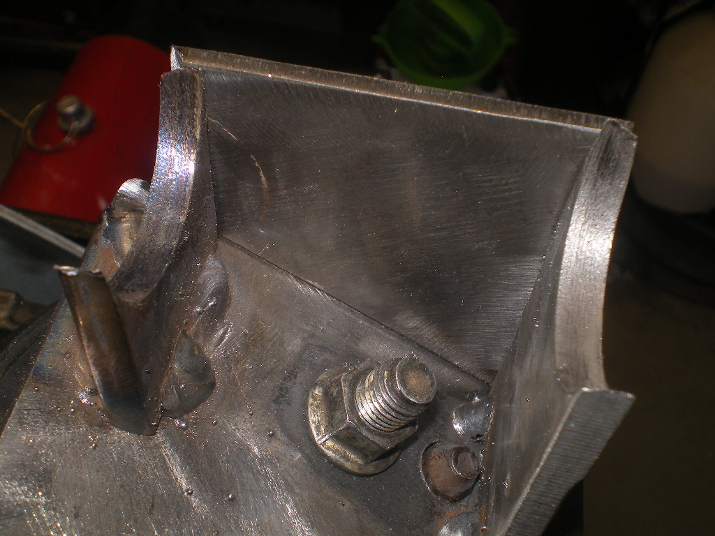
 [attachmentid=752025 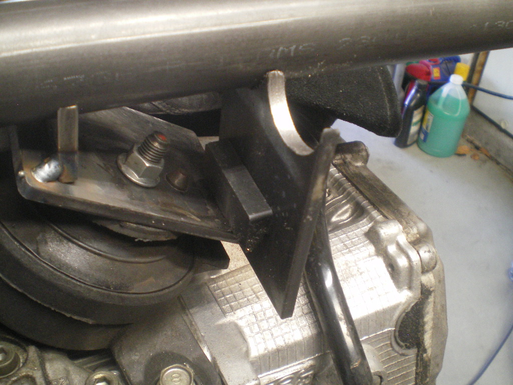 This is how I determined the height. The flat of this caliper happened to be the correct width so this is what I used to determine the cut line or height of the U tab. I held it level and at the spot I want the inner edge of the U tab to be then marked the tab and the caliper. LOL. It's a cheap tool anyway. 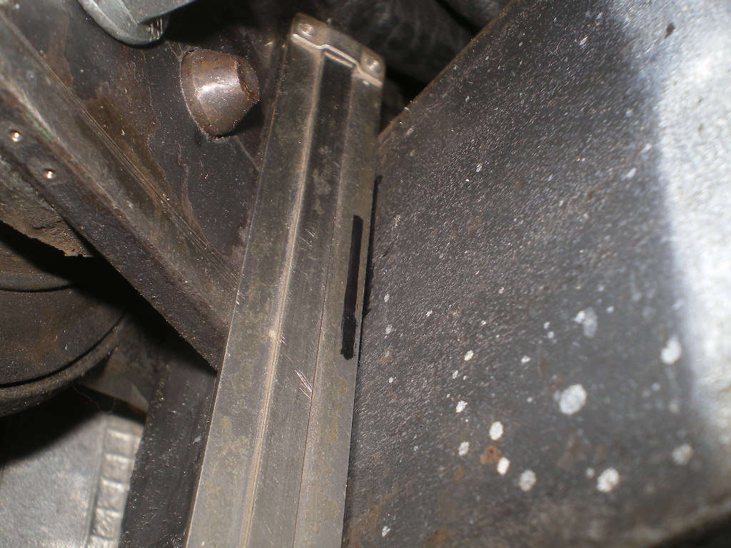 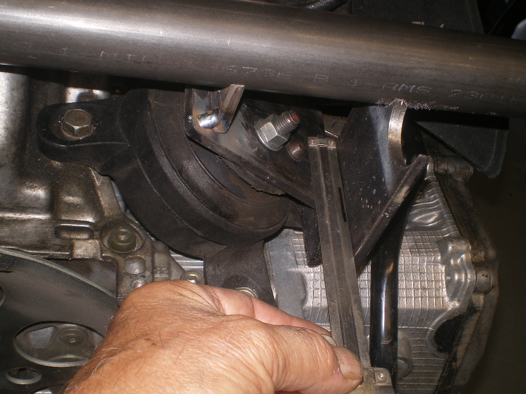 Then I cut it on the mark and split the piece giving me 2 equal length U tabs. The same process was used for the shorter U tabs. 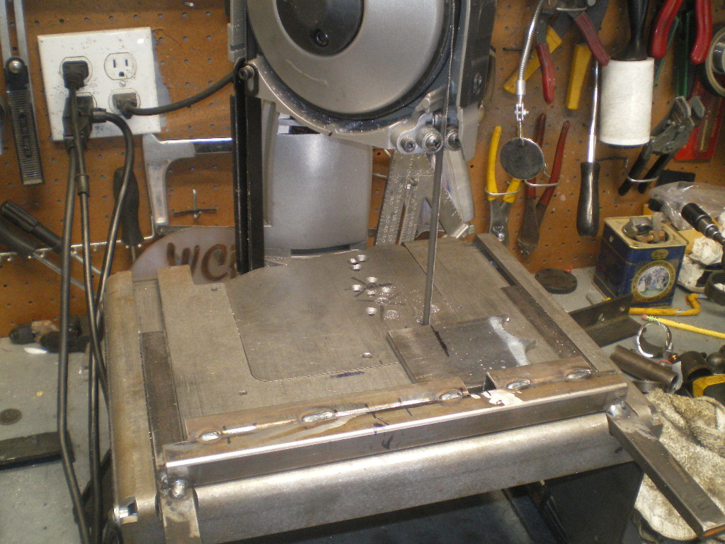 Now with the crossbar sitting in the 2 tacked U tabs position the longer tabs so they contact the bar and plate. Don't get it too close to the nut that you will need to wrench on later. Other than that it won't matter the exact location. Or whether it is square with the other tabs. Once these are positioned go ahead and tack them in place. We're not tacking the crossbar in place yet. That's the next to last step. 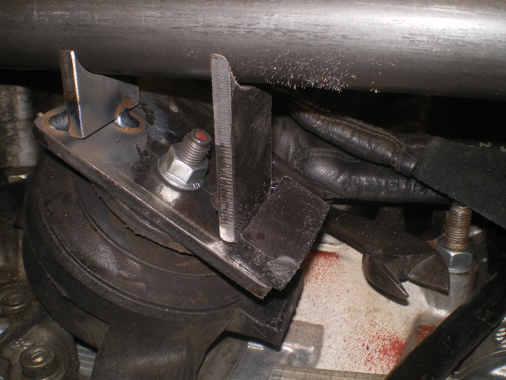 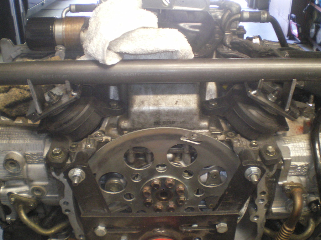 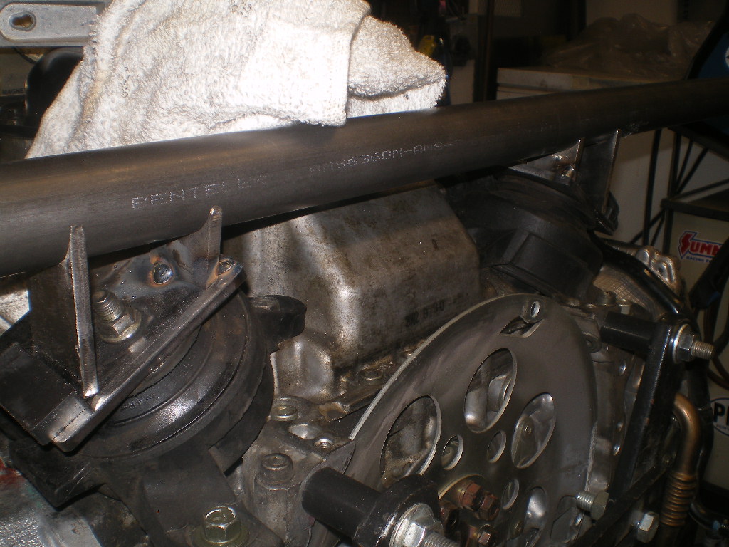 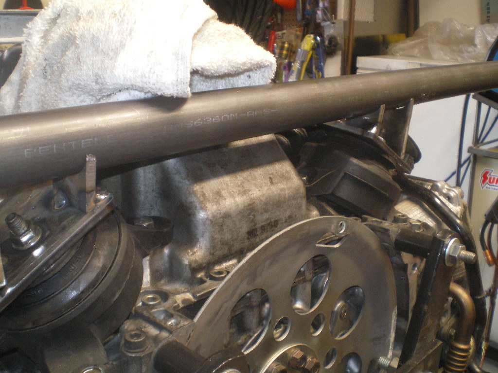 Remove the bar and mounts from the engine and complete welding the tabs to the plate. Avoid getting any buildup in that 3/16" area or you'll need to bring it down. 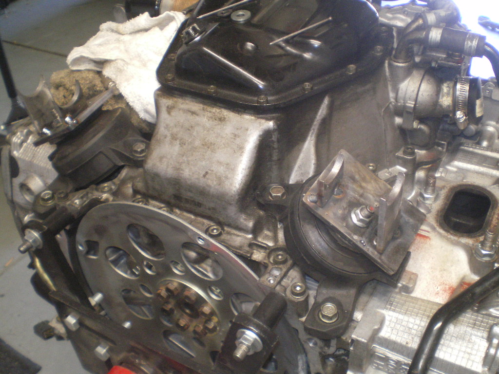 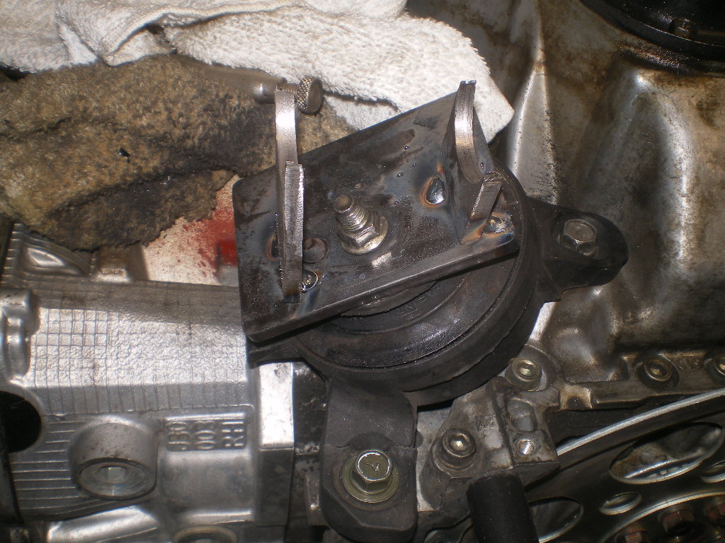 I forgot to mention to check that the crossbar still contacts all 4 tabs and is level before completing the welds on the tabs. (IMG:style_emoticons/default/headbang.gif)  And while I'm at it I should mention that these dimples on the backside of the plates are to allow a flush fit with the mount since there are these protruding rivet heads. 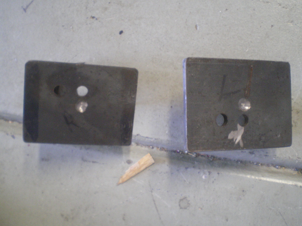 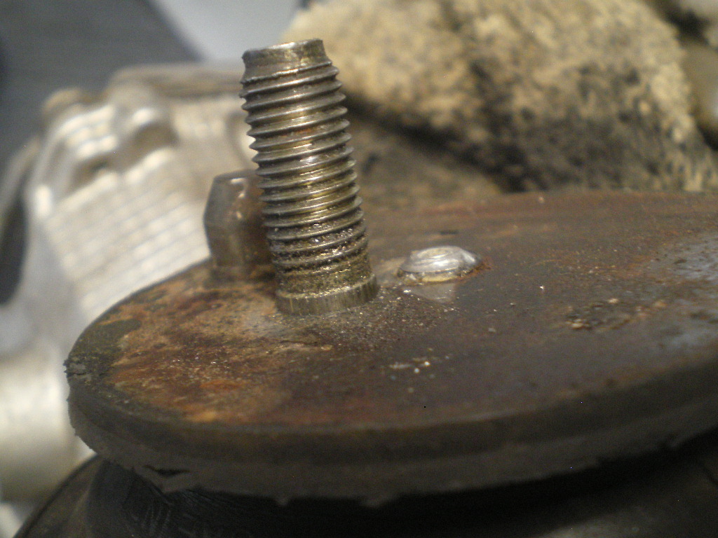 Attached image(s) 
|
|
|
|
| 76-914 |
Jul 8 2020, 03:37 PM
Post
#29
|
|
Repeat Offender & Resident Subaru Antagonist Group: Members Posts: 13,896 Joined: 23-January 09 From: Temecula, CA Member No.: 9,964 Region Association: Southern California |
The Poltergeist is back. That last pic isn't supposed to be there. I noticed it listed as an attachment in the edit file yet it didn't show on the version you see. So I added it where it belongs and lo and behold it shows up at the end of the post too. (IMG:style_emoticons/default/headbang.gif)
|
|
|
|
| 76-914 |
Jul 8 2020, 03:58 PM
Post
#30
|
|
Repeat Offender & Resident Subaru Antagonist Group: Members Posts: 13,896 Joined: 23-January 09 From: Temecula, CA Member No.: 9,964 Region Association: Southern California |
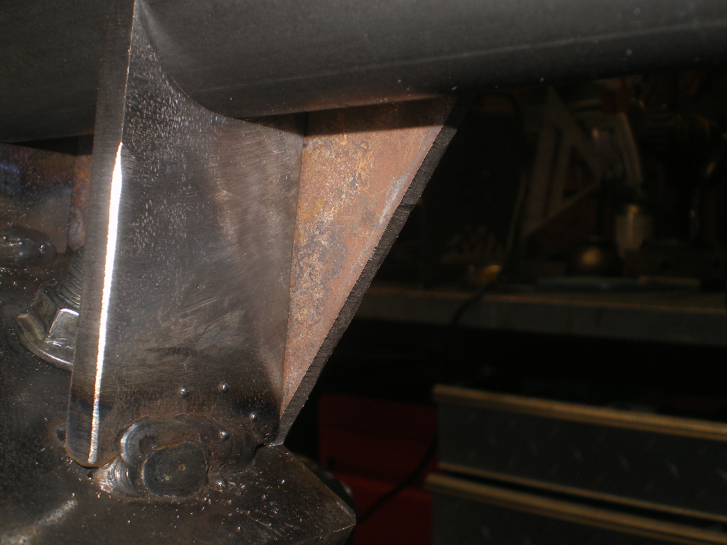
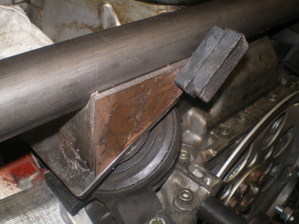
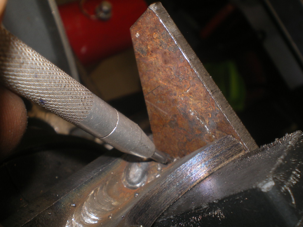
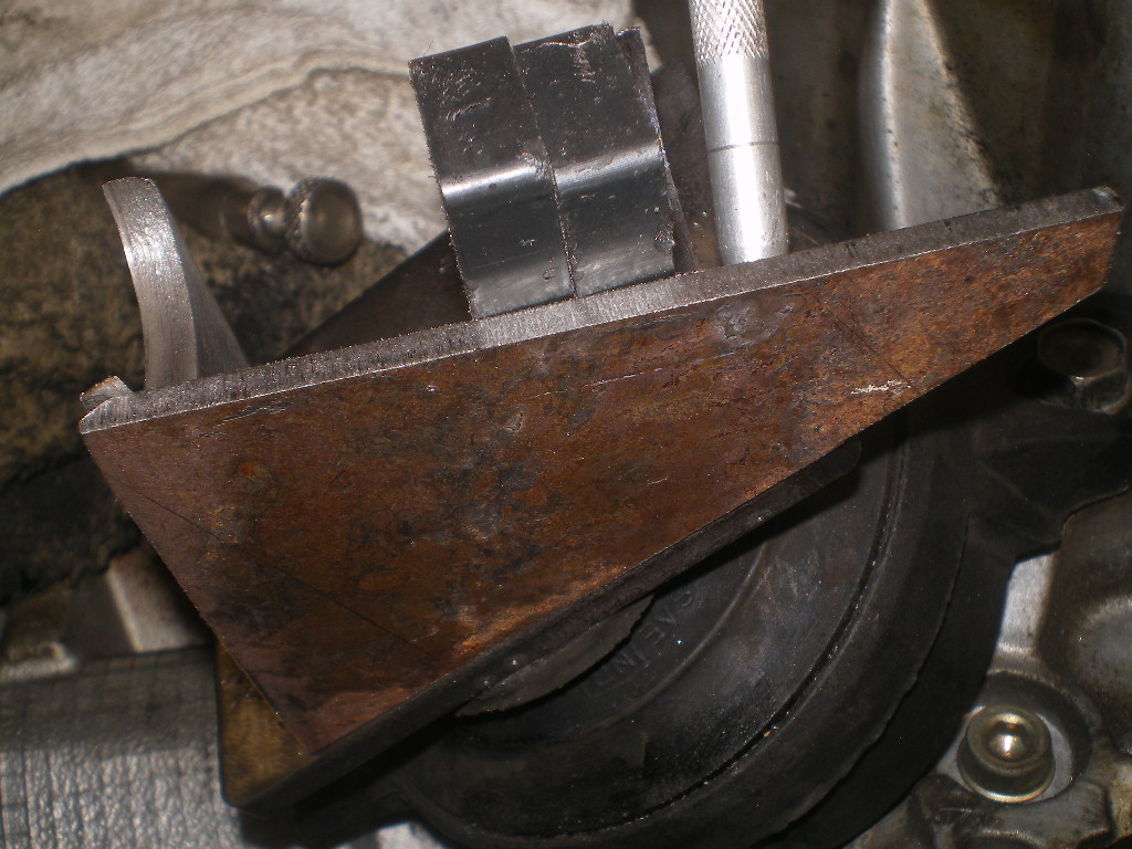
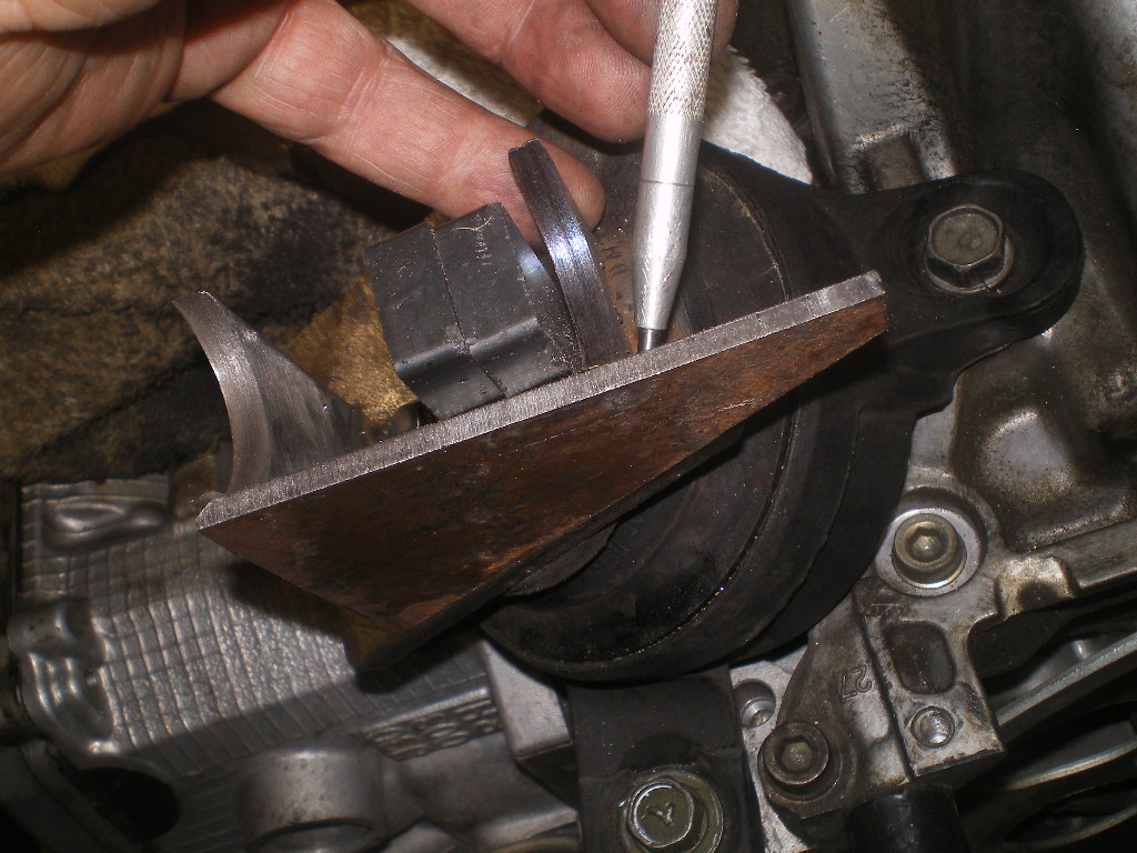
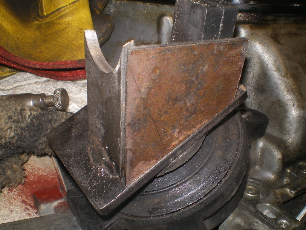
Now for the 3/16" reinforcing pieces. This rusty scrap looks like most of my steel before sanding the rust off but I leave it for now as it makes it easy to see the scribed marks. If it is new metal I use the dye. Just hold it in place and scribe the outline. After a couple of cuts and sanding it is complete. These won't be tacked in place for awhile as to give access to welding the bar to the tabs later.
                |
|
|
|
| 76-914 |
Jul 8 2020, 04:06 PM
Post
#31
|
|
Repeat Offender & Resident Subaru Antagonist Group: Members Posts: 13,896 Joined: 23-January 09 From: Temecula, CA Member No.: 9,964 Region Association: Southern California |
    And this is why I wear an apron when welding. After having some slag land in my belly button a few years back I quit tempting fate. (IMG:style_emoticons/default/new_shocked.gif) 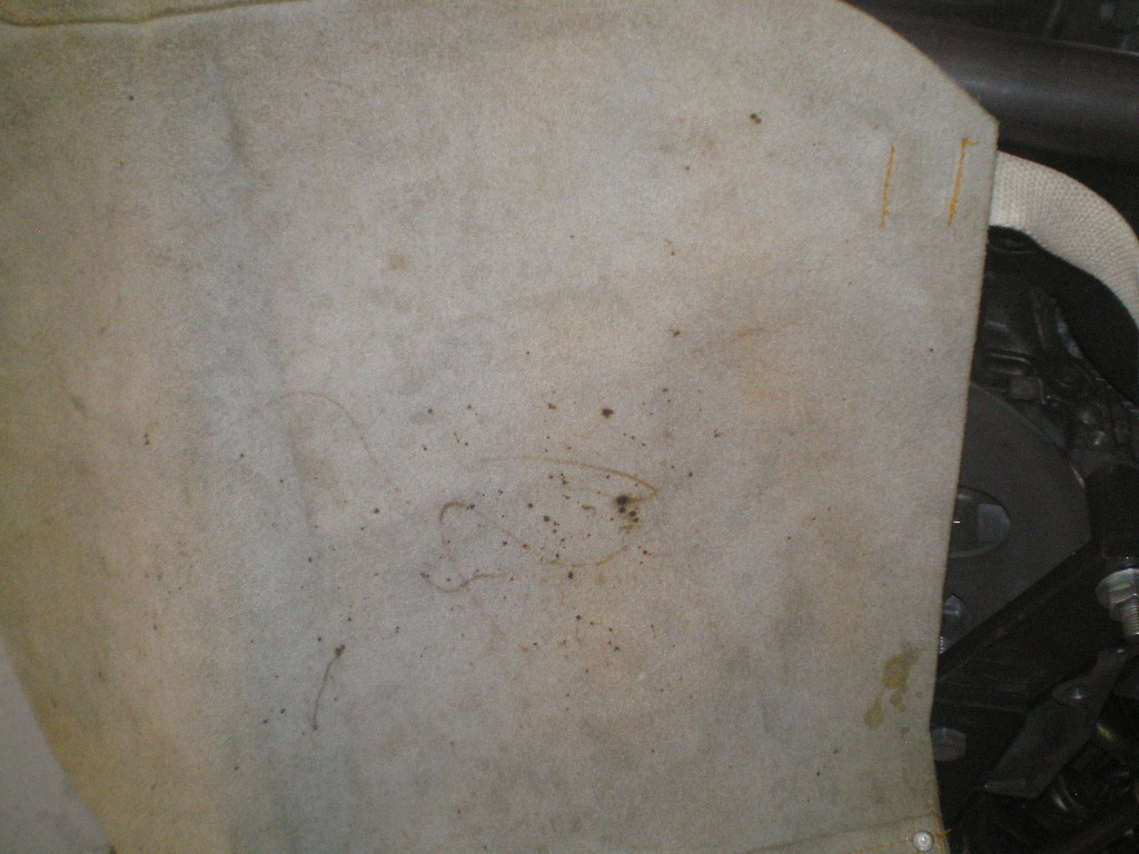 to be continued.................... |
|
|
|
| euro911 |
Jul 8 2020, 04:32 PM
Post
#32
|
|
Retired & living the dream. God help me if I wake up! Group: Members Posts: 8,937 Joined: 2-December 06 From: So.Cal. & No.AZ (USA) Member No.: 7,300 Region Association: Southern California |
Looking good, Kent. (subscribed)
|
|
|
|
| Andyrew |
Jul 9 2020, 08:45 AM
Post
#33
|
|
Spooling.... Please wait Group: Members Posts: 13,380 Joined: 20-January 03 From: Riverbank, Ca Member No.: 172 Region Association: Northern California |
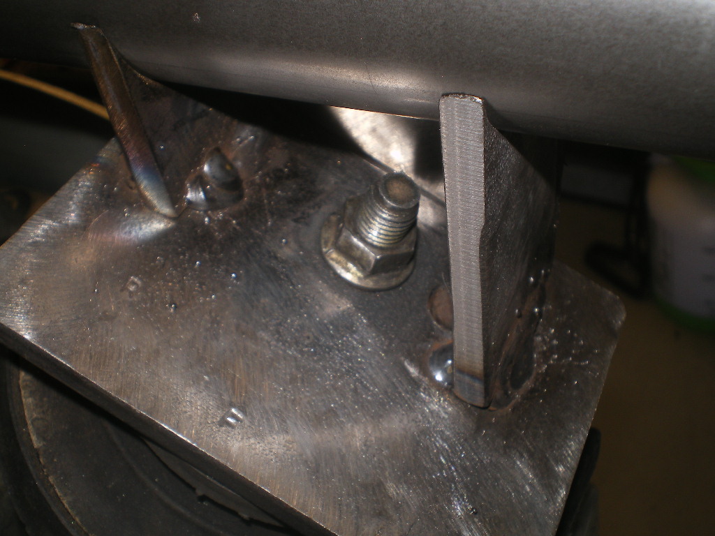
That looks STOUT! Might be going a bit overboard on the braces there Kent (IMG:style_emoticons/default/smile.gif)
Also remember disassembly when building. You have that bolt at an angle so you'll have to be able to pull it out at an angle when removing. Just FYI that could be difficult to coordinate. |
|
|
|
| 76-914 |
Jul 9 2020, 08:04 PM
Post
#34
|
|
Repeat Offender & Resident Subaru Antagonist Group: Members Posts: 13,896 Joined: 23-January 09 From: Temecula, CA Member No.: 9,964 Region Association: Southern California |
QUOTE(euro911 @ Jul 8 2020, 03:32 PM) Looking good, Kent. (subscribed) QUOTE(Andyrew @ Jul 9 2020, 07:45 AM) That looks STOUT! Might be going a bit overboard on the braces there Kent (IMG:style_emoticons/default/smile.gif) Also remember disassembly when building. You have that bolt at an angle so you'll have to be able to pull it out at an angle when removing. Just FYI that could be difficult to coordinate. @Andyrew Well I had the 1/4" on hand and I'm trying to limit my trips out. That CV19 thing. The first one I made from 3/16" and I've punished that set up w/o any problems. I did elongate the holes in the first one if you look at that build thread. I'm on the fence as to whether I should repeat that step or just loosen the rubber mount from the engine instead. I'll decide before I weld the bar in place so I can chunk them in the mill to elongate. http://www.914world.com/bbs2/uploads/post-...-1374796230.jpg |
|
|
|
| rhodyguy |
Jul 11 2020, 07:03 PM
Post
#35
|
|
Chimp Sanctuary NW. Check it out. Group: Members Posts: 22,252 Joined: 2-March 03 From: Orion's Bell. The BELL! Member No.: 378 Region Association: Galt's Gulch |
That's a very handsome table you have for your band saw.
|
|
|
|
| euro911 |
Jul 11 2020, 10:02 PM
Post
#36
|
|
Retired & living the dream. God help me if I wake up! Group: Members Posts: 8,937 Joined: 2-December 06 From: So.Cal. & No.AZ (USA) Member No.: 7,300 Region Association: Southern California |
QUOTE(76-914 @ Jul 9 2020, 07:04 PM) QUOTE(euro911 @ Jul 8 2020, 03:32 PM) Looking good, Kent. (subscribed) @euro911 Thank you sir. Have you started playing with that welder yet?? I did, however, purchase a HF welding cart and some supplies, but misplaced my helmet somewhere along the line (IMG:style_emoticons/default/headbang.gif) |
|
|
|
| 76-914 |
Jul 12 2020, 12:47 PM
Post
#37
|
|
Repeat Offender & Resident Subaru Antagonist Group: Members Posts: 13,896 Joined: 23-January 09 From: Temecula, CA Member No.: 9,964 Region Association: Southern California |
QUOTE(rhodyguy @ Jul 11 2020, 06:03 PM) That's a very handsome table you have for your band saw. QUOTE(euro911 @ Jul 11 2020, 09:02 PM) QUOTE(76-914 @ Jul 9 2020, 07:04 PM) QUOTE(euro911 @ Jul 8 2020, 03:32 PM) Looking good, Kent. (subscribed) @euro911 Thank you sir. Have you started playing with that welder yet?? I did, however, purchase a HF welding cart and some supplies, but misplaced my helmet somewhere along the line (IMG:style_emoticons/default/headbang.gif) Well don't let it intimidate you. Welding is a lot like fiberglassing. You can always grind it off and do it again. (IMG:style_emoticons/default/beerchug.gif) |
|
|
|
| 76-914 |
Jul 22 2020, 05:27 PM
Post
#38
|
|
Repeat Offender & Resident Subaru Antagonist Group: Members Posts: 13,896 Joined: 23-January 09 From: Temecula, CA Member No.: 9,964 Region Association: Southern California |
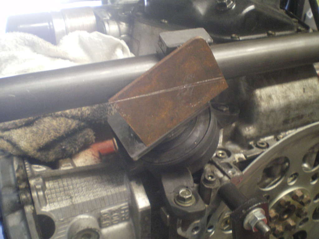
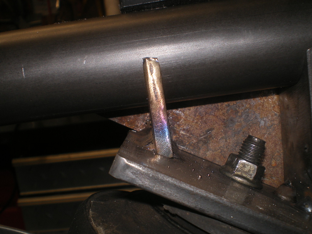
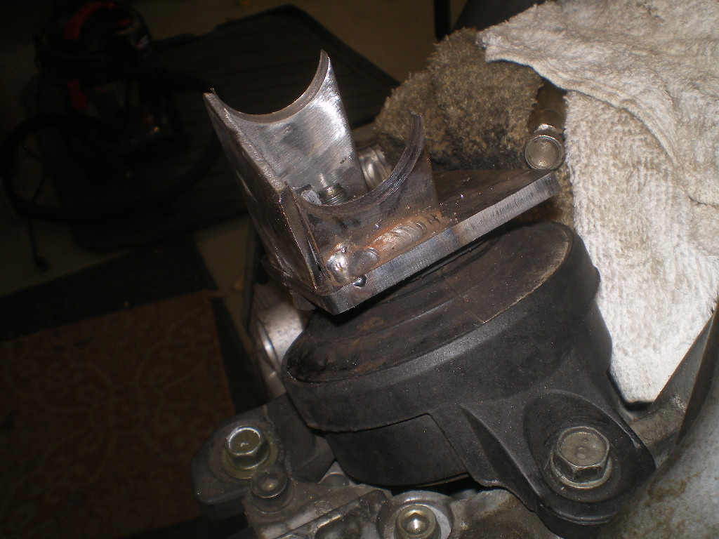
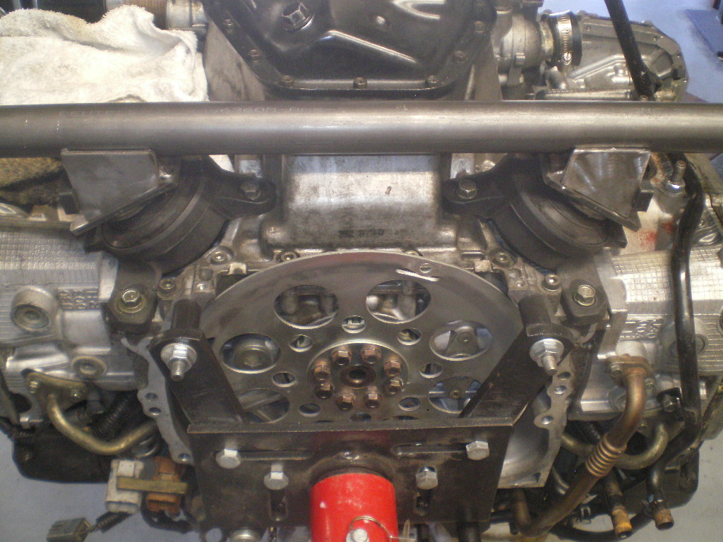
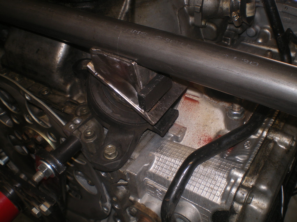
The steel spacers or bushing stock arrived last week so I was able to complete the engine cradle sans the transmission hanger part. Now that you know where the center of the front hangers are the next step is to drill those 1/4" out to 3/4". Since the arbor bit has a 1/4" pilot bit we will use that hole to align the 3/4" hole saw before drilling. To make sure I'm not "catty wamposed" I position the tube so that the 1/4" bit, still in the drill press, so that it bit passes freely thru both sides before clamping the tube in place. Next I remove the 1/4" bit and chuck the 3/4" arbor bit in place. Now it's just a matter of running the 3/4" bit thru. If you're "on the money" the steel spacer will need a bit of persuasion to pass thru the tube. If it doesn't, no big deal. It just makes it easier during the next few steps as it will not need to be hung or supported on this end.
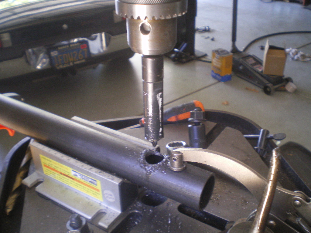 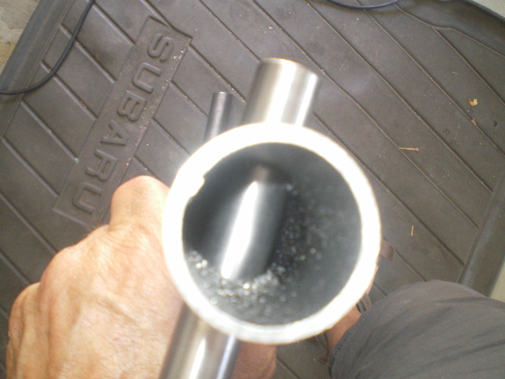 Here is the right side in place. The steel spacer is still 4" long at this point and will be cut down to 3" before welded in place. I know the picture shows to cut it 3 1/2" but that is incorrect. 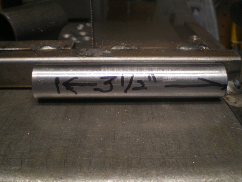 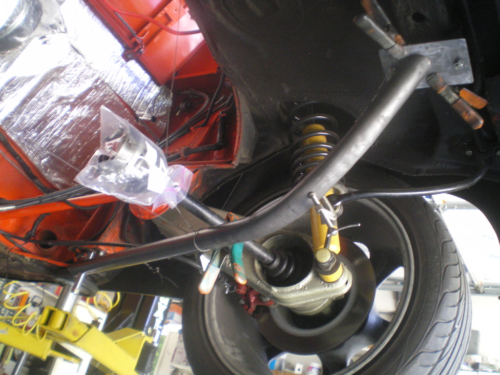 Now check the tube for level and adjust the tube up or down the steel spacer until it is level. Now check to see that the other end is in the correct spot on the 3"x4" plate. Once you're satisfied tack both ends and recheck for level and position. If it didn't slip or move go ahead and weld both ends as much as you can. You can finish any areas you miss once we remove the cradle from the car. Why do it this way? Shrinkage! I learned that lesson on my 1st cradle. By doing it this way we are using the car as a jig to prevent any shrinkage. It's a PITA welding overhead and in tight areas and your welds will look like (IMG:style_emoticons/default/stromberg.gif) but in the end you'll be glad you did. I think I'll make a jig for future cradles so I don't have to do this in the future. Oops doubled up on that last pic. 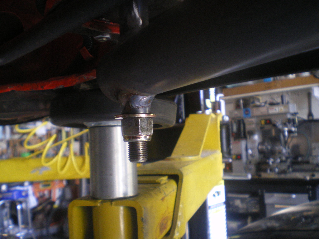 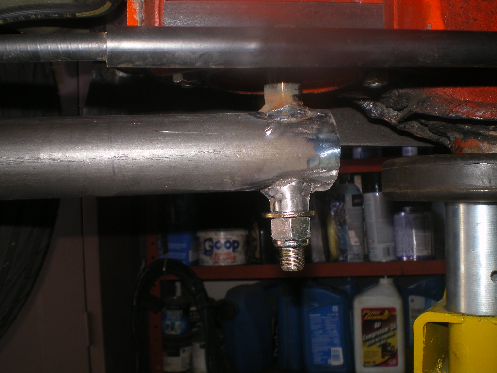 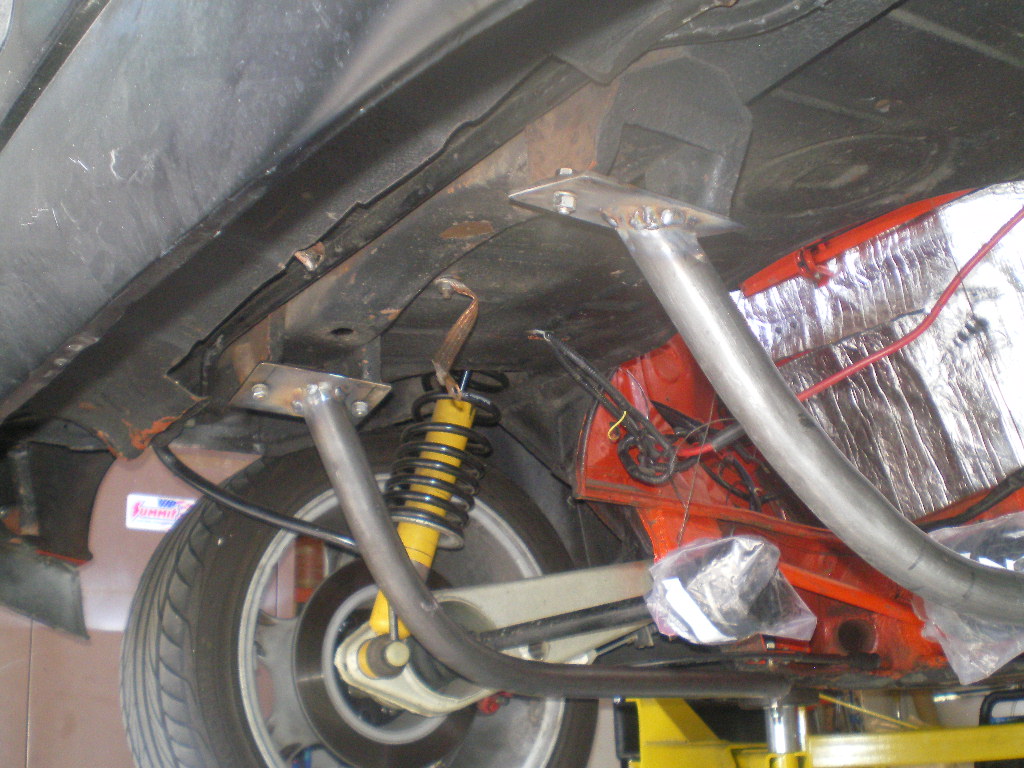 Attached image(s) 
|
|
|
|
| euro911 |
Jul 22 2020, 06:01 PM
Post
#39
|
|
Retired & living the dream. God help me if I wake up! Group: Members Posts: 8,937 Joined: 2-December 06 From: So.Cal. & No.AZ (USA) Member No.: 7,300 Region Association: Southern California |
You make it look like you know what you're doing there ... (IMG:style_emoticons/default/poke.gif)
|
|
|
|
| 76-914 |
Jul 22 2020, 06:32 PM
Post
#40
|
|
Repeat Offender & Resident Subaru Antagonist Group: Members Posts: 13,896 Joined: 23-January 09 From: Temecula, CA Member No.: 9,964 Region Association: Southern California |
Now it's time to take this cross member tube and cut it to length.
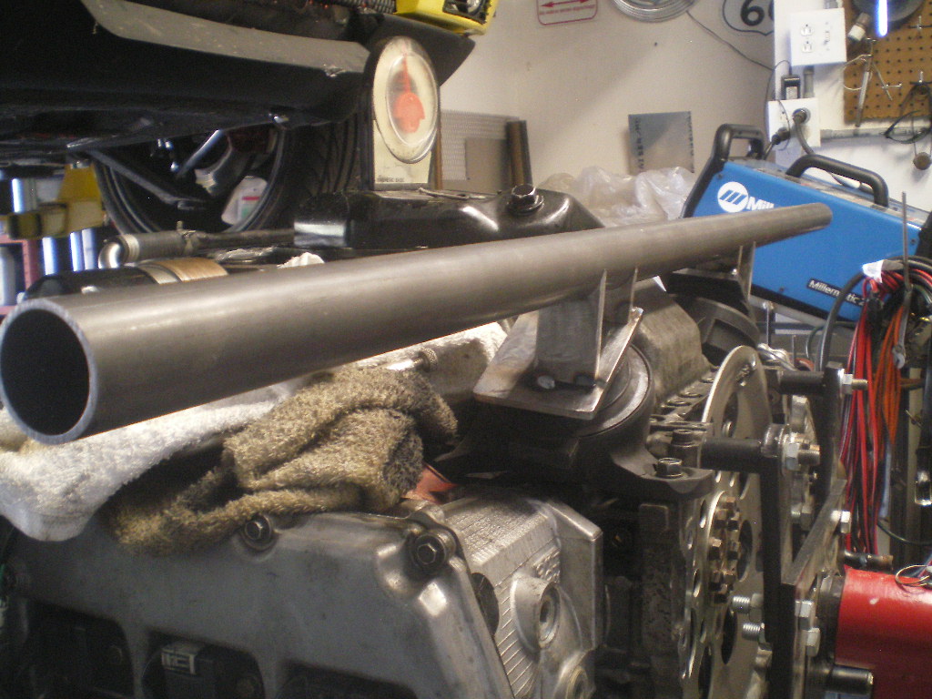 The ends will be drilled with an 1.5" arbor bit at a 110 degree (or 70 degree) angle depending upon which side you're measuring the angle. The end to end measurement taken on the edge of the holes on shortest side will be 30". I suggest you make it a little longer and trim to the final length once you're certain the 30" length will work for you. I'll explain further. Once both ends of the cross member are drilled one side is longer than the other since we are not drilling perpendicular to the pipe. I was distracted by "someone" when I started drilling and measured 30" from the edge of the hole on the long side and screwed that piece up. (IMG:style_emoticons/default/headbang.gif) So, it was a few days before I could get back up to Aircraft Spruce for a 3' piece to correct my boo-boo. Notice that small C clamp on one end. That was ground flat on one side so I could lay my level upon it. Once the first hole is drilled out the cross member is flipped end to end and re-inserted in the tube notcher and checked for level on the C clamp before tightening the tube down in the tube notcher. The C clamp will be on top during both operations. This keeps the drilled ends parallel to one another. 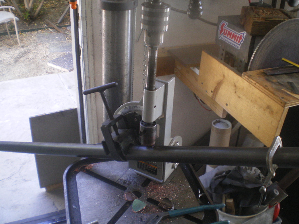 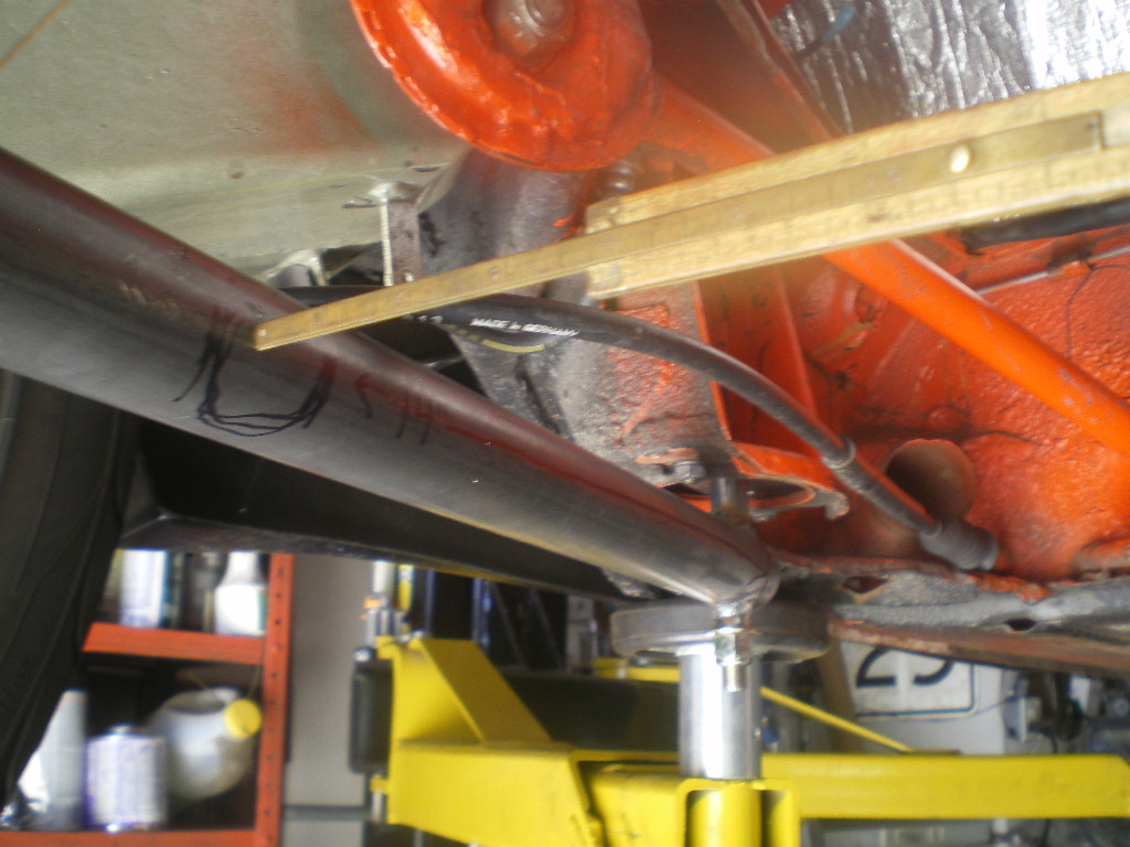 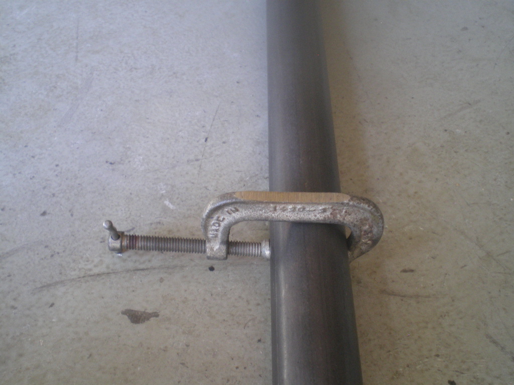 Before going any further I should explain where I got the 30" short edge to short edge dimension. I like to keep the axles centered with the output flanges on the transmission. To achieve this I need to have the center of the cross member 14" from the rear edge of the steel spacer. Just lay your rule on top of the tube and measure back 14". Then roughly draw an 1.5" circle on each side 14" from the center to the edge of the spacer. This will give you reference point for fitting the cross member.If you want your engine to sit closer to the firewall then you will need to adjust this dimension accordingly. Do not place the crossmember further towards the rear unless you want cut up your trunk floor. 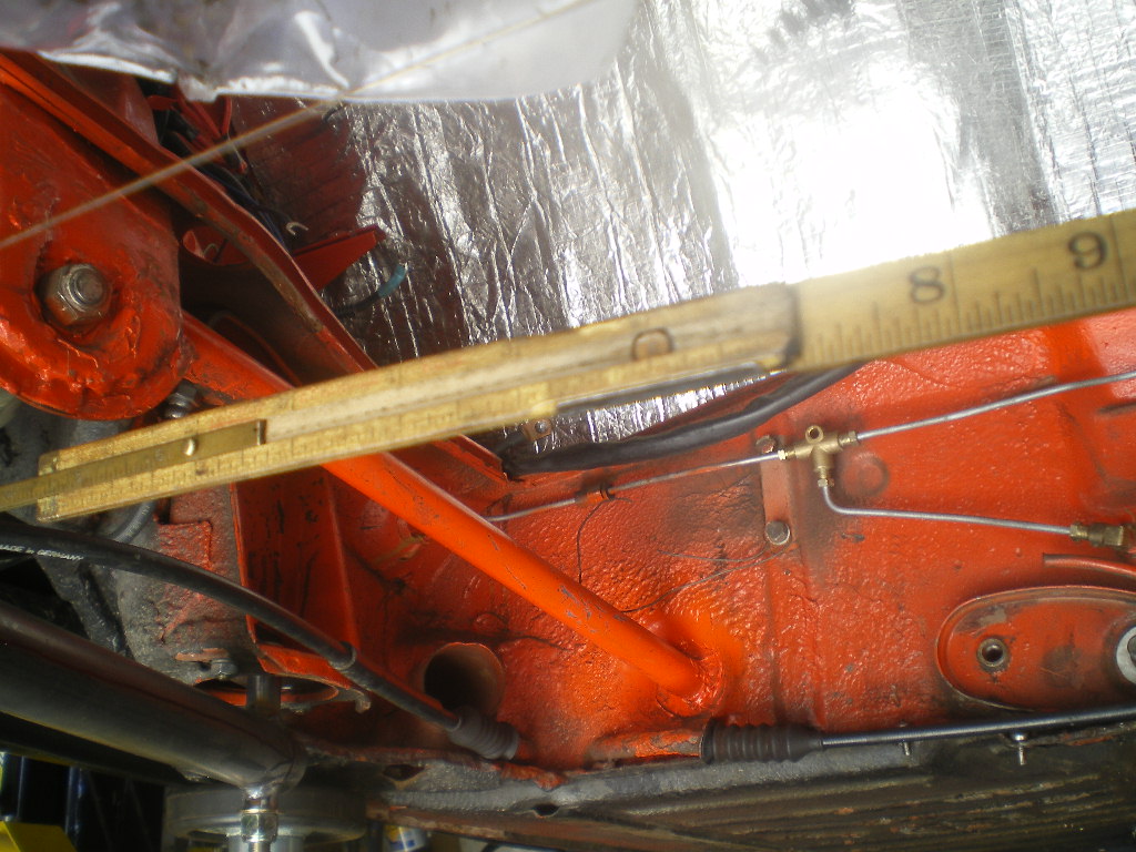 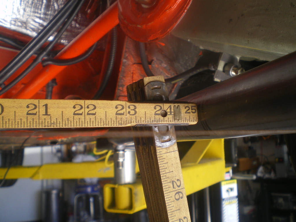 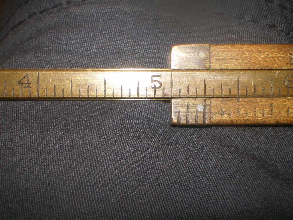 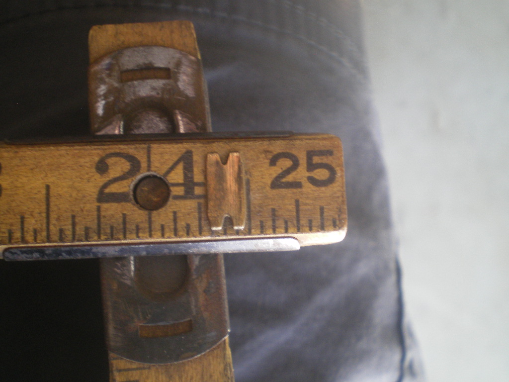 Once you're satisfied with the length you'll want to square it up before welding it in place. I used a string that was strung from the brake calipers. Once the string is taunt measure from the firewall back to either end. Those measurements should be equal; unless the car has some previous shoddy bodywork or Hans had a few beers at lunch. Now check the angle between the string and runners. That should be 110 or 70 degrees depending upon which side of the string you measure. Once secure tack weld both sides, double check your measurements then complete as much of the welds joints as you can. 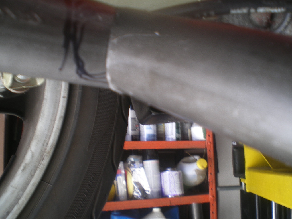 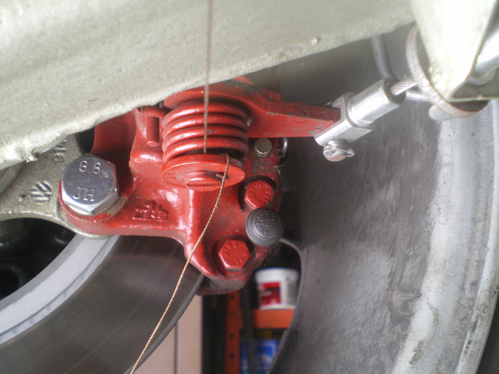 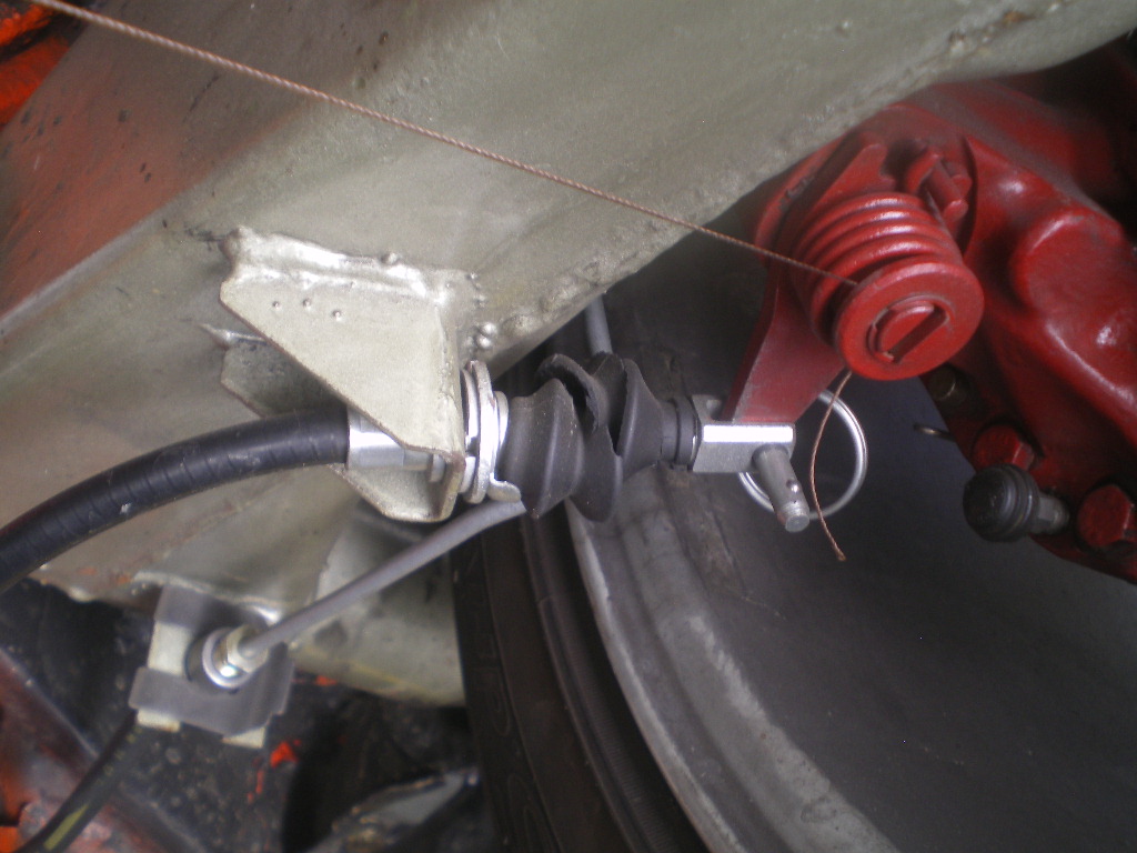 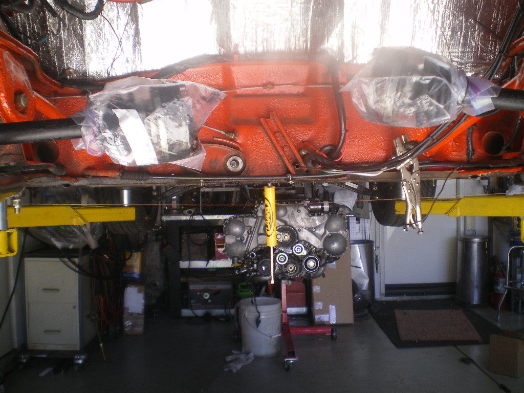 |
|
|
|
|
1 User(s) are reading this topic (1 Guests and 0 Anonymous Users)
0 Members:

|
Lo-Fi Version | Time is now: 16th June 2026 - 12:49 AM |
Invision Power Board
v9.1.4 © 2026 IPS, Inc.