|
|
|
Porsche, and the Porsche crest are registered trademarks of Dr. Ing. h.c. F. Porsche AG.
This site is not affiliated with Porsche in any way. Its only purpose is to provide an online forum for car enthusiasts. All other trademarks are property of their respective owners. |
|
|


| 76-914 |
 Jun 28 2020, 08:36 PM Jun 28 2020, 08:36 PM
Post
#61
|
|
Repeat Offender & Resident Subaru Antagonist  Group: Members Posts: 13,920 Joined: 23-January 09 From: Temecula, CA Member No.: 9,964 Region Association: Southern California |
The engine is sold. I'll soon have a very fresh 901 w/ an "H" gear for sale as well as some other goodies soon for those planning an SBC conversion. I couldn't do much with this sitting in my garage as it already is stuffed to the max. Therefor I felt it somewhat necessary to sell this before commencing with the re-conversion. I've been silently (yeh, I know; me silent) working in the background for a few months fabricating some items that will be needed. I'll do my best to document things a bit more accurately than the previous conversion. Once again I'll be using the Subaru 6 and Subaru transmission. I've had tremendous success with this platform so I might as well repeat myself. So sit back, bear with me and watch as I stumble along and occasionally embarrass myself. Mistakes are an integral part of my journey. (IMG:style_emoticons/default/beerchug.gif)
Attached image(s) 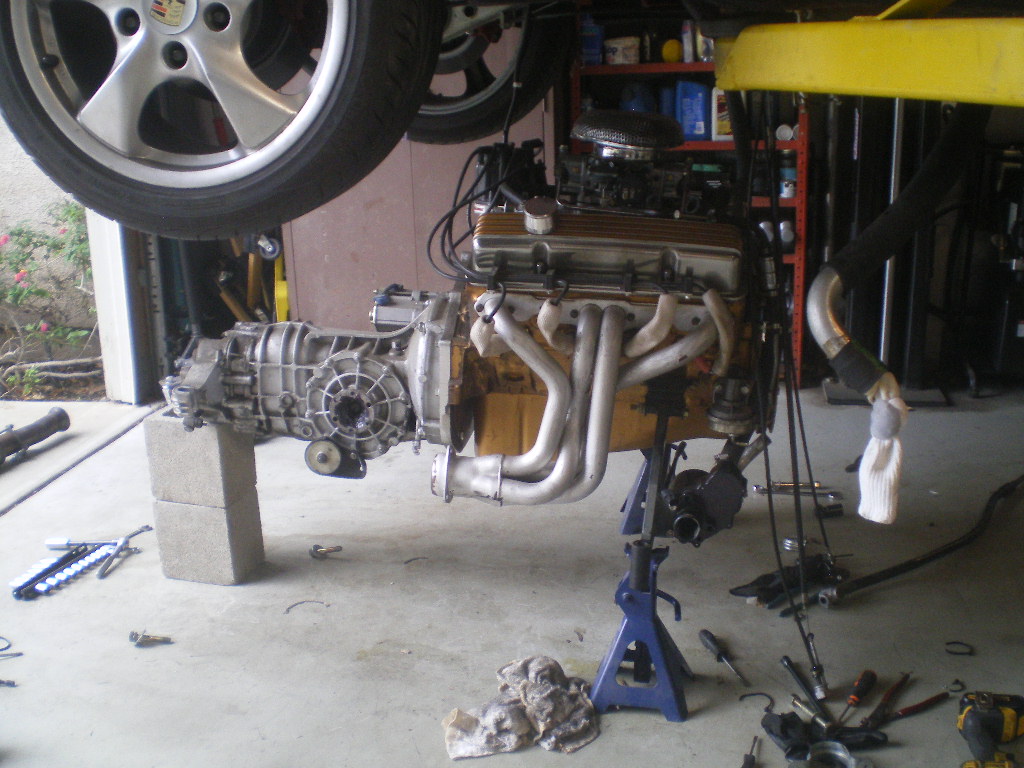
|
   |

 
|
Posts in this topic
76-914 Re-Conversion of a '70 914 Jun 28 2020, 08:36 PM tygaboy Yaaaa! Can't wait to see this one come (ba... Jun 28 2020, 09:31 PM
 76-914
Yaaaa! Can't wait to see this one come (b... Jun 30 2020, 04:52 PM EdwardBlume Love those Boxster rims. 70 was a good year. I kno... Jun 28 2020, 09:35 PM 76-914
Love those Boxster rims. 70 was a good year. I kn... Jun 30 2020, 04:53 PM 76-914 I've seen several requests for cradles in the ... Jun 30 2020, 05:44 PM flmont What are u thinking price wise on that 901 , Than... Jun 30 2020, 07:02 PM 76-914
What are u thinking price wise on that 901 , Tha... Jun 30 2020, 07:25 PM flmont Sold..! TY Jun 30 2020, 07:36 PM 76-914
Sold..! TY
PM sent Jun 30 2020, 08:05 PM flmont its still the same I did buy 914forme's crad... Jun 30 2020, 07:40 PM flmont I do need to read ChrisH,..posting on the heater c... Jun 30 2020, 07:44 PM 76-914 OK, back on track. If you plan to use 4130 chromol... Jul 3 2020, 06:11 PM tygaboy METAL!!!! :headbanger:
So cool ... Jul 3 2020, 06:53 PM 76-914 Go ahead and remove your old hardware from the fro... Jul 3 2020, 07:24 PM 808 WRX
Once it's is secure be sure the section past ... Jul 6 2020, 01:39 PM 76-914
Once it's is secure be sure the section past... Jul 6 2020, 09:51 PM 76-914 Now return the piece in place and hold the newly c... Jul 3 2020, 08:08 PM Andyrew :trophy: :popcorn: :welder:
Awesome!!... Jul 6 2020, 01:45 PM tygaboy
:trophy: :popcorn: :welder:
Awesome!... Jul 6 2020, 02:24 PM 914forme Love the low tech cradle build.
The roll of tap... Jul 6 2020, 02:32 PM JRust Looks great Kent! Love to see the step by step... Jul 6 2020, 08:40 PM 2mAn Love it. I could hear the garage cursing because I... Jul 6 2020, 09:02 PM 76-914
:trophy: :popcorn: :welder:
Awesome!... Jul 6 2020, 10:04 PM andys This is what I did for my cradle in case it helps.... Jul 7 2020, 11:24 AM 76-914
This is what I did for my cradle in case it helps... Jul 7 2020, 12:59 PM 76-914 Round 4; I was able to steal away for 2 hours this... Jul 7 2020, 09:38 PM 76-914 OK, things are fixing to get wordy so bare with me... Jul 8 2020, 03:29 PM 76-914 The Poltergeist is back. That last pic isn't s... Jul 8 2020, 03:37 PM 76-914 Now for the 3/16" reinforcing pieces. This ru... Jul 8 2020, 03:58 PM 76-914
And this is why I wear an apron when weld... Jul 8 2020, 04:06 PM euro911 Looking good, Kent. (subscribed) Jul 8 2020, 04:32 PM Andyrew That looks STOUT! Might be going a bit overboa... Jul 9 2020, 08:45 AM 76-914
Looking good, Kent. (subscribed)
@[url=http://ww... Jul 9 2020, 08:04 PM euro911 [quote name='euro911' post='2832137' date='Jul 8 2... Jul 11 2020, 10:02 PM rhodyguy That's a very handsome table you have for your... Jul 11 2020, 07:03 PM 76-914
That's a very handsome table you have for you... Jul 12 2020, 12:47 PM 76-914 The steel spacers or bushing stock arrived last we... Jul 22 2020, 05:27 PM euro911 You make it look like you know what you're doi... Jul 22 2020, 06:01 PM 76-914 Now it's time to take this cross member tube a... Jul 22 2020, 06:32 PM 76-914 Now remove the cradle from the car and place it up... Jul 22 2020, 07:03 PM flmont Man...That is so perfect !! Jul 23 2020, 01:45 PM 76-914
Man...That is so perfect !!
You jinxe... Aug 2 2020, 12:16 PM 76-914 And then there was this Heatwave........There went... Aug 24 2020, 09:20 PM 76-914 Oops. I didn't show any pics of the final crad... Aug 24 2020, 09:28 PM euro911 Since you drilled holes for the Schroeder valves, ... Aug 24 2020, 10:12 PM 914forme :agree: or other coating of your choice.
Fluid Fi... Aug 25 2020, 06:39 AM ValcoOscar Kent-
:wavebye:
I'm here for you if you de... Aug 25 2020, 09:48 AM 76-914
Kent-
:wavebye:
I'm here for you if you d... Aug 25 2020, 05:03 PM 76-914
Since you drilled holes for the Schroeder valves,... Aug 25 2020, 05:05 PM 76-914 I did get it in primer this morning. Hopefully I c... Aug 25 2020, 05:10 PM 76-914 Dressed her up with a new coat this morning. I... Aug 26 2020, 03:00 PM 808 WRX :cheer: Looking good! :beer2: Aug 26 2020, 03:22 PM 76-914 Thx, They're like women."They all look go... Aug 27 2020, 03:14 PM 76-914 So, before the afternoon heat crept in I was able ... Aug 27 2020, 03:33 PM rmarx Great thread! Thank you for posting all the de... Sep 11 2020, 05:41 PM 76-914 Sorry I'm late getting back to you @rmarx . J... Sep 16 2020, 05:37 PM Steve Impressive skills Kent!! As Ferdinand sai... Sep 16 2020, 07:05 PM rnellums Great work Kent. When I rebuilt my pedal assembly ... Sep 16 2020, 07:44 PM mgp4591
Great work Kent. When I rebuilt my pedal assembly... Sep 17 2020, 10:48 AM euro911 You master fabricator, you :headbanger: Sep 17 2020, 12:04 AM ValcoOscar Kent-
You are officially a WORLDLY MacGyver! ... Sep 17 2020, 11:24 AM 76-914
Impressive skills Kent!! As Ferdinand sa... Sep 17 2020, 07:19 PM 76-914 Picking up where I left off. Here is a pic of the ... Sep 22 2020, 01:48 PM 76-914 And a couple of "finished product" shots... Sep 22 2020, 01:50 PM 76-914 Half shafts are out. After cut to length & the... Sep 24 2020, 04:34 PM 76-914 The first thing I did was remove the 4 bolts from ... Sep 30 2020, 01:26 PM 914Subaru Kent,
This new project is looking good. I was ins... Oct 1 2020, 07:28 PM 76-914
Kent,
This new project is looking good. I was in... Oct 2 2020, 10:20 AM Gint Excellent work Kent! Subscribed
@76-914
[q... Oct 5 2020, 10:05 PM Montreal914 Nice shifter location. :)
How far back from the ... Oct 1 2020, 09:24 PM 76-914
Nice shifter location. :)
How far back from the... Oct 2 2020, 10:26 AM 76-914
Nice shifter location. :)
How far back from the... Oct 29 2020, 04:27 PM 76-914 The fuel hose arrived this weekend so I was able t... Oct 5 2020, 06:30 PM Montreal914 Thank you for the added shifter information. Looki... Oct 5 2020, 08:34 PM euro911 Hey, Mike ( @[url=http://www.914world.com/bbs2/ind... Oct 5 2020, 11:31 PM Gint
Hey, Mike ( @[url=http://www.914world.com/bbs2/in... Oct 6 2020, 04:40 PM 76-914 Future Oct 24 2020, 05:05 PM 76-914 I thought I should post this for any of you guys t... Oct 26 2020, 09:23 PM Montreal914 Thank you :beer2:
That is very similar to the 91... Oct 29 2020, 08:47 PM 76-914 It's been a few weeks and only a few items rem... Nov 9 2020, 06:04 PM 76-914 Then clamp together and weld. I use this term weld... Nov 9 2020, 06:09 PM 76-914 All of the plumbing is completed and tied in with ... Nov 9 2020, 06:25 PM FL 000 No idea how I have missed this thread until now. N... Nov 9 2020, 06:56 PM 914GTSTI Thanks for all the great Ideas ! Your the MAN ... Dec 1 2020, 10:11 PM Chris H. Looks great Kent! What size radiator hoses di... Dec 1 2020, 10:33 PM 76-914
Looks great Kent! What size radiator hoses d... Dec 2 2020, 04:50 AM Chris H.
Looks great Kent! What size radiator hoses ... Dec 2 2020, 01:16 PM 76-914 I have some catching up to do here. I received my ... Dec 11 2020, 11:56 AM rhodyguy Party ON! Dec 11 2020, 12:08 PM Mueller Nice job, might have to borrow a few of your desig... Dec 11 2020, 02:12 PM 76-914 Thx Mike. Well, I went to way much trouble install... Dec 25 2020, 05:09 PM 76-914 If it ain't one thing it's two. I've b... Jan 12 2021, 10:40 AM BillJ Very cool build and thanks for sharing it! Ar... Jan 12 2021, 11:17 AM 76-914
Very cool build and thanks for sharing it! A... Jan 12 2021, 07:01 PM rhodyguy How many turbos on the replacement 6? 2? Jan 12 2021, 07:06 PM Chris914n6 I'd check the harness too to make sure that... Jan 12 2021, 08:46 PM 76-914
I'd check the harness too to make sure that... Jan 13 2021, 10:21 AM 76-914 Well it's been 5 weeks and I wish I were furth... Feb 24 2021, 09:10 PM 76-914 So the newest engine runs great, pulls strong and ... Feb 24 2021, 09:34 PM
76-914
Yaaaa! Can't wait to see this one come (b... Jun 30 2020, 04:52 PM EdwardBlume Love those Boxster rims. 70 was a good year. I kno... Jun 28 2020, 09:35 PM 76-914
Love those Boxster rims. 70 was a good year. I kn... Jun 30 2020, 04:53 PM 76-914 I've seen several requests for cradles in the ... Jun 30 2020, 05:44 PM flmont What are u thinking price wise on that 901 , Than... Jun 30 2020, 07:02 PM 76-914
What are u thinking price wise on that 901 , Tha... Jun 30 2020, 07:25 PM flmont Sold..! TY Jun 30 2020, 07:36 PM 76-914
Sold..! TY
PM sent Jun 30 2020, 08:05 PM flmont its still the same I did buy 914forme's crad... Jun 30 2020, 07:40 PM flmont I do need to read ChrisH,..posting on the heater c... Jun 30 2020, 07:44 PM 76-914 OK, back on track. If you plan to use 4130 chromol... Jul 3 2020, 06:11 PM tygaboy METAL!!!! :headbanger:
So cool ... Jul 3 2020, 06:53 PM 76-914 Go ahead and remove your old hardware from the fro... Jul 3 2020, 07:24 PM 808 WRX
Once it's is secure be sure the section past ... Jul 6 2020, 01:39 PM 76-914
Once it's is secure be sure the section past... Jul 6 2020, 09:51 PM 76-914 Now return the piece in place and hold the newly c... Jul 3 2020, 08:08 PM Andyrew :trophy: :popcorn: :welder:
Awesome!!... Jul 6 2020, 01:45 PM tygaboy
:trophy: :popcorn: :welder:
Awesome!... Jul 6 2020, 02:24 PM 914forme Love the low tech cradle build.
The roll of tap... Jul 6 2020, 02:32 PM JRust Looks great Kent! Love to see the step by step... Jul 6 2020, 08:40 PM 2mAn Love it. I could hear the garage cursing because I... Jul 6 2020, 09:02 PM 76-914
:trophy: :popcorn: :welder:
Awesome!... Jul 6 2020, 10:04 PM andys This is what I did for my cradle in case it helps.... Jul 7 2020, 11:24 AM 76-914
This is what I did for my cradle in case it helps... Jul 7 2020, 12:59 PM 76-914 Round 4; I was able to steal away for 2 hours this... Jul 7 2020, 09:38 PM 76-914 OK, things are fixing to get wordy so bare with me... Jul 8 2020, 03:29 PM 76-914 The Poltergeist is back. That last pic isn't s... Jul 8 2020, 03:37 PM 76-914 Now for the 3/16" reinforcing pieces. This ru... Jul 8 2020, 03:58 PM 76-914
And this is why I wear an apron when weld... Jul 8 2020, 04:06 PM euro911 Looking good, Kent. (subscribed) Jul 8 2020, 04:32 PM Andyrew That looks STOUT! Might be going a bit overboa... Jul 9 2020, 08:45 AM 76-914
Looking good, Kent. (subscribed)
@[url=http://ww... Jul 9 2020, 08:04 PM euro911 [quote name='euro911' post='2832137' date='Jul 8 2... Jul 11 2020, 10:02 PM rhodyguy That's a very handsome table you have for your... Jul 11 2020, 07:03 PM 76-914
That's a very handsome table you have for you... Jul 12 2020, 12:47 PM 76-914 The steel spacers or bushing stock arrived last we... Jul 22 2020, 05:27 PM euro911 You make it look like you know what you're doi... Jul 22 2020, 06:01 PM 76-914 Now it's time to take this cross member tube a... Jul 22 2020, 06:32 PM 76-914 Now remove the cradle from the car and place it up... Jul 22 2020, 07:03 PM flmont Man...That is so perfect !! Jul 23 2020, 01:45 PM 76-914
Man...That is so perfect !!
You jinxe... Aug 2 2020, 12:16 PM 76-914 And then there was this Heatwave........There went... Aug 24 2020, 09:20 PM 76-914 Oops. I didn't show any pics of the final crad... Aug 24 2020, 09:28 PM euro911 Since you drilled holes for the Schroeder valves, ... Aug 24 2020, 10:12 PM 914forme :agree: or other coating of your choice.
Fluid Fi... Aug 25 2020, 06:39 AM ValcoOscar Kent-
:wavebye:
I'm here for you if you de... Aug 25 2020, 09:48 AM 76-914
Kent-
:wavebye:
I'm here for you if you d... Aug 25 2020, 05:03 PM 76-914
Since you drilled holes for the Schroeder valves,... Aug 25 2020, 05:05 PM 76-914 I did get it in primer this morning. Hopefully I c... Aug 25 2020, 05:10 PM 76-914 Dressed her up with a new coat this morning. I... Aug 26 2020, 03:00 PM 808 WRX :cheer: Looking good! :beer2: Aug 26 2020, 03:22 PM 76-914 Thx, They're like women."They all look go... Aug 27 2020, 03:14 PM 76-914 So, before the afternoon heat crept in I was able ... Aug 27 2020, 03:33 PM rmarx Great thread! Thank you for posting all the de... Sep 11 2020, 05:41 PM 76-914 Sorry I'm late getting back to you @rmarx . J... Sep 16 2020, 05:37 PM Steve Impressive skills Kent!! As Ferdinand sai... Sep 16 2020, 07:05 PM rnellums Great work Kent. When I rebuilt my pedal assembly ... Sep 16 2020, 07:44 PM mgp4591
Great work Kent. When I rebuilt my pedal assembly... Sep 17 2020, 10:48 AM euro911 You master fabricator, you :headbanger: Sep 17 2020, 12:04 AM ValcoOscar Kent-
You are officially a WORLDLY MacGyver! ... Sep 17 2020, 11:24 AM 76-914
Impressive skills Kent!! As Ferdinand sa... Sep 17 2020, 07:19 PM 76-914 Picking up where I left off. Here is a pic of the ... Sep 22 2020, 01:48 PM 76-914 And a couple of "finished product" shots... Sep 22 2020, 01:50 PM 76-914 Half shafts are out. After cut to length & the... Sep 24 2020, 04:34 PM 76-914 The first thing I did was remove the 4 bolts from ... Sep 30 2020, 01:26 PM 914Subaru Kent,
This new project is looking good. I was ins... Oct 1 2020, 07:28 PM 76-914
Kent,
This new project is looking good. I was in... Oct 2 2020, 10:20 AM Gint Excellent work Kent! Subscribed
@76-914
[q... Oct 5 2020, 10:05 PM Montreal914 Nice shifter location. :)
How far back from the ... Oct 1 2020, 09:24 PM 76-914
Nice shifter location. :)
How far back from the... Oct 2 2020, 10:26 AM 76-914
Nice shifter location. :)
How far back from the... Oct 29 2020, 04:27 PM 76-914 The fuel hose arrived this weekend so I was able t... Oct 5 2020, 06:30 PM Montreal914 Thank you for the added shifter information. Looki... Oct 5 2020, 08:34 PM euro911 Hey, Mike ( @[url=http://www.914world.com/bbs2/ind... Oct 5 2020, 11:31 PM Gint
Hey, Mike ( @[url=http://www.914world.com/bbs2/in... Oct 6 2020, 04:40 PM 76-914 Future Oct 24 2020, 05:05 PM 76-914 I thought I should post this for any of you guys t... Oct 26 2020, 09:23 PM Montreal914 Thank you :beer2:
That is very similar to the 91... Oct 29 2020, 08:47 PM 76-914 It's been a few weeks and only a few items rem... Nov 9 2020, 06:04 PM 76-914 Then clamp together and weld. I use this term weld... Nov 9 2020, 06:09 PM 76-914 All of the plumbing is completed and tied in with ... Nov 9 2020, 06:25 PM FL 000 No idea how I have missed this thread until now. N... Nov 9 2020, 06:56 PM 914GTSTI Thanks for all the great Ideas ! Your the MAN ... Dec 1 2020, 10:11 PM Chris H. Looks great Kent! What size radiator hoses di... Dec 1 2020, 10:33 PM 76-914
Looks great Kent! What size radiator hoses d... Dec 2 2020, 04:50 AM Chris H.
Looks great Kent! What size radiator hoses ... Dec 2 2020, 01:16 PM 76-914 I have some catching up to do here. I received my ... Dec 11 2020, 11:56 AM rhodyguy Party ON! Dec 11 2020, 12:08 PM Mueller Nice job, might have to borrow a few of your desig... Dec 11 2020, 02:12 PM 76-914 Thx Mike. Well, I went to way much trouble install... Dec 25 2020, 05:09 PM 76-914 If it ain't one thing it's two. I've b... Jan 12 2021, 10:40 AM BillJ Very cool build and thanks for sharing it! Ar... Jan 12 2021, 11:17 AM 76-914
Very cool build and thanks for sharing it! A... Jan 12 2021, 07:01 PM rhodyguy How many turbos on the replacement 6? 2? Jan 12 2021, 07:06 PM Chris914n6 I'd check the harness too to make sure that... Jan 12 2021, 08:46 PM 76-914
I'd check the harness too to make sure that... Jan 13 2021, 10:21 AM 76-914 Well it's been 5 weeks and I wish I were furth... Feb 24 2021, 09:10 PM 76-914 So the newest engine runs great, pulls strong and ... Feb 24 2021, 09:34 PM  |
1 User(s) are reading this topic (1 Guests and 0 Anonymous Users)
0 Members:

|
Lo-Fi Version | Time is now: 25th July 2026 - 12:25 AM |
Invision Power Board
v9.1.4 © 2026 IPS, Inc.