|
|
|
Porsche, and the Porsche crest are registered trademarks of Dr. Ing. h.c. F. Porsche AG.
This site is not affiliated with Porsche in any way. Its only purpose is to provide an online forum for car enthusiasts. All other trademarks are property of their respective owners. |
|
|

  |

| friethmiller |
 Aug 27 2024, 06:48 AM Aug 27 2024, 06:48 AM
Post
#161
|
|
Senior Member  Group: Members Posts: 1,214 Joined: 10-February 19 From: Austin, TX Member No.: 22,863 Region Association: Southwest Region |
Just looking through your latest post / pictures. Excellent work. The heater pipe is pretty easy to do. Just don't try to weld the heat tube clips to the longitudinal - like I did on my first 914 (IMG:style_emoticons/default/headbang.gif). Didn't work. I overside the holes just a bit and go with a larger pop-rivet. Depending on the amount of rust work needed for the inner rocker and inner wheelhouse area, you'll be buttoning up the drivers side soon.
|
   |

 
|
| dtmehall |
Aug 28 2024, 06:28 PM
Post
#162
|
|
Member Group: Members Posts: 265 Joined: 21-December 23 From: Michigan Member No.: 27,808 Region Association: Upper MidWest |
Here are photos from the work in process on my car in the body shop, with the end result
Attached image(s) 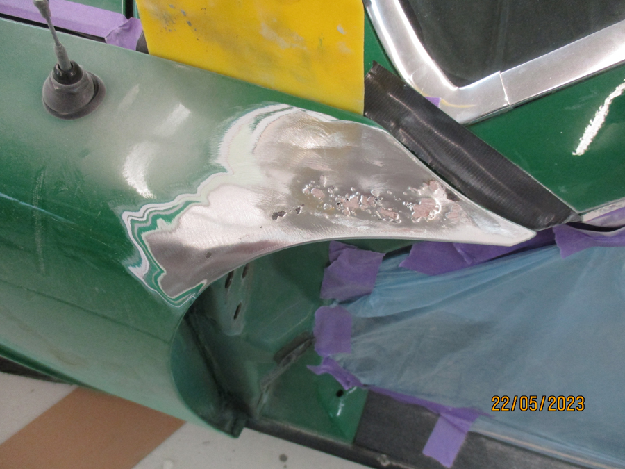 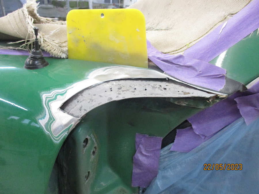 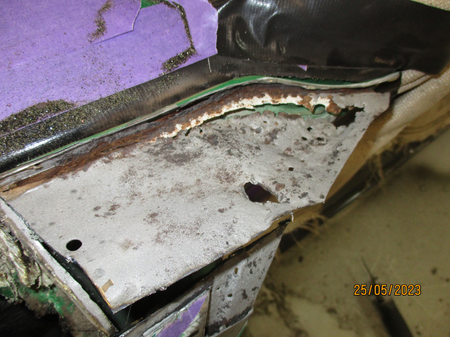 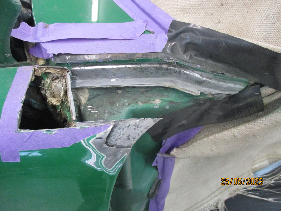 
|
|
|
|
| dtmehall |
Aug 28 2024, 07:23 PM
Post
#163
|
|
Member Group: Members Posts: 265 Joined: 21-December 23 From: Michigan Member No.: 27,808 Region Association: Upper MidWest |
btw, the body shop working on my car fabricated all the panels.
|
|
|
|
| Montreal914 |
Jul 7 2025, 12:11 PM
Post
#164
|
|
Advanced Member Group: Members Posts: 2,075 Joined: 8-August 10 From: Claremont, CA Member No.: 12,023 Region Association: Southern California |
WOW! (IMG:style_emoticons/default/sad.gif) I just noticed that my last post is almost a year old... Well a lot has happened since then. This restoration is now becoming a six conversion with all that it entails. (IMG:style_emoticons/default/driving.gif)
I did some progress on the chassis but mostly on getting some of the critical components for the conversion. So, I believe this is where we were 10+ months ago. (IMG:style_emoticons/default/rolleyes.gif)  Now, for the recent work. Time to remove the rest of the inner rocker panel so I can remove the insulated duct remains and see the overall condition of the front of the long. 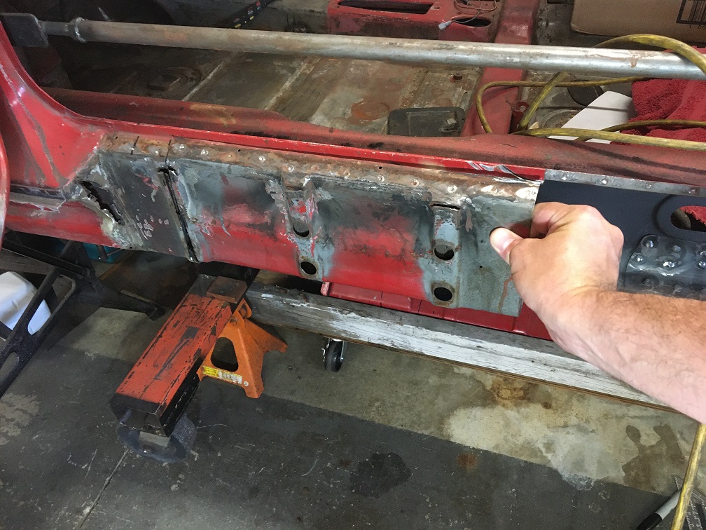 The 3/4" holes you are seeing in the inner rocker are the remains of me removing the Brad Mayer repair panels I had installed about 15 years ago, when I was driving the car... 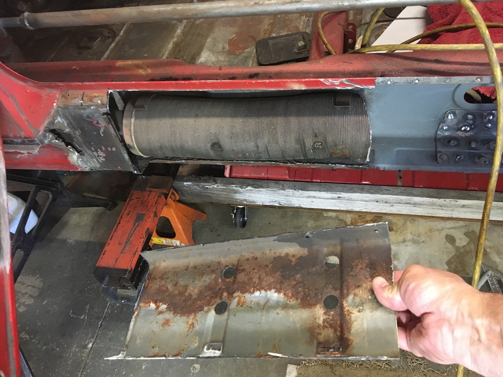 This is all healthy metal with a thin layer of rust powder. Great news! 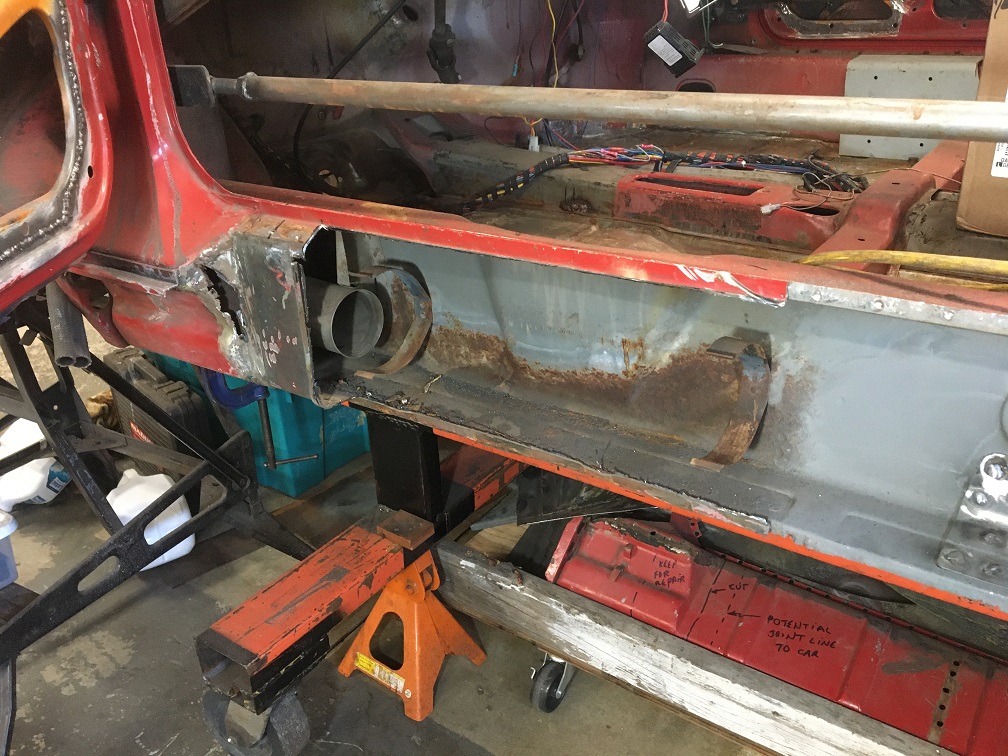 Once cleaned up, we can now see the back side of the typical crack on the front lower corner of the E-brake recess.  And here it is with back lighting for those who couldn't locate it. (IMG:style_emoticons/default/biggrin.gif) The light makes it a lot wider than it actually is. 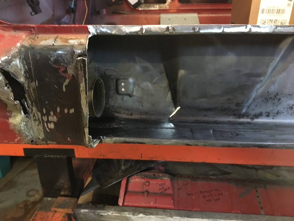 So, the fix could be as simple as rewelding it, and this will be part of it... 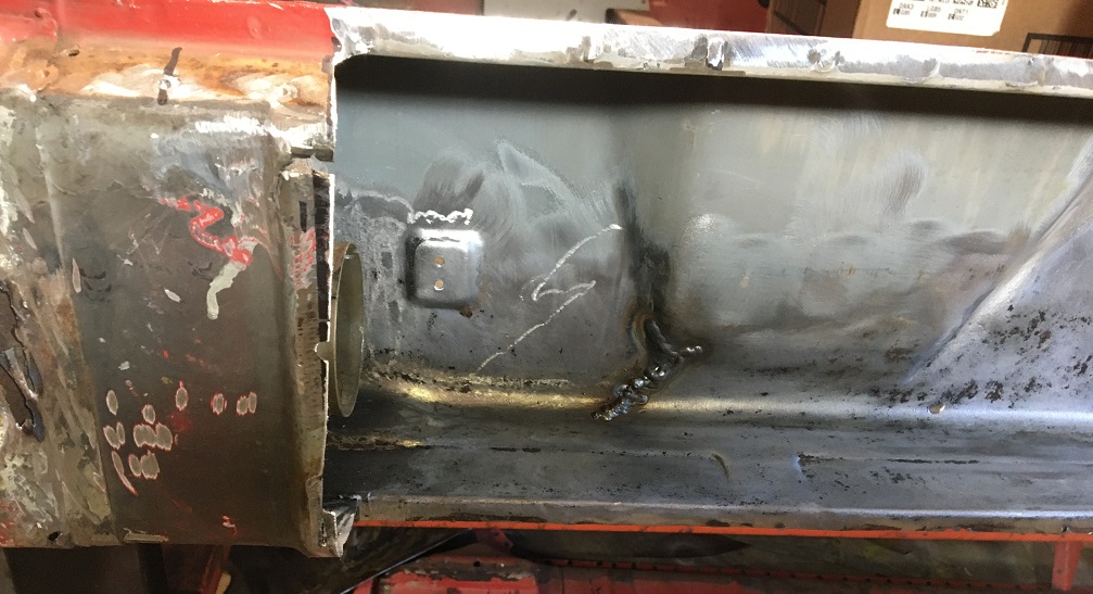 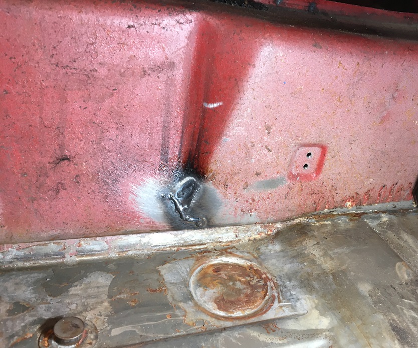 ...But rewelding will not solve the problem of it being a weak area from the begining. So, I decided to reinforce the area using a donor part. 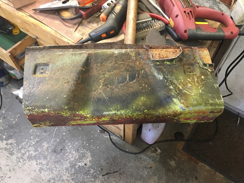 After removing all of the non-needed metal and clened up, it's looking promising! (IMG:style_emoticons/default/smile.gif) Since this double layer reinforcement will be inside, it need to be shorter by 2x the metal thickess, which will be achived by cutting it lengthwise with a thin abrasive disk on the 4" grinder. 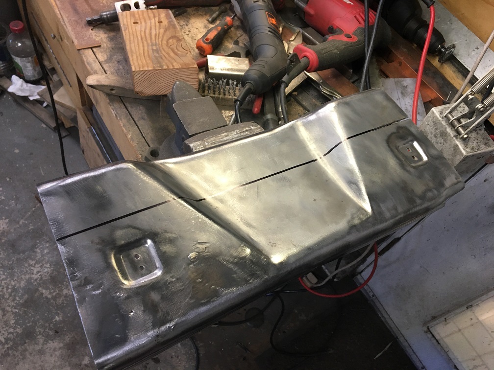 Now all prepped and ready to go in, bottom first. 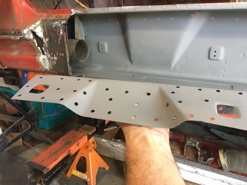 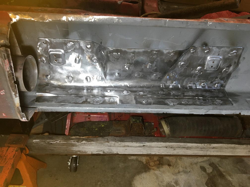 And top piece 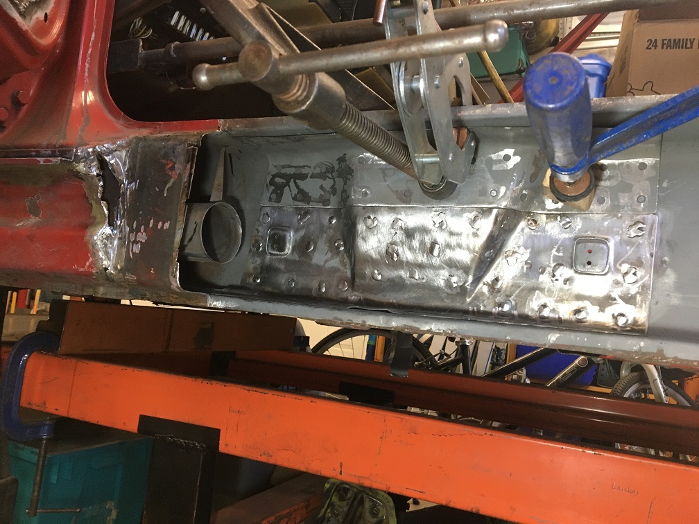 Final result (IMG:style_emoticons/default/beer3.gif) (IMG:style_emoticons/default/sunglasses.gif) I think this should help eliminating this problem. 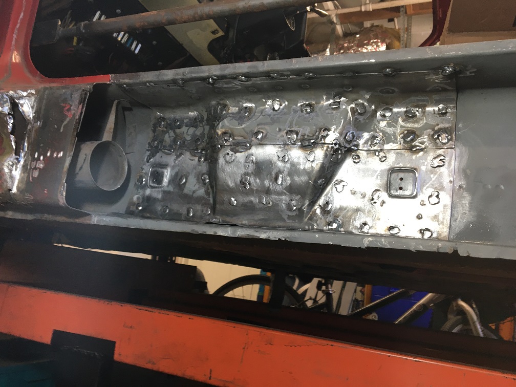 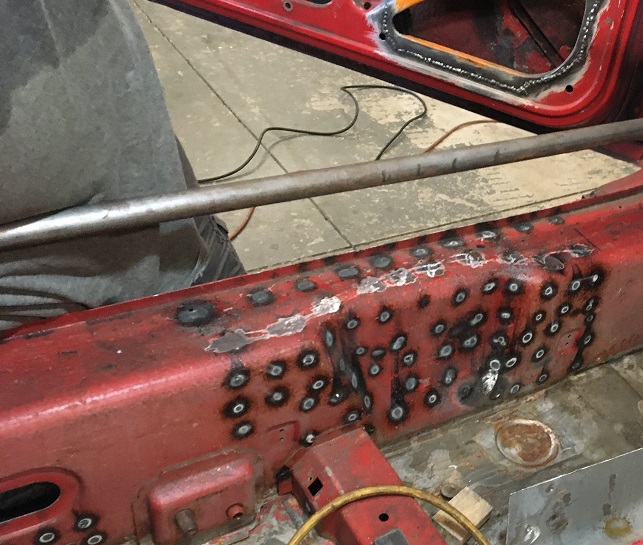 Another good step. More already done progess coming up! (IMG:style_emoticons/default/smash.gif) |
|
|
|
| friethmiller |
Jul 7 2025, 12:42 PM
Post
#165
|
|
Senior Member Group: Members Posts: 1,214 Joined: 10-February 19 From: Austin, TX Member No.: 22,863 Region Association: Southwest Region |
Excellent work! (IMG:style_emoticons/default/cheer.gif) You'll be driving this thing soon. I just hit the 3-year mark on restoring the LE. I guess certainly things are worth waiting for!
|
|
|
|
| Montreal914 |
Jul 7 2025, 12:57 PM
Post
#166
|
|
Advanced Member Group: Members Posts: 2,075 Joined: 8-August 10 From: Claremont, CA Member No.: 12,023 Region Association: Southern California |
QUOTE(friethmiller @ Jul 7 2025, 11:42 AM)  Excellent work! (IMG:style_emoticons/default/cheer.gif) You'll be driving this thing soon. I just hit the 3-year mark on restoring the LE. I guess certainly things are worth waiting for! 3 years already! (IMG:style_emoticons/default/blink.gif) WOW! ...Driving it soon, we'll see. I started with the easy side (driver's) but I still have to tackle the passenger's after. (IMG:style_emoticons/default/headbang.gif) The good thing is, I will know what to expect. |
|
|
|
| Montreal914 |
Jul 13 2025, 10:22 AM
Post
#167
|
|
Advanced Member Group: Members Posts: 2,075 Joined: 8-August 10 From: Claremont, CA Member No.: 12,023 Region Association: Southern California |
Following the previous inside the long reinforcement of the handbrake recess area, I started looking at the cabin side of the long. To stiffen the chassis, I have decided to install an inner kit from Maddogs (Engman's RIP design).
Although this 16ga. steel panel precut is pretty good, there are a few things I wanted different. This led to a very slippery slope as you will see in the following pictures. First, I did not like the fact that the lower sidewall is extending below the lower fillet/radius of the long. There is something about that fit that did not look right to me. The following two pictures explain what I am referring to. Initial fit shows how the panel is very close to the floor pan hiding a zone in the back where original seam sealer would be. 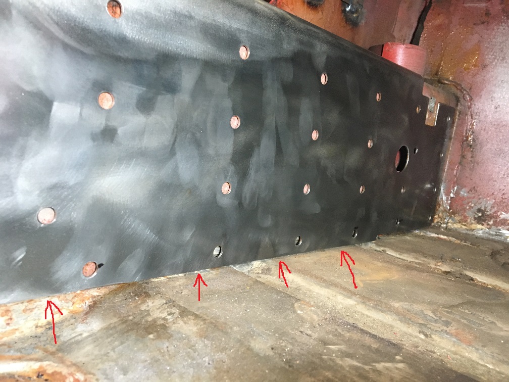 Here I trimmed about 1/2" of the lower edge so it can end on the long sidewall before the lower radius. 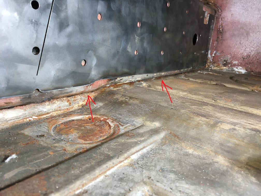 Next I went and trimmed around the contour and adjusted the clerance cuts for the seat belt anchor point, hand brake pivot, and square cross member so the stiffening panel was laying flat on the long surface without overlapping any of the hand brake pivot and cross member flanges. 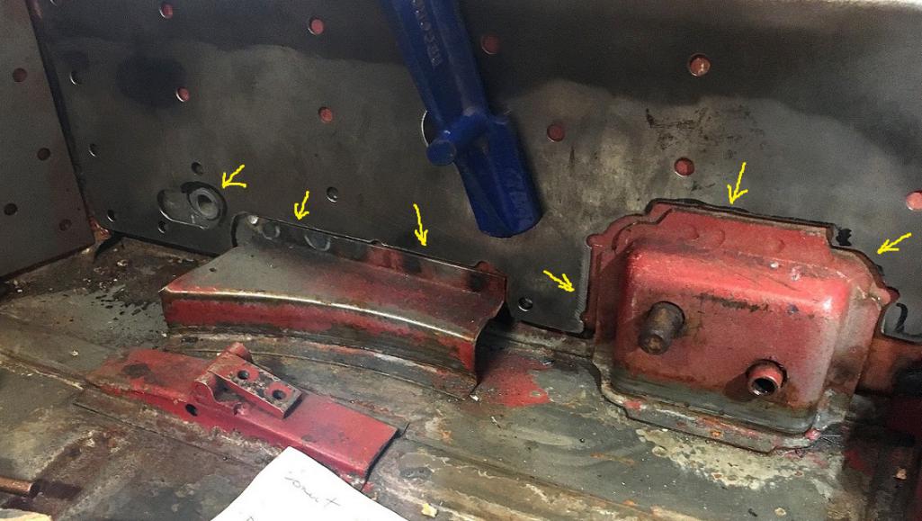 Move on to pre shaping the the hand brake recess. One of the way to do this is tacking the panel in place and forming the recess while plug welding the rest of it. I chose to fully preform the panel before doing any of the plug welding. Why? (IMG:style_emoticons/default/screwy.gif) Anyhow, this is how I did it. 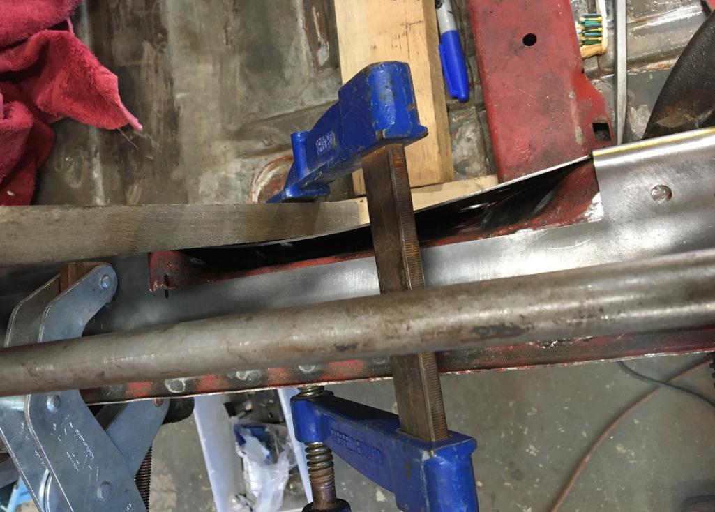 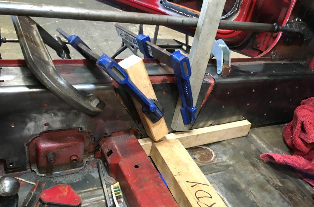 Now this is where the panel preparation takes a new tangent. With the recess panel nicely formed, I simply did not like the opening around it and went all out. (IMG:style_emoticons/default/rolleyes.gif) First, need to fill the gaps on either side, this one is easy. 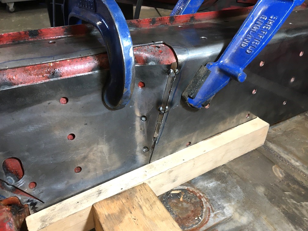 Then move on to the top opening which requires a little more work... (IMG:style_emoticons/default/smash.gif) 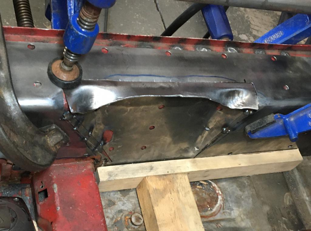 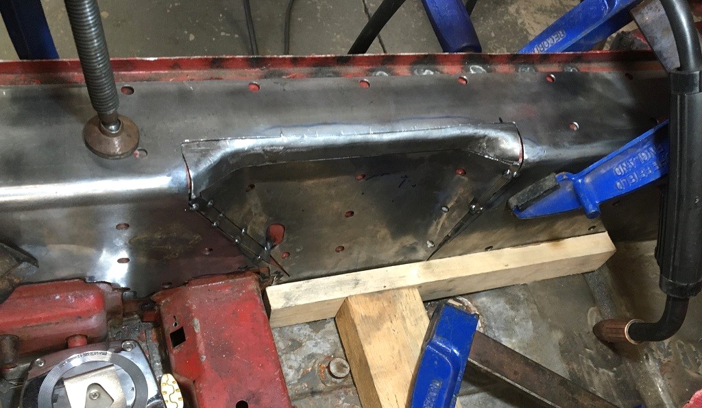 Looks promising! (IMG:style_emoticons/default/smile.gif) 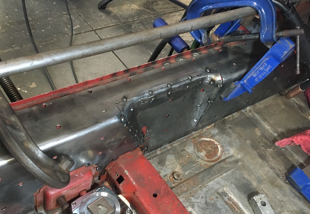 Then move the panel out and completed all of the welding. (IMG:style_emoticons/default/welder.gif) 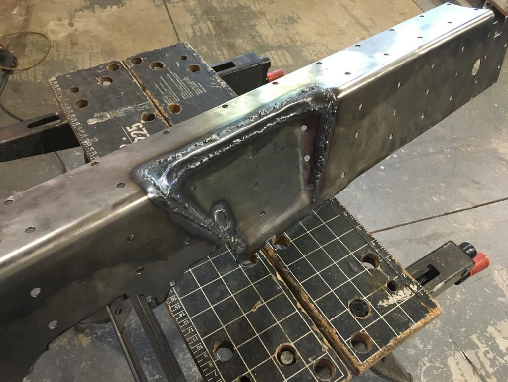 Final result, form fitted driver side inner stiffening panel. 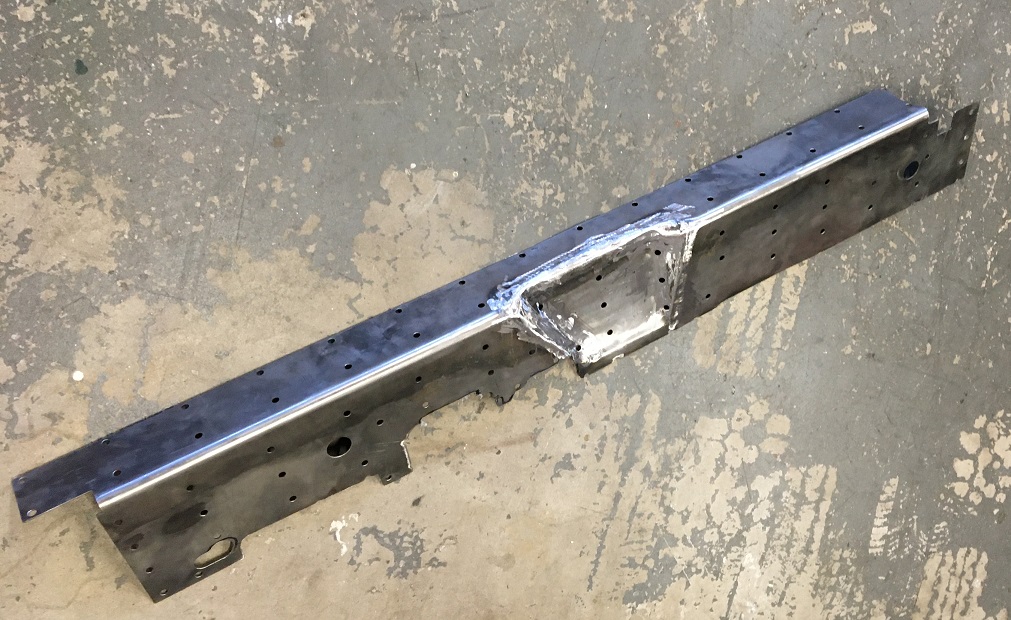 ...and because I am not a pro, this happened. (IMG:style_emoticons/default/rolleyes.gif) but it will be corrected accordingly. 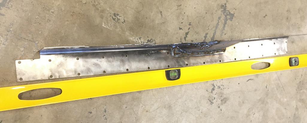 Part 2, installation, coming soon hopefully... stay tuned! |
|
|
|
| nivekdodge |
Jul 13 2025, 07:37 PM
Post
#168
|
|
Member Group: Members Posts: 332 Joined: 28-August 21 From: Pittsburgh Pa Member No.: 25,860 Region Association: MidAtlantic Region |
Looking good ERic I have tons of faith in you!
Kevin |
|
|
|
| slowrodent |
Jul 14 2025, 06:56 AM
Post
#169
|
|
Member Group: Members Posts: 225 Joined: 29-February 20 From: Tucson/Oro Valley Member No.: 23,981 Region Association: Southwest Region |
Wow... That;s beautiful work! (IMG:style_emoticons/default/cheer.gif) Kudos
|
|
|
|
| friethmiller |
Jul 14 2025, 07:58 AM
Post
#170
|
|
Senior Member Group: Members Posts: 1,214 Joined: 10-February 19 From: Austin, TX Member No.: 22,863 Region Association: Southwest Region |
Eric, Nice job! I went back an looked at my posts about this repair (pic below). I remember trimming these support pieces back about 1/4" or so on the bottom and then having to widened the openings for the the hand-brake and other fixtures. You need room to weld on the flat side of the long, IMO. Keep up the good work, sir (IMG:style_emoticons/default/first.gif)
 |
|
|
|
| Montreal914 |
Jul 14 2025, 10:54 AM
Post
#171
|
|
Advanced Member Group: Members Posts: 2,075 Joined: 8-August 10 From: Claremont, CA Member No.: 12,023 Region Association: Southern California |
@friethmiller Fred, looks like you fully welded the perimeter of the stiffener.
How did you manage this without shrinking the entire long? (IMG:style_emoticons/default/pray.gif) As for the clearance around the hand brakes and add-ons, I did get my inspiration on another reference rebuilt thread. (IMG:style_emoticons/default/biggrin.gif) (IMG:style_emoticons/default/poke.gif) |
|
|
|
| friethmiller |
Jul 14 2025, 11:58 AM
Post
#172
|
|
Senior Member Group: Members Posts: 1,214 Joined: 10-February 19 From: Austin, TX Member No.: 22,863 Region Association: Southwest Region |
QUOTE(Montreal914 @ Jul 14 2025, 11:54 AM) How did you manage this without shrinking the entire long? Easy! The long is well "long"... just ping pong around the parameter with 3 or 4 spot welds at a time. Trick is to never hammer a bunch of heat in one place. It takes a while to do this, of course. BTW, the front swaybar reinforcement is another kit that you'll need to "adjust". I'm not sure what 914 they templated the metal from but it ain't right (IMG:style_emoticons/default/blink.gif). Or, maybe every 914 I've ever worked on is a completely dogged-out POS. Might be the latter. (IMG:style_emoticons/default/confused24.gif) Your work around the hand brake is the tits! Way better than what I did, IMO. |
|
|
|
| Montreal914 |
Aug 9 2025, 02:38 PM
Post
#173
|
|
Advanced Member Group: Members Posts: 2,075 Joined: 8-August 10 From: Claremont, CA Member No.: 12,023 Region Association: Southern California |
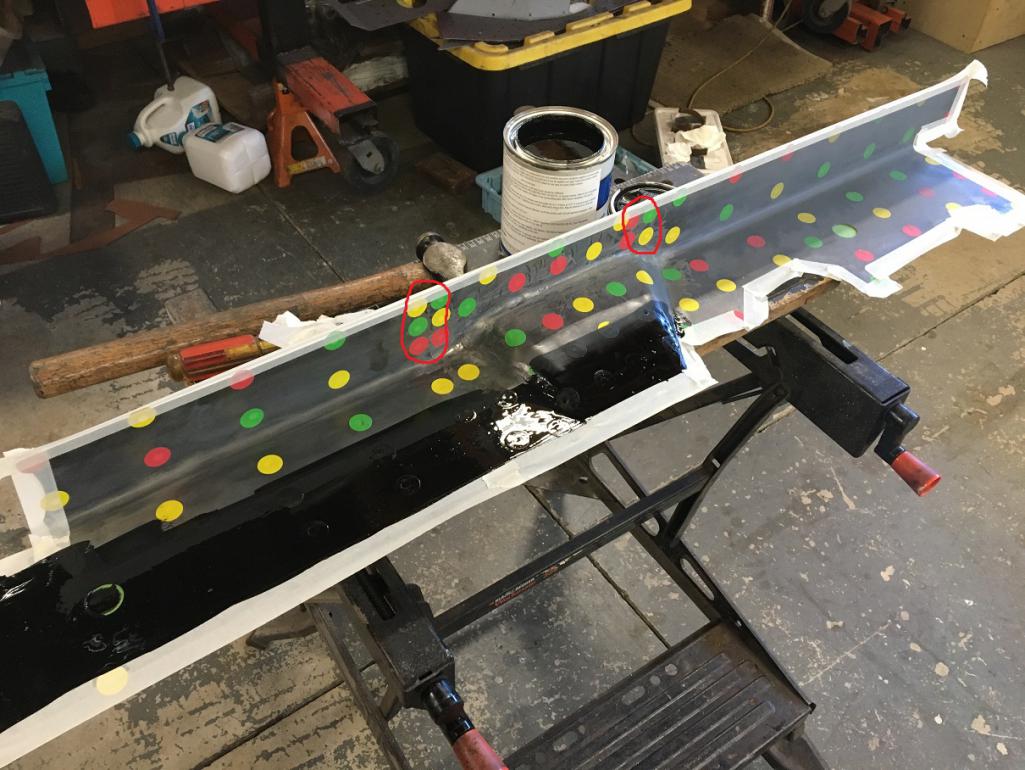
More progress to share... After trying to straighten the bent piece, I elected to make two cut and reweld on each side of the hand brake relief in the horizontal surface (cilcled in red). Below in the picture, I am coating the inside of the stiffening piece while masking around the holes where I will apply weld through primer.
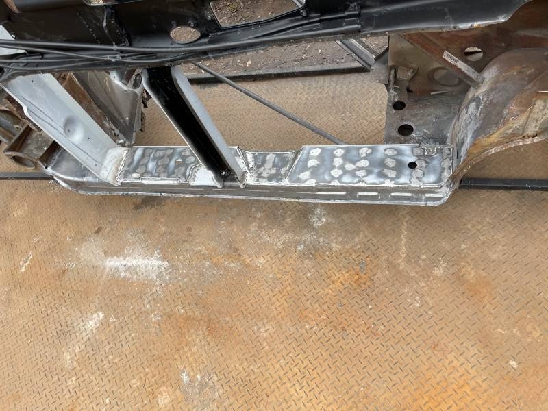
 Then I removed the paint on the cabin side of the long. You can see the metal discoloration from the plug weld of the reinforcement layer I installed inside the long at the hand brake relief area. 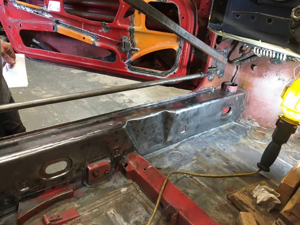 Then I apllied weld through primer. I should have given the same treatment I did on the stiffening panel, but oh well, this car will be kept indoors and pampered for the rest of my ownership...  Moving on to welding the stiffening piece. I took my sweet time and made sure the area was kept cool with this big copper bar acting as a heat sink next to where I was welding. You can also see the cut and reweld that was done to strighten the piece (last post problem). 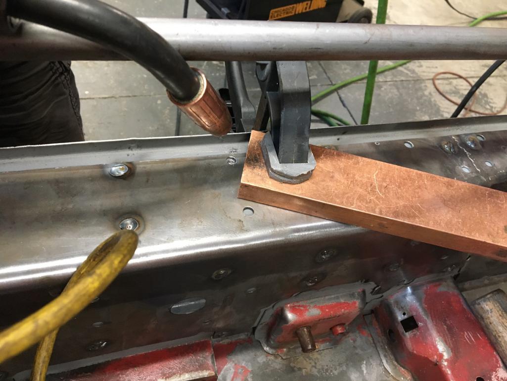 All done welding which pretty much took a couple of day, one plug at a time... (IMG:style_emoticons/default/welder.gif) 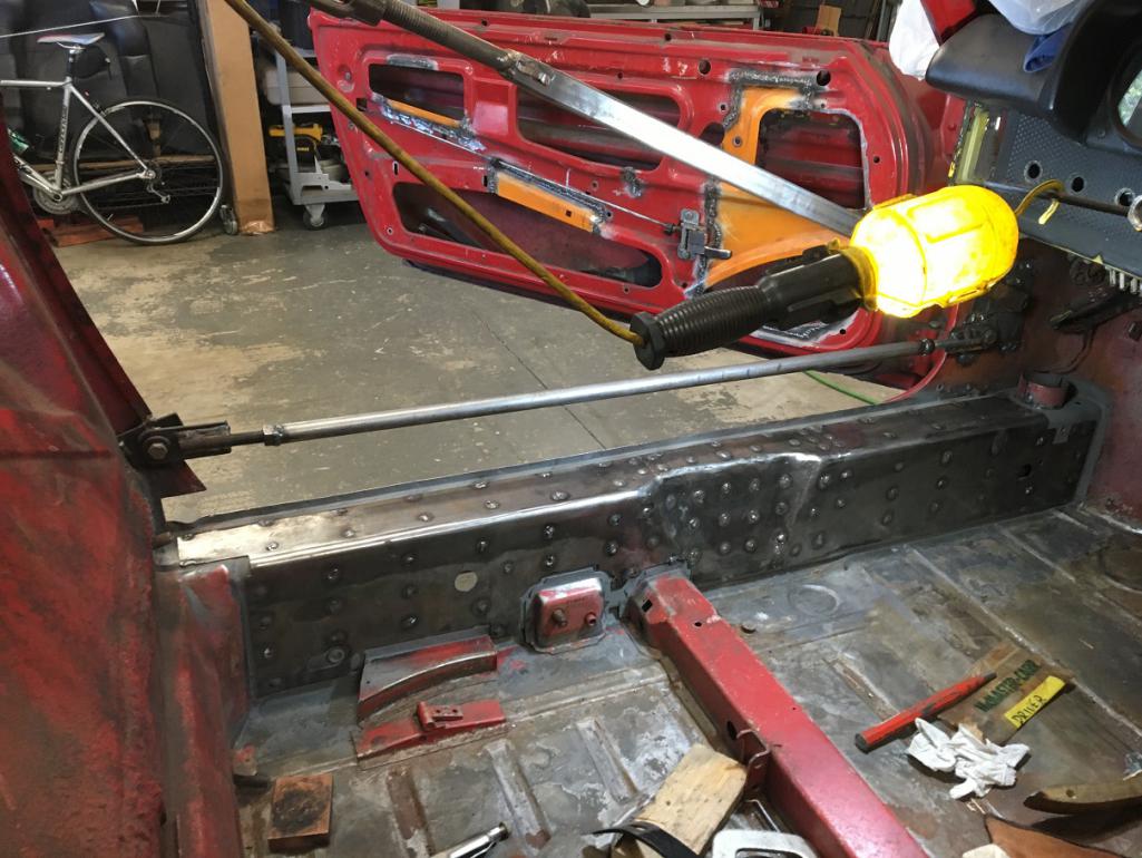 And with welds all ground smooth... I did later add spaced stitches around the perimeter, but you get the idea... 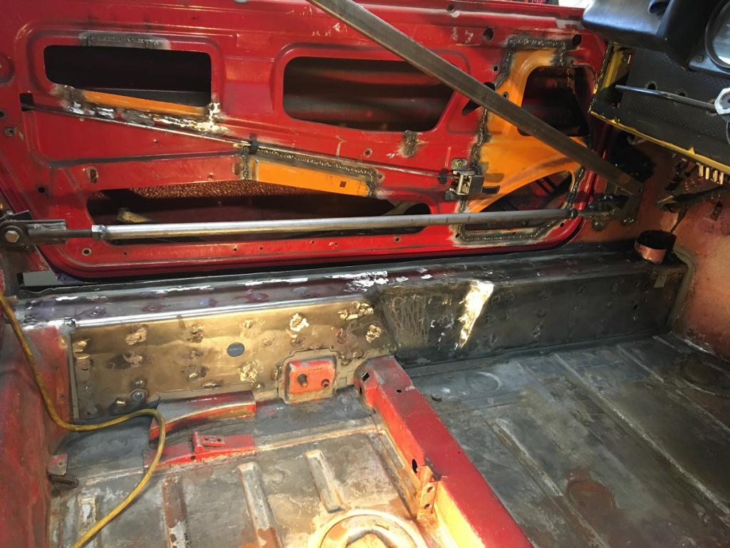 Next step, still working on the inner side of the long but at the engine mount area. This car now being a six conversion, it will not need the body engine mounts on either side. Once removed, I plan on reinforcing the area. (IMG:style_emoticons/default/smash.gif) Now you see an engine mount. 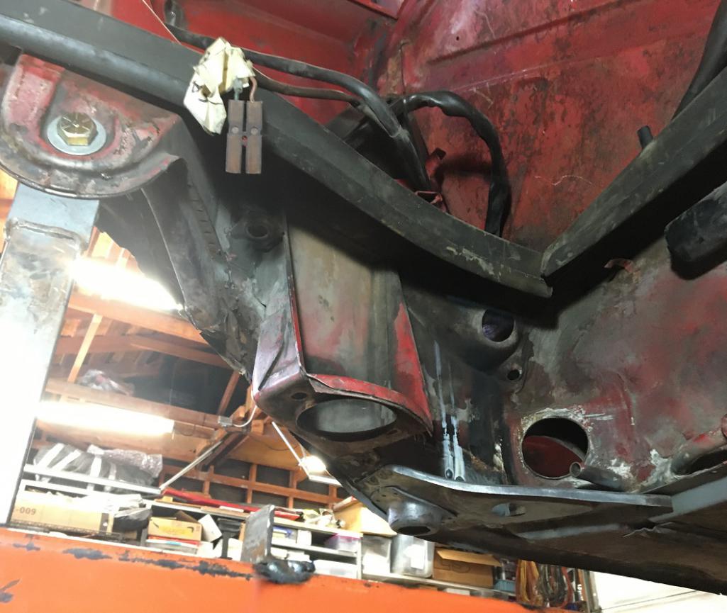 And now you don't! (IMG:style_emoticons/default/smile.gif) You can also see that oval double layer I had installed in post #158 in the indent. 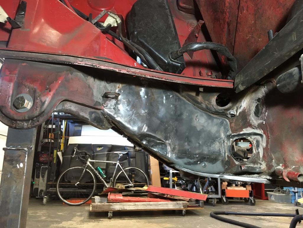 I decided to reinforce the elbow area of the long tying the boxed firewall area to the susension console. Using a portion of a Maddogs inner stiffening panel, I shaped it to fit the beam. Prior to this I had to remove the triangle/donut I had recently reinstalled. (IMG:style_emoticons/default/headbang.gif) The good news it that I can clearly say, my weld were good as it was a bit of a pain to get it off... 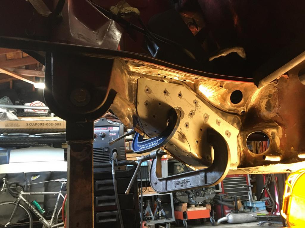 Reinforcement piece prepped. (IMG:style_emoticons/default/smile.gif) 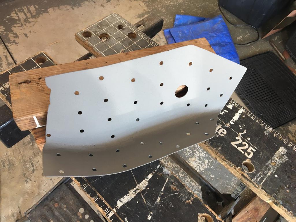 Continuing on next post... |
|
|
|
| Montreal914 |
Aug 9 2025, 02:42 PM
Post
#174
|
|
Advanced Member Group: Members Posts: 2,075 Joined: 8-August 10 From: Claremont, CA Member No.: 12,023 Region Association: Southern California |
...And prepping of the long itself.
 Ready for welding. (IMG:style_emoticons/default/welder.gif) Welding upside-down is no fun though... (IMG:style_emoticons/default/wacko.gif) 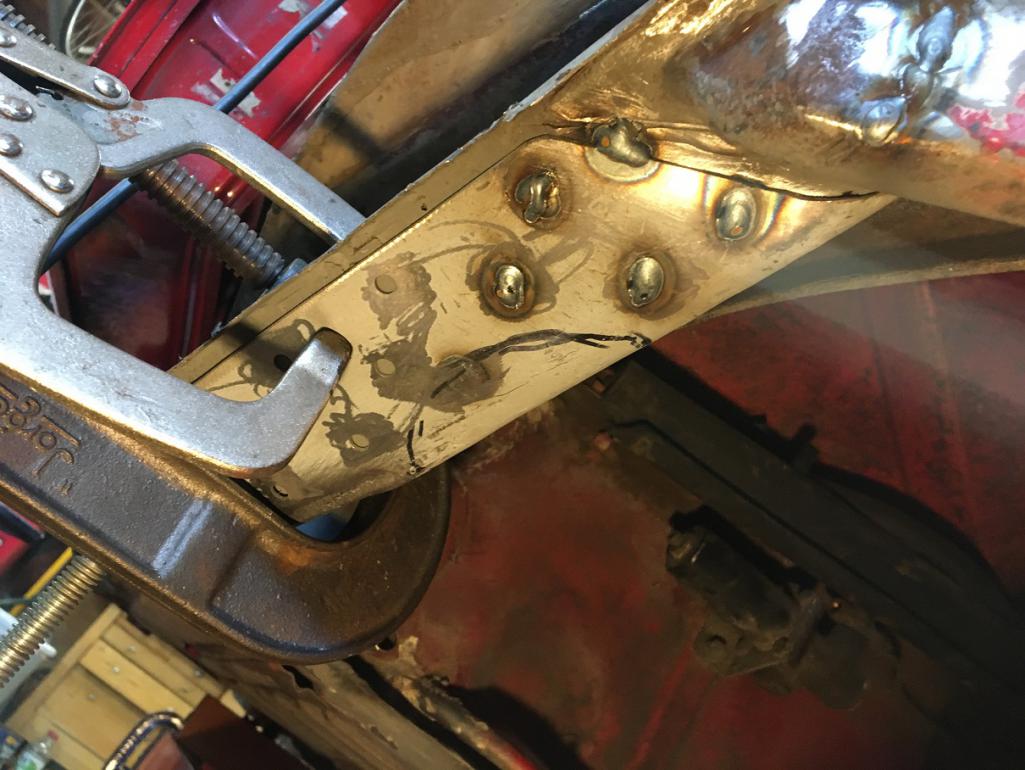 Once all welded in. (IMG:style_emoticons/default/beer3.gif) Notice the photographic art feature in the background... (IMG:style_emoticons/default/biggrin.gif) 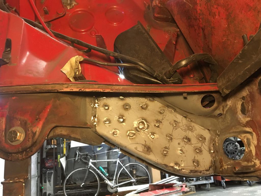 Next; welding back the brake line bracket and the triangle/donut piece. (IMG:style_emoticons/default/smash.gif) |
|
|
|
| Cairo94507 |
Aug 10 2025, 07:05 AM
Post
#175
|
|
Michael Group: Members Posts: 10,610 Joined: 1-November 08 From: Auburn, CA Member No.: 9,712 Region Association: Northern California |
Excellent work and great shot with the 6 in view. (IMG:style_emoticons/default/beerchug.gif)
|
|
|
|
| nivekdodge |
Sep 30 2025, 08:56 PM
Post
#176
|
|
Member Group: Members Posts: 332 Joined: 28-August 21 From: Pittsburgh Pa Member No.: 25,860 Region Association: MidAtlantic Region |
I see what you did there.......
|
|
|
|
| friethmiller |
Oct 1 2025, 05:39 AM
Post
#177
|
|
Senior Member Group: Members Posts: 1,214 Joined: 10-February 19 From: Austin, TX Member No.: 22,863 Region Association: Southwest Region |
Very nice! I enjoy fabrication the results in a better ride (IMG:style_emoticons/default/driving.gif)
Keep up the great work, Eric. (IMG:style_emoticons/default/popcorn[1].gif) |
|
|
|
| Montreal914 |
Oct 17 2025, 03:19 PM
Post
#178
|
|
Advanced Member Group: Members Posts: 2,075 Joined: 8-August 10 From: Claremont, CA Member No.: 12,023 Region Association: Southern California |
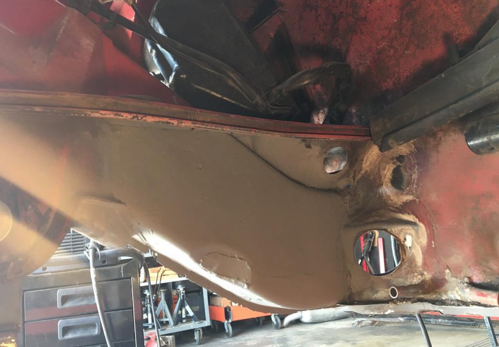
More update on the past weeks work. (IMG:style_emoticons/default/smash.gif) (IMG:style_emoticons/default/welder.gif)
Removing the 4 cylinder engine mount on the body required to remove the brake line bracket for access purposes. Now being reinstalled. The tub is currently leveled, which can be usefull for any other referenced installation (note the small level) 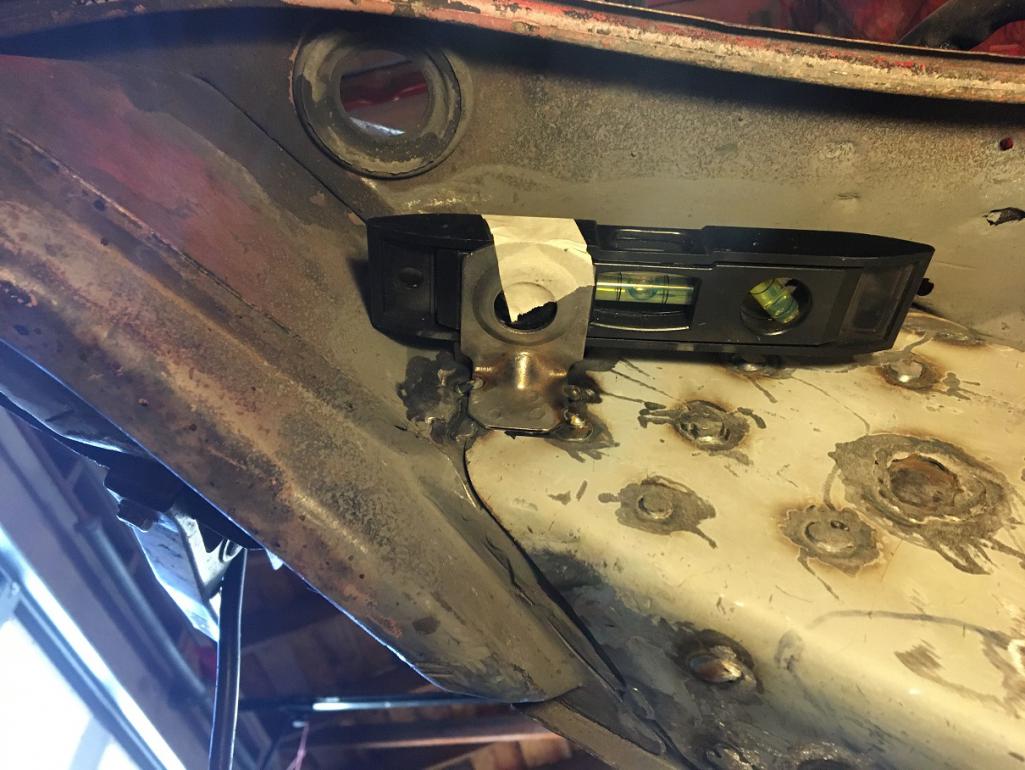 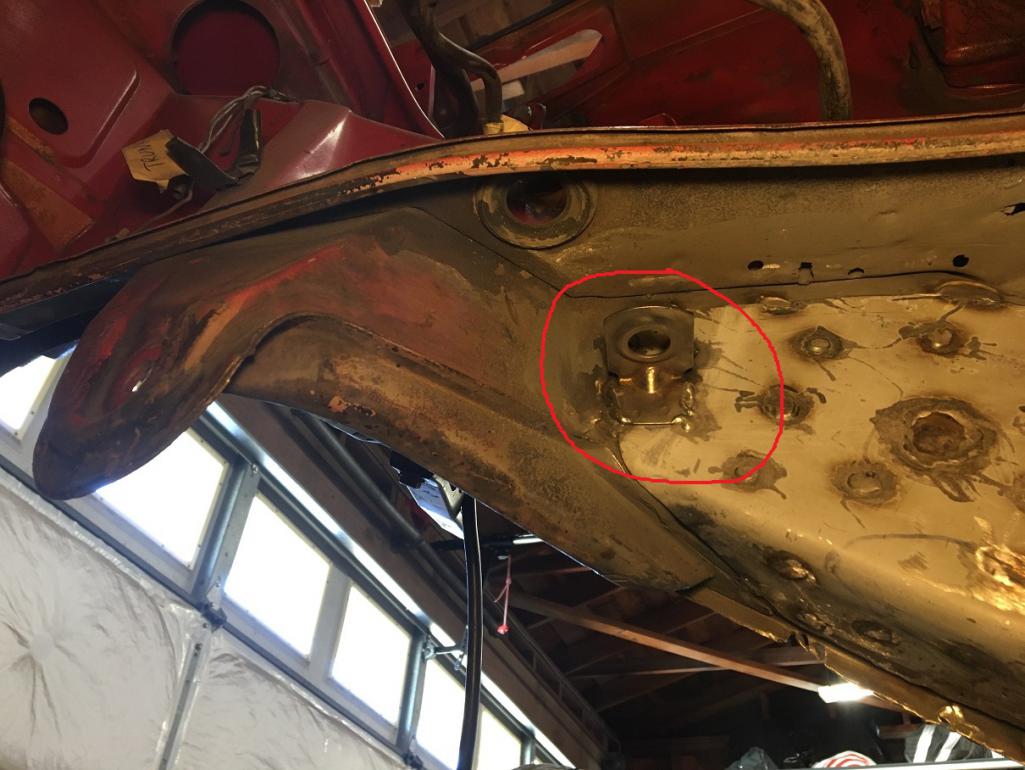 Now moving to the front area under the door post. The removal of the Brad Mayeur repair panels in april of 2023 (post #111) left a scar on the backside of the outer box at the bottom of the door post. Time to fix it. (IMG:style_emoticons/default/smile.gif) Rear section of the box was cut clean and repair piece prepared. 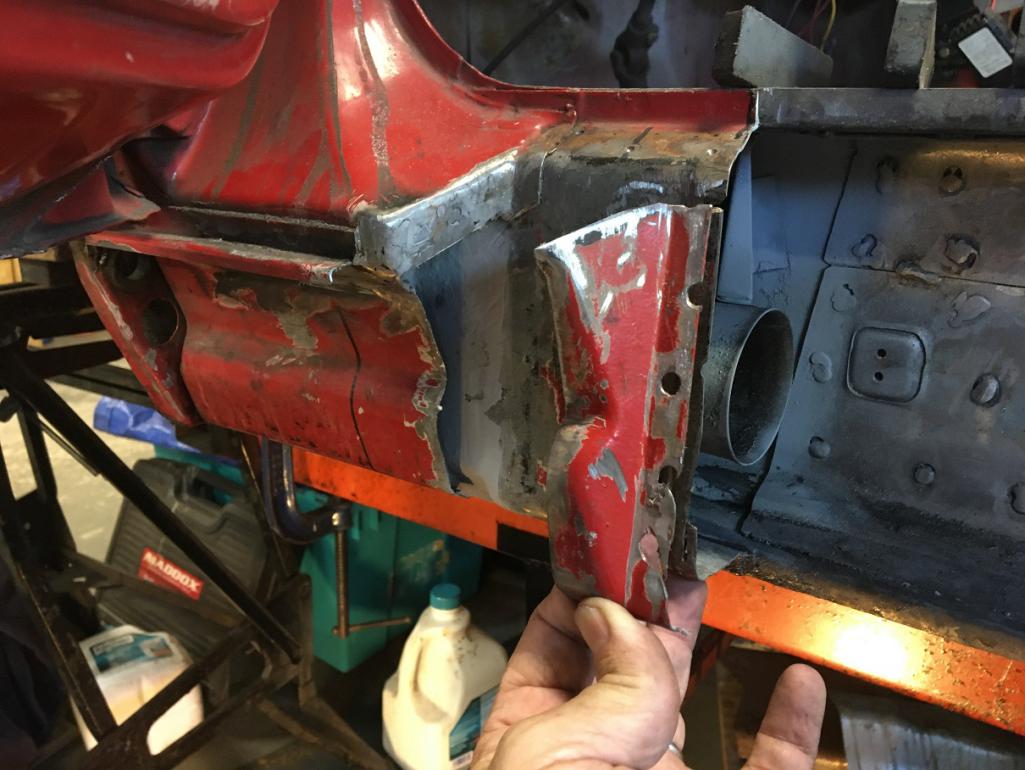 Now tacked in place. 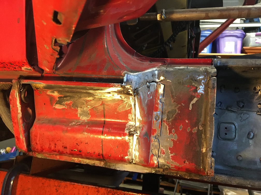 Now fully welded and partially ground. Next up is the planning of the front joint between the tub and the replacement outer cover of the long which I believe is called the inner rocker. Following Jeff Hail's recommendtion in his "Bringing out the dead" thread, I try doubling up any structural joints. Below are the couple of pieces I have prepared and will be set on the back side, then plug welded, you can see the holes prepped. 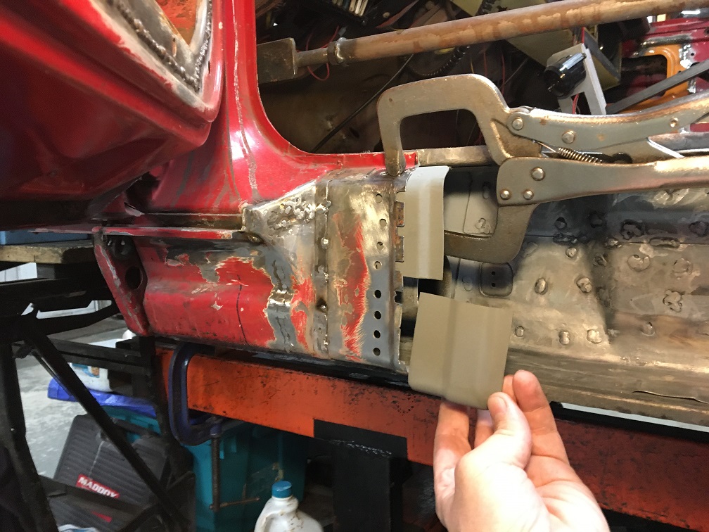 Both pieces installed. (IMG:style_emoticons/default/welder.gif) Now the inner rocker will have a nice lap joint similar to its factory joint in front of the jack post pyramid. 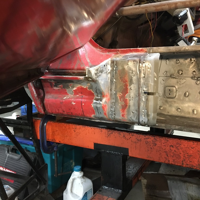 Next up is the rear heating elbow that was removed for access. Time to reinstall it, but first, cleaned up and painted. 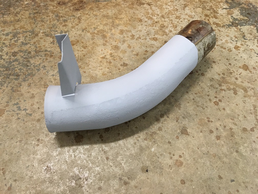 Now installed at its original location. A small portion of its mounting tad had been voluntarilly left attached to the upper inner portion of the long, so I just butt jointed it back. 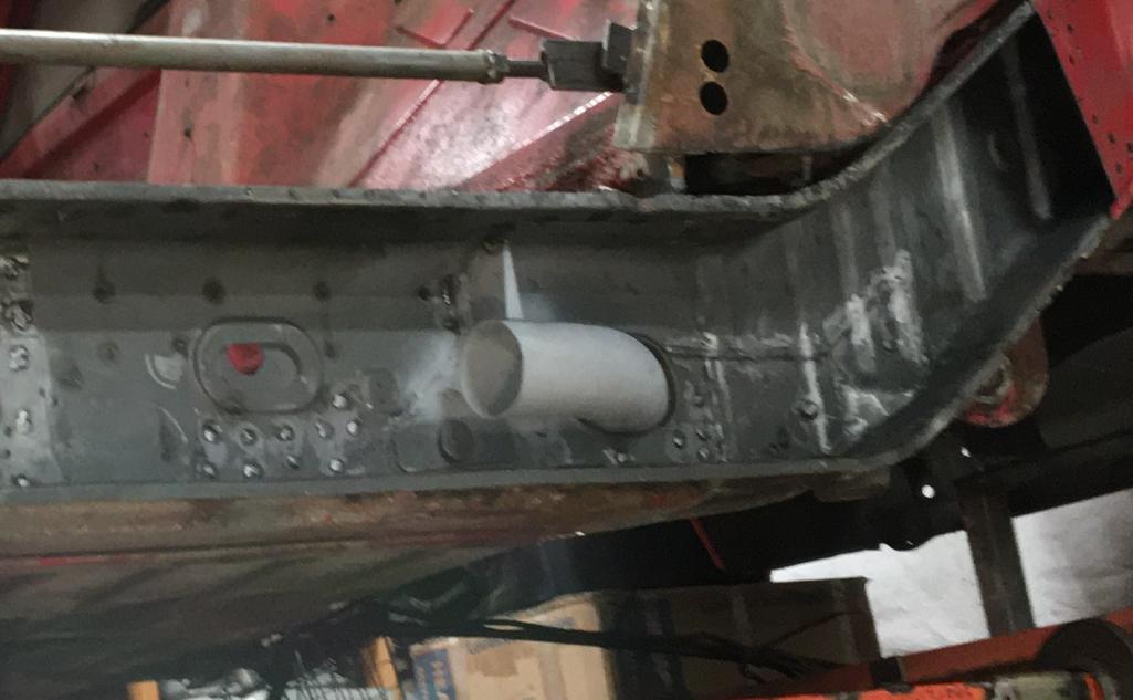 Next moving to the back again. To install the reinforcement piece on the long elbow in the engine compartment side, I had to remove the donut triangle for the second time... (IMG:style_emoticons/default/rolleyes.gif) Anyway, I repaired it for the second time due to removal damages... 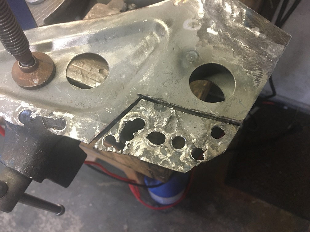 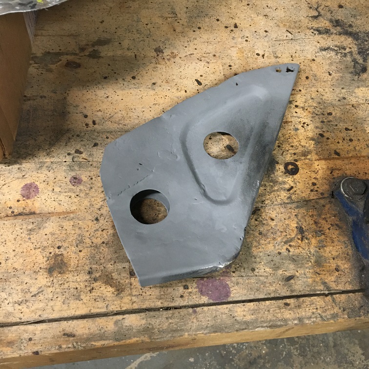 And then welded it to the chassis. Upside down welds are always fun... (IMG:style_emoticons/default/rolleyes.gif) I did find that increasing the power and the wire feed helped a lot. I was actually pretty happy with those plug welds. 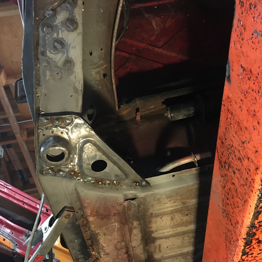 And one last one from inside the engine bay. Not much light though... 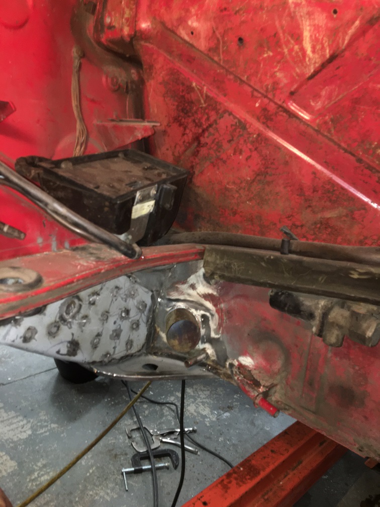 At this point I am almost done with the inner half of the long and will soon be working on closing it up. More to come! (IMG:style_emoticons/default/smile.gif) |
|
|
|
| Root_Werks |
Oct 17 2025, 04:14 PM
Post
#179
|
|
Village Idiot Group: Members Posts: 8,932 Joined: 25-May 04 From: About 5NM from Canada Member No.: 2,105 Region Association: Pacific Northwest |
|
|
|
|
| trojanhorsepower |
Oct 17 2025, 05:47 PM
Post
#180
|
|
Senior Member Group: Members Posts: 1,031 Joined: 21-September 03 From: Marion, NC Member No.: 1,179 Region Association: None |
Great work!
|
|
|
|
|
1 User(s) are reading this topic (1 Guests and 0 Anonymous Users)
0 Members:

|
Lo-Fi Version | Time is now: 7th April 2026 - 06:56 AM |
Invision Power Board
v9.1.4 © 2026 IPS, Inc.