Help - Search - Members - Calendar
Full Version: Rust repair before paint
914World.com > The 914 Forums > 914World Garage
Pages: 1, 2, 3
Montreal914
Edit: I might as well make this my rebuild thread...

Original post; I got side tracked on my Microsquirt build as I have decided, after 11 years of ownership, to finally get my car painted to get her ready for her upcoming 50th birthday. smile.gif
Knowing these endeavors can take a lot more time than initially planned, I hope to make it in time... wacko.gif

Originally bahia red 73 1.7. The goal is a narrow body 2056 Microsquirt, VW Tornado red, 5 lugs conversion with 16" Fuchs.
Front: 914-4 A arms with rubber bushings, 911 3" pin struts, Bilstein inserts, Alfa Brembo, vented rotor, stock torsion bar, 19mm sway bar, turbo tie rods, and 19mm master cylinder.
Rear: Drilled hubs, 914 PMB stock calipers edit: 914-6 calipers replica, 914-6 solid rear rotors, 140lbs springs, stock sway bar, rubber bushings.

But before I get the pleasure of installing all of these beautiful fresh goodies, I need to tackle the not so fun stuff... headbang.gif

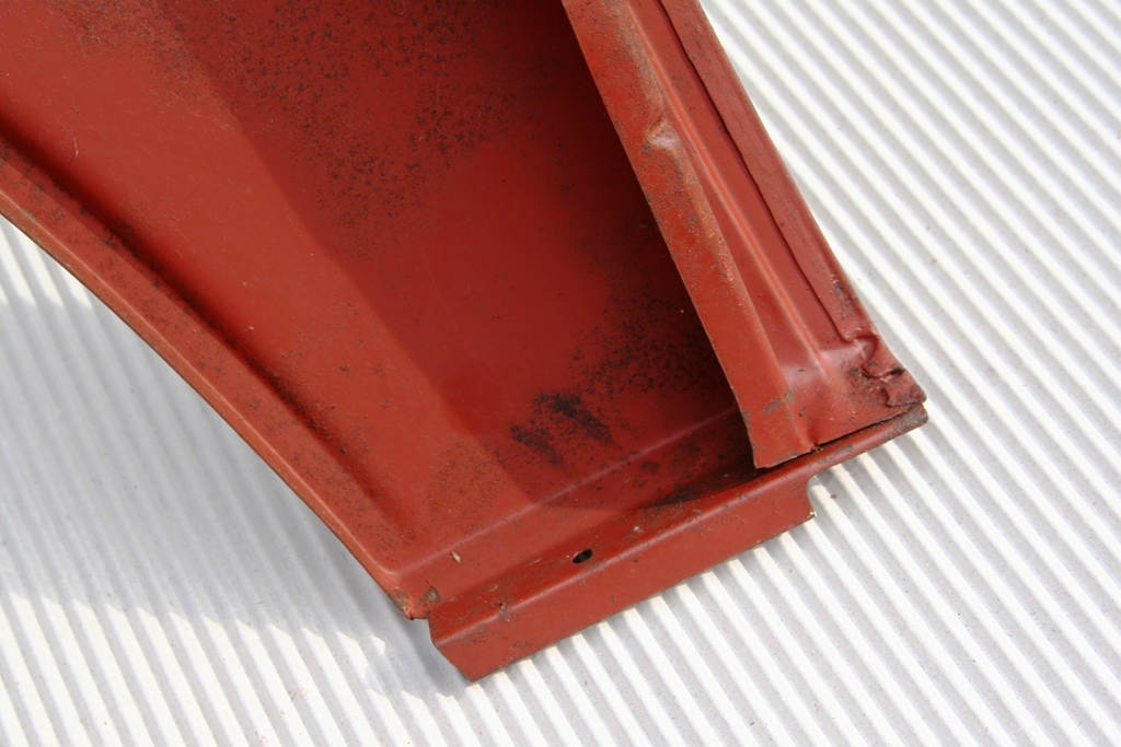
I have already started fixing some of the rust issues and will share that progress in the near future but right now, I wanted to post some of the issues i have on the passenger side front fender. sad.gif I have searched and read many of the builds here but I would like some inputs from the people who have gone through this mess.

I am trying to understand the construction of the rear part of the fender, more precisely the area joining the front cowling.

Below is a sketch of how I think it is made but i would like someone to confirm...

Click to view attachment

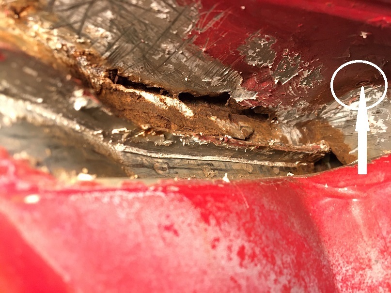
Having removed the seam sealer in the upper rear area, I have discovered "this" dry.gif which is not really unusual, but clearly a pain to fix. I am not sure though what I am looking at. If my sketch is correct, I guess the inner rusted layer is from the fender rear bulkhead that actually becomes an inner layer on the rear upper point of the fender by the door and cowling junction.

Click to view attachment

Click to view attachment

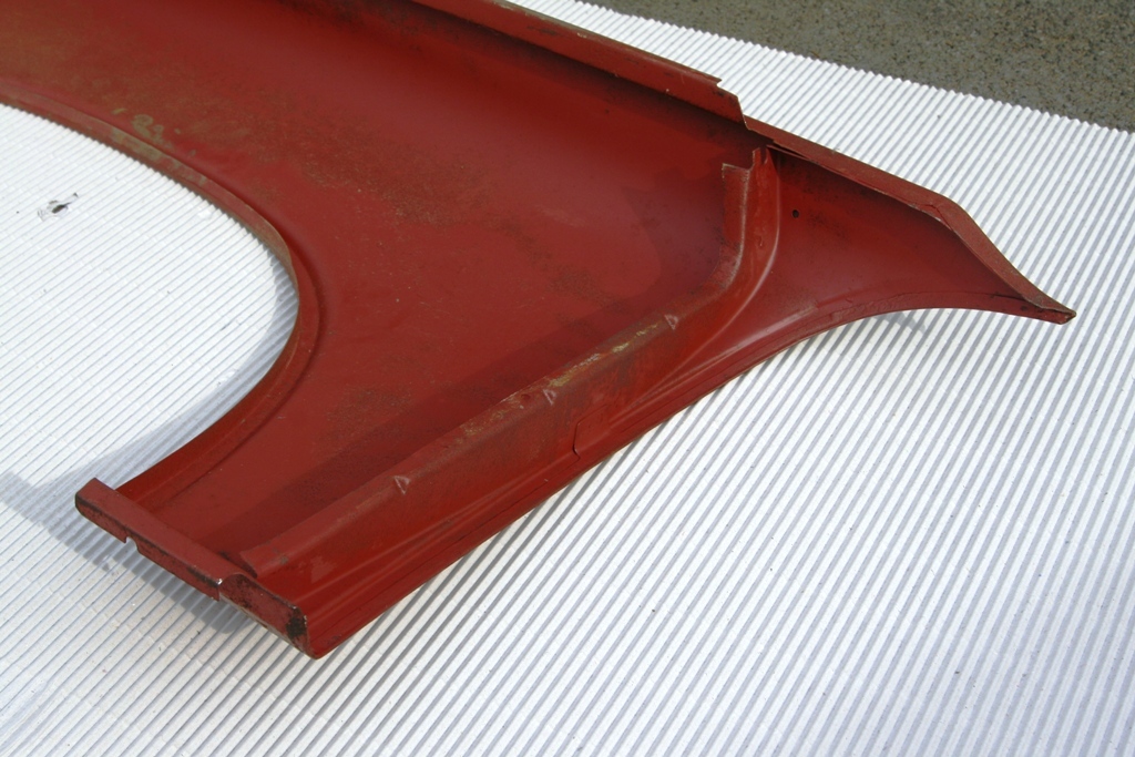
I might be able to cut this from the underside preventing me from cutting the outer surface of the fender. But I would like to better understand what is happening at the junction to the body.
How many layers are there from the fender, one or two?
Is the metal peeling off at the joint to the body the metal from the bulkhead/inner layer, or is it the outer fender layer?

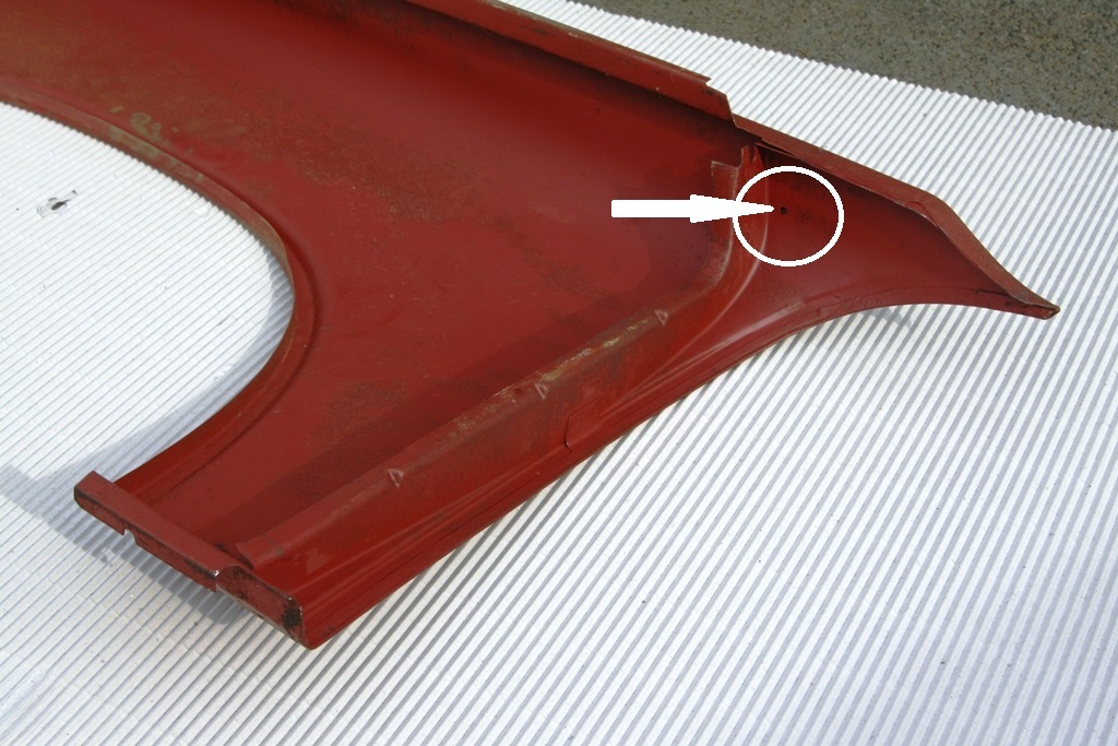
As a reference, this if the situation of the channel, surface rust, but how bad? Is there a way to better know without destroying? Maybe poke with a screwdriver? confused24.gif

Click to view attachment

Comments appreciated smile.gif
horizontally-opposed
All I can say is…go the distance in that area.

A good metalworker thought he had it—but we had to repaint that side of the car. That was after another good metalworker opened up a window in that spot to "really fix it." Well, there's something going on under the paint again.

It's minor, but we all know what it means… barf.gif

If I ever go in there again, I'd really look at not only eradicating all rust with new metal, but what might be done about keeping water out and help find a good drain path for any future moisture that does manage to get into that area.
Montreal914
@cary
Thank you for the links, this is very informative. I wish I had a super in law! smilie_pokal.gif This ought to be interesting and definitely challenging.

@horizontally-opposed
Pete you car has been my inspiration since the first time I saw it parked by the fence at Luftgekült in Long Beach, not knowing it was yours. I was amazed how good the Bahia red could look, compared to my burned and faded one. Immediately after, I inquired here about the nice red car parked by the fence, and found the whole story. It was settled, VW Tornado Red, it was going to be. smile.gif
cary
I'm going to ask George (AA) and Alex and Pete at RD about making another patch panel. George made the cowl piece, we need the fender section too.
I think I've done 4.
I bought a complete hinge post with fender support and harvested the inner piece. But it would be nice to use new metal. Sitting here thinking if I was to do it again and bought another hinge post I'd take it and have it dipped.
Montreal914
Today's update. After carefully studying Cary's pictures smilie_pokal.gif I dove in sawzall-smiley.gif

No big surprises here.

Click to view attachment

Click to view attachment

Click to view attachment

At his point the cowl corner needs to be addressed at the fender junction, at the front trunk seal, and under the windshield area. I think my best bet is to get both or these replacement parts as a foundation for the repair.

Any comments one the fit of these?

Click to view attachment

Click to view attachment
cary
Looks good. Full speed ahead.
I didn't know George even made that piece. Not in Body Sheet Metal section.
I'll do some digging. Lionel has it in their Ebay store.
Montreal914
On AA website:

Part number: 91450303211A and 914503057R

Question is should I put a few patches taken from the repair piece or cut a lot of the car to fit the repair piece as a whole... idea.gif

There is still a lot of good metal on the car in that area. I fear going into the A pillar. sad.gif
cary
Only cut out what you need too on either piece .............
Next big issue is making sure you have the correct gap between the 2 pieces, so the cowl trim strip fits correctly. On Doug's I had about 10mm ( don't know where that came from, we were about 1mm too tight ) that was too tight.
But we made our own pieces by hand.

http://www.autoatlanta.com/results.php?par...r=914%201970-76

Only one piece correctly categorized. I'm going to buy one of each of the fender portions. Already have a pair of the cowl sections.
Montreal914
Yes, it's all about the gap and its evenness throughout its whole length. From the driver's side, it looks like ~3.2mm, which happens to be spot on 1/8" flats.

Will contact AA tomorrow and place an order.

Thank you, will cut only the bad stuff and patch using what is required from new panels. beerchug.gif

Click to view attachment
Montreal914
I worked a couple of hours last night and began to look for solid metal at the junction of the fender with the cowl.

This is after a cut below the fold of the cowl. If I need to go above it I will, but I would rather weld-in the new piece in this hidden area.

Click to view attachment

After the rusted metal was removed, I now have a decent shelf for the new piece to rest on and a nice clean metal in the vertical section of the cowl joint to the fender. Obviously, there will be more prepping before reconstruction.

Click to view attachment

Click to view attachment

Montreal914
A little more cleaning up tonight. Looking at the situation I am considering 2 options idea.gif but which one would be the best... confused24.gif

@cary I really value your advice. What would you recommend? Cutting across per dashed line, or a patch work?

For the patching option, the trunk seal area would get cut out the same way as the fender to cowl to hide the weld. In the windshield area I have to go on the finished surface sad.gif , unless I Ospho the surface and do the cut in an area where the windshield trim will hide the welds, but that seems like a half job since I am already way deep in this. sad.gif

Comments appreciated beerchug.gif

Click to view attachment

Click to view attachment
Arno914
Hi,

here are pics of a NOS Fender I aquired a long time ago. Maybe that helps to understand the construction.

Greetings, Arno

IPB Image

IPB Image

cary
I'd wait till you have the new patch panel in hand. To verify mold and size.
I'd take the section that attaches to the windshield frame out with a couple more cuts.
That way you can lightly touch the spot welds on the glass channel with the right angle die grinder and peel them back.

Click to view attachment

Arno914
Thanks to the detailed pics from Montreal914 I noticed that little hole underneath the fender. Looks like an ideal access for rustproofing the otherwise not reachable area between the fender walls.

I will give this area a good treatment with "Fluid Film". dry.gif

IPB Image

IPB Image
Montreal914
@cary ; Thank you for the input, that second cut will definitely help the removal of these spot welds on the windshield frame smile.gif I am looking forward receiving the sheet metal to compare with the original. What I don't like about the cross cutting of the cowl (dashed line) is that I will loose many references. The little fold that I have left out by cutting below the finished surface still keeps things located.

@Arno914 ; Thank you for sharing the pictures of that beautiful fender. Yes, this will be of great help on the details, especially since there is no seam sealer anywhere. drooley.gif I do have to tackle the bottom end of it too... rolleyes.gif but one nightmare at a time. I have very limited experience in this type of work, but luckily, the help on this forum is simply the best. smilie_pokal.gif
Montreal914
Did a little work this WE. I removed some metal in the windshield corner area while waiting for the repair sheet metal that should arrive Wednesday. I still haven't removed the pitted area, but I am leaning towards cutting the solid marker line, not the dashed one in hope to better keep the overall line of the cowl.

We can see the factory reinforcement layer in the windshield frame corner. I didn't touch that piece, the cut is factory.

Click to view attachment

Then I removed the rusted metal in the cowl corner to the trunk seal area. This is basically ready to receive the repair sheet metal piece after some Ospho and protection.

Click to view attachment


I moved on to repair some DAPO chassis weakening done to run the wiring to a very important piece of equipment rolleyes.gif , an amplifier mounted on the bulkhead in front of the tank...

Before;

Click to view attachment

Click to view attachment


Prepared the patches to fit in the 2 holes, file, adjust, try, and again, until good fit...
The bulkhead is actually thin metal ~0.030" while the back side of that beam is closer to 16 ga. Luckily, I had pieces of metal of the same thicknesses. smile.gif

Bulkhead layer patched:

Click to view attachment


Then the back side (tank side) of the cross beam piece.

Click to view attachment

Click to view attachment

Small steps... smile.gif


Montreal914
Yesterday I received my sheet metal repair pieces, the cowl and rear top fender parts.

The cowl piece is pretty nice and I am still wondering what should be my best approach with this. I can keep as much original metal to the car and cut all up the repair panel to patch the various areas, Or cut straight across the car's cowl and install about half of the width of the repair piece. idea.gif

Here are a few pictures of the cowl piece.

Click to view attachment

Here we can see that hey could have been more generous on the front fold for the trunk seal. I will need to extend that lip a little.

Click to view attachment

Last one showing the line where I could cut the new piece to repair the damaged sections of the car, otherwise, just use the left (car orientation) half of the repair piece and cut the car up.

Click to view attachment


Moving on to the fender repair panel. This one is made for Auto Atlanta but is not the same quality as the cowl piece. The part was bent of hit or something as you can see. Also, the curved outside edge that will create the door gap is not folded. This will be a challenge (at least for me) to fold while creating the proper curve that will define the front top door gap.

Definitely open to suggestions here...

Click to view attachment

Click to view attachment

In this angle you can see the damaged area of the part which lifts up the back side of it... dry.gif

Click to view attachment


I would like to tackle the cowl repair this weekend, but before that, I need to decide how. headbang.gif

Open to comments/suggestions. Thanks! beerchug.gif
cary
Your now into what we/I call the art of massaging patch panels. Almost all need
tuning.
Give us a shot of the fender patch flipped over.
horizontally-opposed
QUOTE(Arno914 @ Oct 28 2020, 01:03 AM) *

Hi,

here are pics of a NOS Fender I aquired a long time ago. Maybe that helps to understand the construction.

Greetings, Arno

IPB Image

IPB Image


It sure does—to the point I am pretty sure I know what the problem with my fender was, and maybe still is, now.
Montreal914
@Cary

Here are a few pictures of the fender patch underside.

Click to view attachment


Here we can see the dent, near us to the left 1/3 in the picture, causing the back end to lift up. I don't think the 2/3 area is dented, just the fold creating this shadow.

Click to view attachment


The lines are pretty good when looking a the original piece I removed from the car. Just wished they had folded the door gap edge...

Click to view attachment


Any final recommendations on the cowl piece? Either I cut across, which minimizes the amount of welding, but there is a risk of trunk line "breakage", or I replace only what is damaged on the car which keeps both the trunk line and the cowl to fender line as i would be welding the new material to unexposed surfaces. Then again, I do need to replace some of the top surface in front of the windshield frame creating a weld parallel to the windshield on the finished surface. Maybe this will cause a lot of distortion... headbang.gif

I am ready to go, just need a little hint biggrin.gif All suggestions welcome smile.gif
cary
I'd say do the cowl section first.
Then tune the new fender portion to the new cowl.
As for the new fender section you'll need to create some dolly strips to tune/reshape the tip.
Montreal914
QUOTE(cary @ Nov 6 2020, 01:49 PM) *

I'd say do the cowl section first.
Then tune the new fender portion to the new cowl.
As for the new fender section you'll need to create some dolly strips to tune/reshape the tip.


Yes, cowl first, agreed.

Would you cut across from the windshield frame to the trunk, or do a patch work keeping as much of the original metal.

This is my main hold up right now. Cutting the new piece per my marker lines with multiple welds or just replace a big surface using the left half of the new cowl piece?
cary
Go big. You wouldn't be happy welding that short flange to the step. It would explode.
Anywhere the material gets shaped/stretched it doesn't like too much heat.

Click to view attachment
Montreal914
QUOTE(cary @ Nov 6 2020, 02:24 PM) *

Go big. You wouldn't be happy welding that short flange to the step. It would explode.
Anywhere the material gets shaped/stretched it doesn't like too much heat.

Click to view attachment


Perfect! beerchug.gif

Go big or go home as they say. smile.gif

Will cut the cowl up across and use the new piece. Thank you for the input. smilie_pokal.gif
Next posting will be of this accomplishment... sawzall-smiley.gif welder.gif
Eric_Shea
If you leaf through this album, there's a ton of cowl repair pics. Hope that helps:

https://www.facebook.com/media/set/?set=a.1...8193&type=3

E.
Montreal914
@Eric_Shea Thank you for the link. Very nice pictures and, as expected, beautiful restoration work! smilie_pokal.gif

Time for a little update at my end. Before installing the new cowl repair piece I had to take care of the rusted corner in the inner fender area. I created a little patch that had many corner and struggled with very limited access to install it. Not the best work, but it will have to do... dry.gif Then I prepped the area with weld through primer.

Click to view attachment

Repair piece ready for install

Click to view attachment


After a lot of trial fit and subtle grinding and filing of both the car and the repair piece, it was time to make the big step of installing the cowl repair piece. After a couple of tacks at the windshield area, I wanted to fit the trunk seal area.

Click to view attachment

Then checked the result from underneath and wasn't happy with how this was lining up... dry.gif Time to cut and redo that.

Original attempt
Click to view attachment

Second try
Click to view attachment

Moving on to more tack welding
Click to view attachment

Making sure things are still lined up. Not perfect but I didn't think I had the ability to do better.
Click to view attachment

The front edge was a concern and this is where we can see that the reproduction part is not 100% perfect. I was able to raised it up with light taping from underneath but final body work will need to address that area.

Click to view attachment

Then, slowly fill the voids between the tack weld, one spot at a time... welder.gif

Still have the back edge of the A pillar to complete but this is close to final. As a first attempt to venture into this kind of work I am happy with my accomplishment. Support here was key smilie_pokal.gif @Cary . Hopefully the second part of this repair, fender side, will go well too.

Click to view attachment

Click to view attachment


Montreal914
It has been over two months since I posted some progress, time for some update. Things have been moving along pretty well.

The welds of the cowl piece were grinded down and now ready to move on the fender rebuild.

Click to view attachment

Click to view attachment


The more I was looking at the AA top repair panel, the less I was attracted to use it. So I decided to hunt for and original front fender upper corner that I could use as a whole, both the inner and outer portion. I was lucky to find this one in decent shape that I started dismantling and preparing.

Click to view attachment

The back side is very good looking on the recycled piece smile.gif especially compared to the original portion next to it... rolleyes.gif

Click to view attachment


Now, it needed to be cut down to fit on the car. It was also missing a portion of the trunk seal channel, so a little more fabrication and obviously a lot of back and forth to make sure everything fits perfectly. smash.gif

Click to view attachment

Making progress...

Click to view attachment

Click to view attachment

And, once ready, tack welding, making sure the alignment is good.

Click to view attachment

Click to view attachment

Click to view attachment

Since there was a little step at the door front edge line, I added some metal and refinished the line accordingly.

Click to view attachment

And the end result smile.gif

Click to view attachment

Click to view attachment


mb911
Looks great. That is a spot on my car I repaired and ended up with a bit to much gap.. kinda sucks as the car is all painted now. I wanted to find wider welting to fill the gap..
Montreal914
Moving on to the other problem area of this fender... dry.gif

The typical rusted lower point which is located near the doubled up packed with seam sealer, not very surprising...

Click to view attachment

Again, AA sells a repair piece but I prefer using an original piece and got this one smile.gif

Click to view attachment

After removing all of the unnecessary metal and seam sealer, the parts started to look a lot better.

Click to view attachment


Time to remove the old and replace it with the old.

Click to view attachment

Click to view attachment


Result:

Click to view attachment

Click to view attachment
Montreal914
QUOTE(mb911 @ Jan 24 2021, 04:01 PM) *

Looks great. That is a spot on my car I repaired and ended up with a bit to much gap.. kinda sucks as the car is all painted now. I wanted to find wider welting to fill the gap..


The gap was my concern all along. I am happy with the result, but it is a little wider than before. The Restoration Design cowl piece is very nice, but the radius is larger than stock which is very square. The fender top AA piece has a radius of about 1/8" rolleyes.gif and was way too far for me to use it. That is why I got a piece from an original fender.
mb911
QUOTE(Montreal914 @ Jan 24 2021, 04:10 PM) *

QUOTE(mb911 @ Jan 24 2021, 04:01 PM) *

Looks great. That is a spot on my car I repaired and ended up with a bit to much gap.. kinda sucks as the car is all painted now. I wanted to find wider welting to fill the gap..


The gap was my concern all along. I am happy with the result, but it is a little wider than before. The Restoration Design cowl piece is very nice, but the radius is larger than stock which is very square. The fender top AA piece has a radius of about 1/8" rolleyes.gif and was way too far for me to use it. That is why I got a piece from an original fender.


My issue was the replacement fender I put on.. It didn't fit well in both locations so I opted to make it better on the curvature of the door.. some day I may have a another go at it but needed to progress forward.
Montreal914
Time to switch to the rear fender of that same side. Another classic, the base of the sail panel. There was a couple of bubbles in the paint, so I wasn't surprised to see rust there.
I cut out the bad area and removed the seam sealer packed underneath and around the vent tube.

Click to view attachment


Then, prepared a repair piece and trial fit

Click to view attachment

Weld and finish up. I have to say that after fixing the cowl area, this is easy smile.gif

Click to view attachment

Click to view attachment

Click to view attachment
bkrantz
Nice work--keep it up!
Montreal914
This weeks update:

The door latch bracket deep in the rear fender well needed some help. The cover was rusted on the bottom half. After removing it and threating the area with Ospho, time to start rebuilding.

Click to view attachment


Now with weld through primer and the threaded piece held in place. Good thing i kept on reminding myself to put it there before closing the cover without it, that would have been no fun...

Click to view attachment


For the cover, I elected to make my own with a template I did, shown here on a spare bracket that didn't end up using.

Click to view attachment

Click to view attachment

Click to view attachment

I added a lower opening to spray in some rust protection with a tube later on. Then spray painted with weld through primer

Click to view attachment

Click to view attachment


Then held it in place with my telescopic magnet, ready to stretch and weld it afar with my left hand... rolleyes.gif

Click to view attachment


Moving on to the lower fender corner. The one packed with that darn seam sealer that makes things rust... headbang.gif

First the lower part: Repair piece, welded, then finished...

Click to view attachment

Click to view attachment

Click to view attachment


Then the front part: same process...

Click to view attachment

Click to view attachment

Click to view attachment


Tomorrow, Sunday, day off sunglasses.gif Next weekend, more cut and repair... sawzall-smiley.gif smash.gif welder.gif
Cairo94507
Very nicely done and great attention to detail. beerchug.gif
pencap914
Nice work Eric! Looks like my 914 will need a similar repair at the cowl. It looks like a daunting task, but this thread is giving me some inspiration to tackle it.
Montreal914
Fresh update smile.gif

Spent some time finishing the rear trunk floor replacement. First, cutting the crappy rusted through old piece, removing the cross beam reinforcement middle top plate, and brushing the metal clean.

Click to view attachment

Click to view attachment

Click to view attachment


Weld through primer on the weld surfaces.

Click to view attachment


Then the new floor piece from Restoration Design smilie_pokal.gif was fitted with the original chassis number plate. And no, I will not cut open the round ports since I don't have a spot welder that needs to go through them biggrin.gif . This is a daily driver, not a authentic restoration.

Click to view attachment

Click to view attachment

Using the spot welds on the car's back panel as a guide for the floor height, I plug welded the new panel in, then added the recycled reinforcement plate on the cross member. Done. smile.gif

Click to view attachment

Click to view attachment


Now for the exhaust heat shield, I elected to screw it to the floor with pan head M6 screws. So I drilled holes and welded M6 nuts on the shield's brackets.

Click to view attachment

Click to view attachment


This cardboard template will help me drill the trunk floor in the right spot for the shield's screws.

Click to view attachment
Montreal914
Battery tray! cheer.gif

Some like to weld it in place, others screw it so they can paint the inside of the support. I chose to install it with screws, which was the long route... rolleyes.gif

First, for battery I am using an Odyssey PC925 which is a lot smaller that the stock battery tray. Also, as a requirement from the POC rules, the battery is supposed to be held in place by a cross bar on top. So all this led to this bit of re-engineering of the tray and its support. smash.gif

First let's look at the support. I extended the folds, drilled holes and welded M8 nuts (3) on the backside for the tray to attach to.

Click to view attachment

Click to view attachment


Next the tray was also modified. For the top cross bar, I intend to use 2 M8 treaded rods that will be attached to each side of the tray. The first one will use the nut on the middle of the angle seen in the picture below. The second rod will use the nut where the stock "Z" shaped bracket normally bolts on. Also on the angle, we can see two M8 nuts for through the inner fender anchoring bolts.

Click to view attachment


Here the tray rests on its support with the holes lining up to the nuts on the support underneath. As mentioned, the Odyssey battery is smaller and will actually fit between the heads of the front and back screw, and between the threaded rods that will be on each side.

Click to view attachment


Finally these are the M8 screws through the inner fender

Click to view attachment
Root_Werks
Really like this thread! You've got some skills, inspiring!
Montreal914
QUOTE(Root_Werks @ Apr 26 2021, 02:24 PM) *

Really like this thread! You've got some skills, inspiring!


Thank you. smile.gif I am happy with most rolleyes.gif of my work's results.

Although this is my first attempt in this kind of work, I owe it to my dad who taught me my hands-on and mechanical skills. The year I was born, he began building a trimaran sailboat from a set of Australian plans in hopes of taking us sailing in the Bahamas. 8 years later, in '78, We towed the boat driving from Montreal to Miami, set it to sea and went discovering the Bahamian islands on this lightweight flying machine! In a way, similar ideology with our beloved 914; very light and nimble. sunglasses.gif

Click to view attachment

Montreal914
Now back to the main program...

Removing the carpet on the driver's side long, I noticed the classic crack on the hand brake area. The car currently has a Brad Mayer stiffening kit on the outside.

Click to view attachment

What is the recommended method to fix this? Simply weld up, cut the area and replace with fresh metal, weld and double up with a extra layer? confused24.gif
bbrock
I just got caught up. Fantastic work. I'm enjoying getting to ride along.

Now I have to ask, where is that boat now? That is epic!
Montreal914
QUOTE(bbrock @ May 1 2021, 05:02 PM) *

I just got caught up. Fantastic work. I'm enjoying getting to ride along.

Now I have to ask, where is that boat now? That is epic!


@bbrock ; I am not sure of the current condition of the 24' long x 19' wide little trimaran made out of 3/16" thick plywood. I will ask him if he has fresh news from the new owners. In the early '80s, my dad traded it with extra money for a home built fiberglass foam sandwich 39' x 20' catamaran with a 45' mast from the same Australian designer. That one weighted 8,000lbs, which is still very light weight and very quick for that size sail boat. We enjoyed it as he improved it over the course of many years. He sold it a few years ago, as the maintenance and the navigation became too much for my parents who are now in their 80s. Below, picture taken in 2009 of him with our two daughters, a few month before our move to California. This was on lake Champlain upstate New York near the Canadian border.

Click to view attachment


All this nautical distraction is very nice, but we are here to share about 914s biggrin.gif

So, what is the consensus on fixing the crack on the driver side inner long... idea.gif
bbrock
Thanks for the update on the boat(s). Fantastic.

As for the crack, I'd say just weld it up, especially with the stiffening kit. I had to replace that whole bottom section on mine due to rust. I figure by the time it cracks again, I'll likely be long departed.
Montreal914
QUOTE(bbrock @ May 1 2021, 09:18 PM) *

Thanks for the update on the boat(s). Fantastic.

As for the crack, I'd say just weld it up, especially with the stiffening kit. I had to replace that whole bottom section on mine due to rust. I figure by the time it cracks again, I'll likely be long departed.


Yeah, I will do that and maybe add another layer with plug welds. Thanks! beerchug.gif
Montreal914
Wow, already about 3 1/2 months since my last post! sad.gif

Well, there was some progress but not as much as I would have hoped for.

Next on the list are the trunk hinge base mounting points. The left side one had the captive cylindrical nut detached from the base, and the right side one had been rewelded in the course of the car's life, but not in the correct location. dry.gif


Removal of both sides:
Click to view attachment


Repair the holes:
Click to view attachment


The new hinge base have a couple of good tacks on the back side for the cylindrical nut. But I decided to add some more on the front side... biggrin.gif
Click to view attachment


To make sure the new hinge were installed in the right location, I placed the trunk lid on the car, and using sockets as shim in all four corners I adjusted the height and gaps. I also made cross marks on tape to easily reposition it later.

Click to view attachment


Once happy with the trunk lid alignment and fit, I screwed in the hinge base to the trunk hinge bracket with a new shoulder bolt and marked where it would be set on the body.

Click to view attachment


After marking both hinge base to the body, I removed the trunk lid, installed the hinge bases with self tapping screws and installed the lid again for final verification.

Click to view attachment


Measure twice weld once rolleyes.gif welder.gif

Click to view attachment


Third trunk lid test install, everything operates smoothly and lines up nice. smile.gif No picture but you get the idea.


Montreal914
Time to move on to the engine lid, which also needs help... smash.gif

Typical 914 engine lid bracket issues, both have been repaired, but the passenger side one is broken again. dry.gif

Click to view attachment


I got a pair of original brackets at one of Bruce Stone's swap meet a while back knowing I was going to need them.

These typically fail in two ways:
1- at the bend (like mine)
2- detach from or rip the firewall.

Thinking of ways how to prevent this to happen again, at least problem #1, I did this little clearance study:

Click to view attachment

Click to view attachment

Click to view attachment


Clearly, there is room on that "L" bracket to add a gusset on each side making it a lot stronger.

So here we go! smile.gif

Click to view attachment


Once done:
Click to view attachment


After a little trimming and adjustment, here is the updated clearance study: smile.gif

Click to view attachment

Click to view attachment

Click to view attachment


I am pretty sure this is the end of the bracket cracking problem! sunglasses.gif


Here the rebuilt bracket is welded to the firewall on the sides catching more of that embossing. Hopefully, this will also prevent problem #2 explained earlier. That being said, all of these issues can probably be avoided by holding the engine lid as it is being released. An easy good habit that many of us have very early on adhered to for obvious reasons. smile.gif

Click to view attachment


Not shown, but the engine lid was properly aligned to the body in order to set the "L" bracket in the right location on the firewall.


Montreal914
Wow it has been many months since I have updated this thread. sad.gif The good news it that I did make progress! smile.gif

Planning ahead, I am doing modifications to the oil network. Although this is a 4 cylinder car, I intend to stroke my current 2056 to a 2258 (2270) in the future. So I already have made changes on the engine side as described in this halted (for this body work) Microsquirt thread:

Post #46 here: http://www.914world.com/bbs2/index.php?sho...42361&st=40

I made an aluminum panel for the remote oil filter and thermostat. I will be using a rabbit/jetta diesel filter which is rather large (almost 1 quart).

Click to view attachment

I welded 4 cylindrical tapped standoffs (911 part) to the lower right portion of the firewall to mount the assembly. The filter is high enough to be fully protected. The oil lines from and to the engine will connect in the middle area of the assembly, while the lines to the front cooler connect to the right side of the thermostat. This also clears the heating flexible tube between the heater valve and body heater duct.

Click to view attachment

More to come... stirthepot.gif
Montreal914
Between the filter/thermostat assembly and the front cooler, I plan on routing the lines along the outside of the passenger long. About 10 years ago, I fitted the car with a Brad Mayer reinforcement kit which actually butts in on the back side of the tapered box in the front of the long. Since it sits away from the outer long of about 3/8", it is obstructing some of the box' backside preventing me from drilling holes large enough to run the lines through the box à la Elephant racing hard lines. Therefore I had to create a channel in the box to make room for the lines.

Here is the box with the reinforcement kit butting on its back side:
Click to view attachment


Now the box has been opened up with the removal of the lower front corner that was rusted:
Click to view attachment

Patching the corner:
Click to view attachment

And now putting back the lower front part of the box leaving a trench for the lines to go through:
Click to view attachment

Finally, after shaping the trench from a flat sheet, I closed up the box to keep some structure integrity. Shown here with my line mockup:
Click to view attachment

Next, the jack point pyramid had to be trimmed for the same purpose. This pyramid is part of Brad Mayer's kit and is made of thick steel:
Click to view attachment

At this point the path is clear to run the oil lines along the passenger side longitudinal beam. smile.gif
This is a "lo-fi" version of our main content. To view the full version with more information, formatting and images, please click here.
Invision Power Board © 2001-2024 Invision Power Services, Inc.