|
|
|
Porsche, and the Porsche crest are registered trademarks of Dr. Ing. h.c. F. Porsche AG.
This site is not affiliated with Porsche in any way. Its only purpose is to provide an online forum for car enthusiasts. All other trademarks are property of their respective owners. |
|
|

  |

| Ron914 |
 Oct 18 2025, 01:43 PM Oct 18 2025, 01:43 PM
Post
#181
|
|
Member  Group: Members Posts: 492 Joined: 19-April 22 From: Huntington Beach,Ca Member No.: 26,487 Region Association: Southern California |
Coming along nicely Eric . I look forward to a spirted ride across Angeles Crest Hwy one day .
|
   |

 
|
| Montreal914 |
Oct 18 2025, 09:42 PM
Post
#182
|
|
Advanced Member Group: Members Posts: 2,075 Joined: 8-August 10 From: Claremont, CA Member No.: 12,023 Region Association: Southern California |
After looking at everything, I believe I am close to paint the inside of the inner longituginal beam. It is a good feeling!
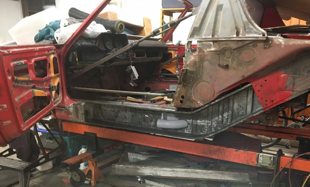 And a final look up the back. 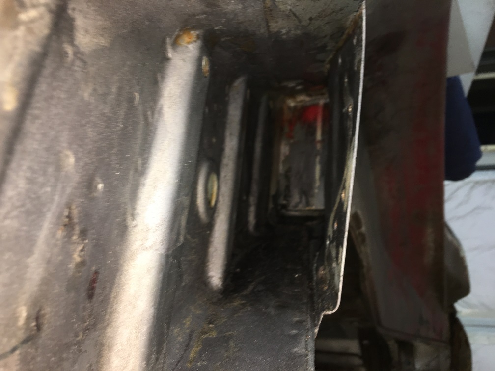 Prior to do so, the entire surface was treated with Ospho and let dry. This makes the bare steel gray with this white dusty texture. It feels like a good protection. I read that some epoxy primer have issues adhering to an Ospho treated surface. I followed the instructions on the bottle. After drying. I thoroughly wipe the surface with mineral spirits 2-3 times and let dry. Then, I applied Rustoleum primer sealer which is oil based, again correlating with both the Ospho and mineral spririts instructions. Is this the best option? I don't know, but surely, this car's second life will be alot milder than its first. I am also thinking about spraying cavity wax in there, but only after the car will be painted. Now painted. (IMG:style_emoticons/default/smile.gif) (IMG:style_emoticons/default/beer3.gif) (IMG:style_emoticons/default/beer3.gif) 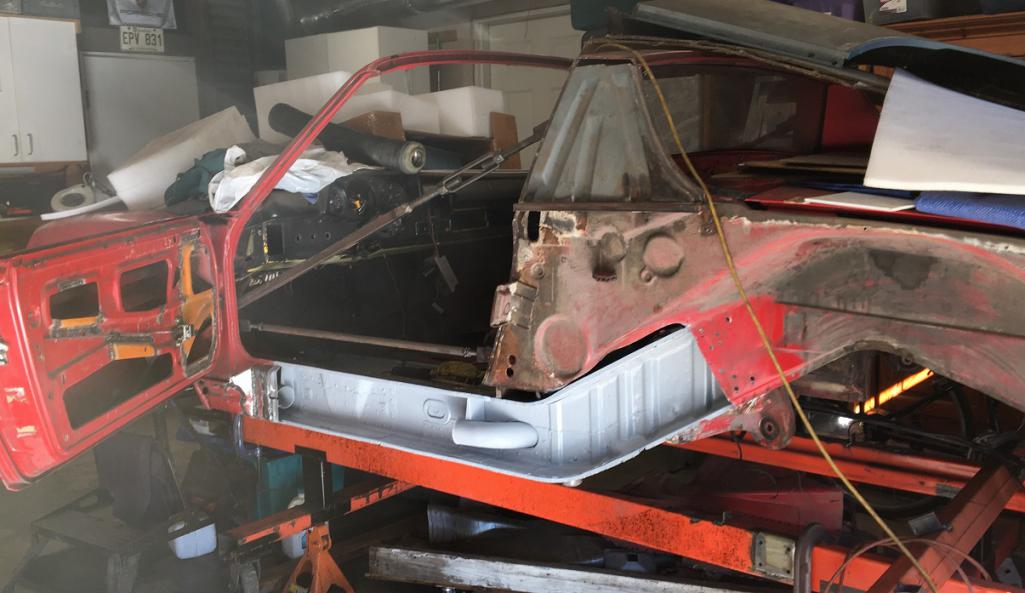 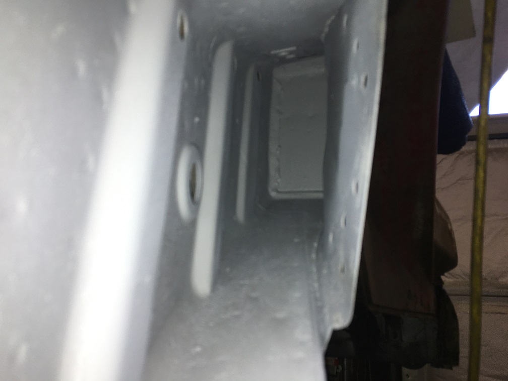 With the can out, I prepped the heater tube spring clamp, then shot them with the primer sealer. 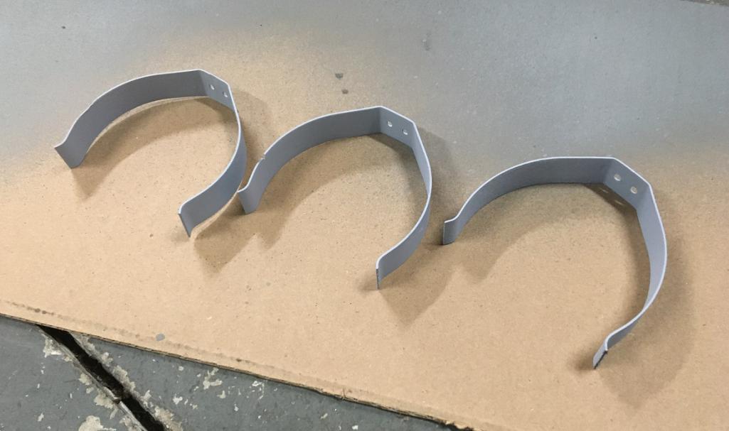 Next, these were riveted using stainless steel rivets. 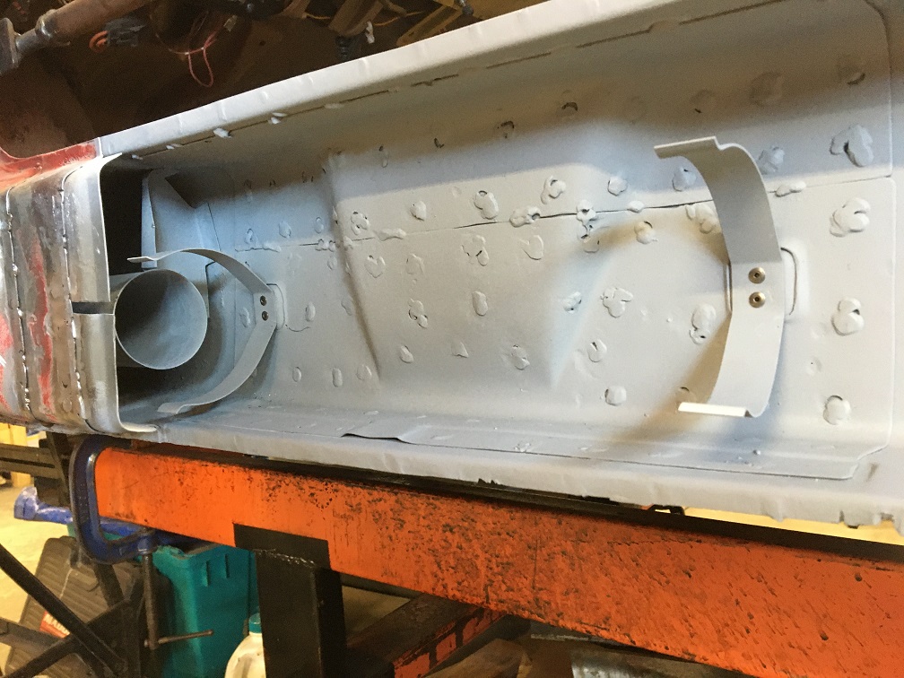 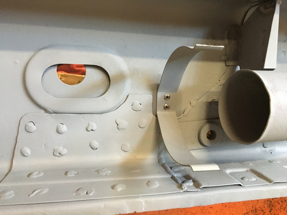 Finally the heater tube was reinstalled. We make all of these efforts to restore our little cars and have once in a while the satisfaction of installing simple parts. The process takes a minute but is very rewarding! (IMG:style_emoticons/default/smile.gif) There you go! 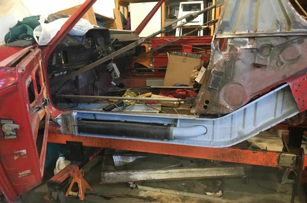 Now let move on to the preparation of the inner rocker. I am actually working on a full length donor piece that includes the rear outer suspension console and those "U" shaped braces that connect the outer console to the inner one. Once this whole piece is ready to go in, it will be another fun milestone. Now, although in good condition, the part needed some attention in the usual area. There was some deep pitting on the lower part of the jack pyramid, so, cut , inspect, cut more, fabricate, weld, grind, rinse repeat... (IMG:style_emoticons/default/smash.gif) (IMG:style_emoticons/default/welder.gif) Part already trimmed and about 95% fitting on the car. 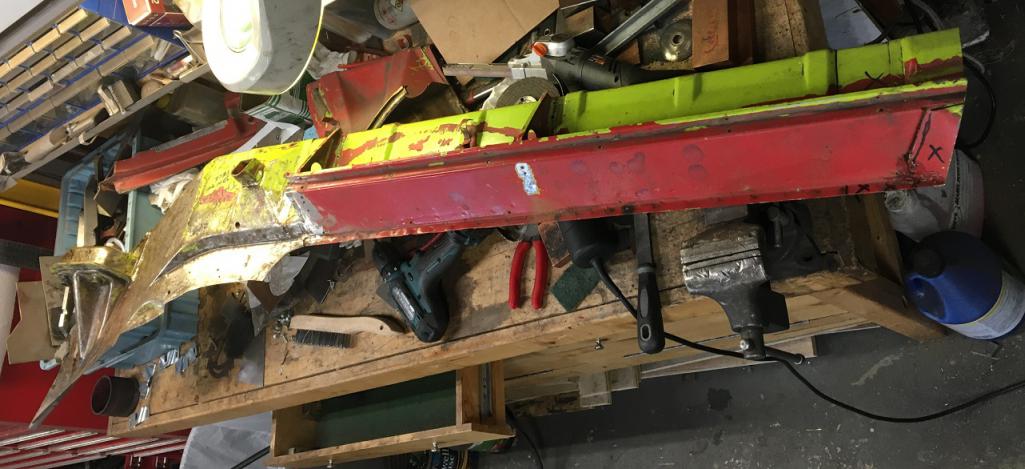 Rusted bottom area of the jack pyramid. 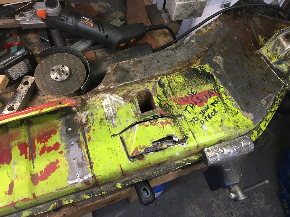 Pyramid partially removed to expose the problematic area. 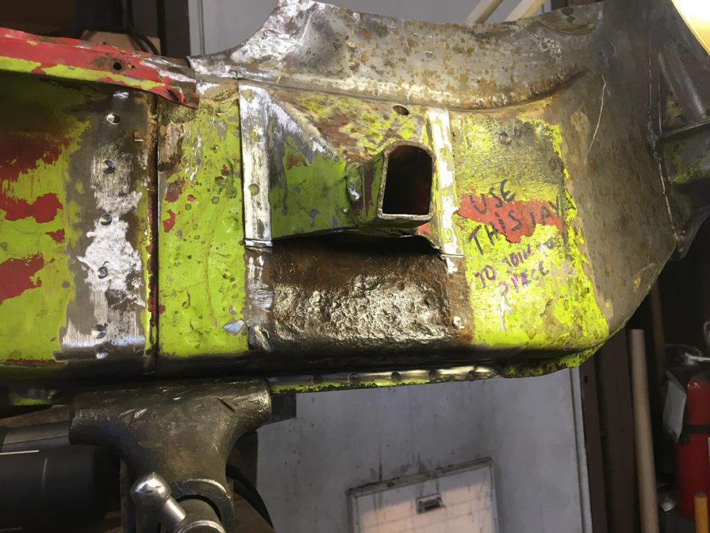 This portion needs to be replaced. The inner rocker is double lareyed in this area. 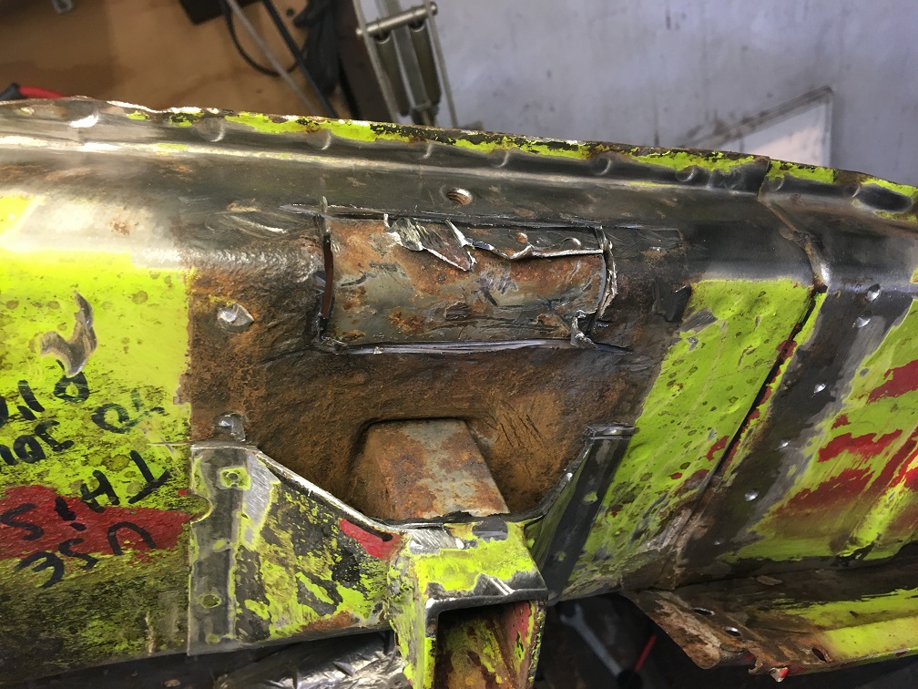 Now the area has been cleaned up and is ready for its patch. 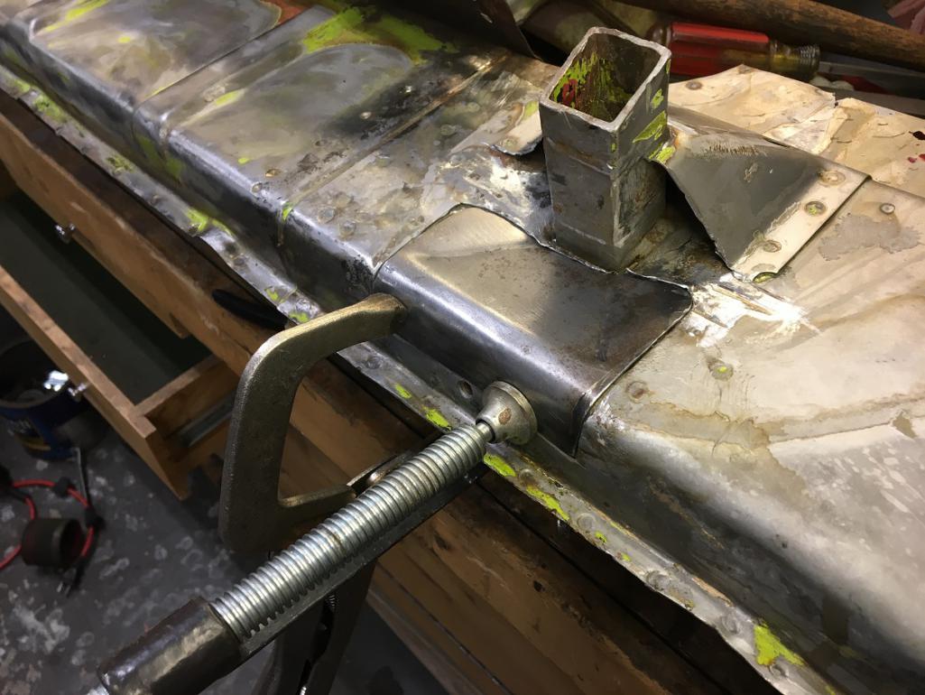 All welded up. 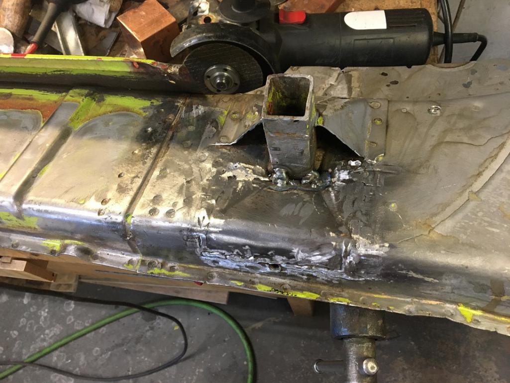 Continuation on the next post... (IMG:style_emoticons/default/smile.gif) |
|
|
|
| Montreal914 |
Oct 18 2025, 10:19 PM
Post
#183
|
|
Advanced Member Group: Members Posts: 2,075 Joined: 8-August 10 From: Claremont, CA Member No.: 12,023 Region Association: Southern California |
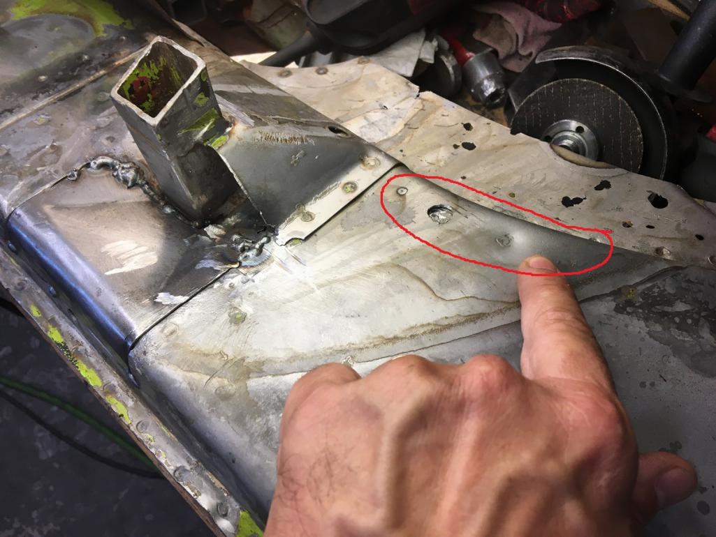
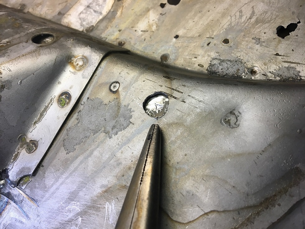
When lookin at double layered area of the structure, I am always concern when seeing bulges like these in between spotwelds. Sometimes these are due to rust in between that expands and pushed outward the second layer. To make sure, I drilled a small window in the outer layer to discover only very nice metal. Relief, we are good to go.
  Next step, close the bottom of the pyramid. While in there I re-sqaured the jack tube that was suffering from the classic stretched upper face. 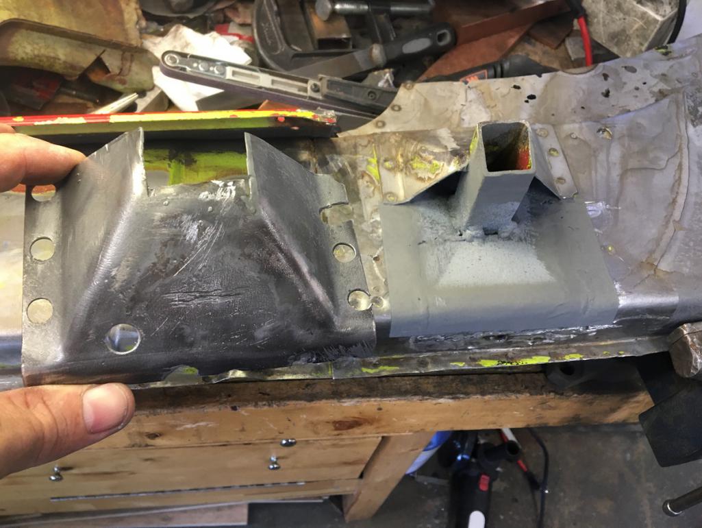 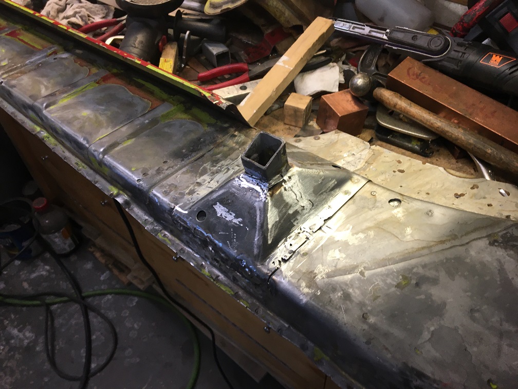 Now to fit the part onto the car. I will spare you the well over 20 times of install, remove, trim, try again, and show you the 98% finish fit. There is hope!! (IMG:style_emoticons/default/smile.gif) 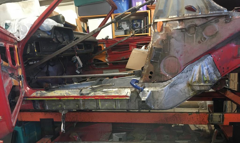 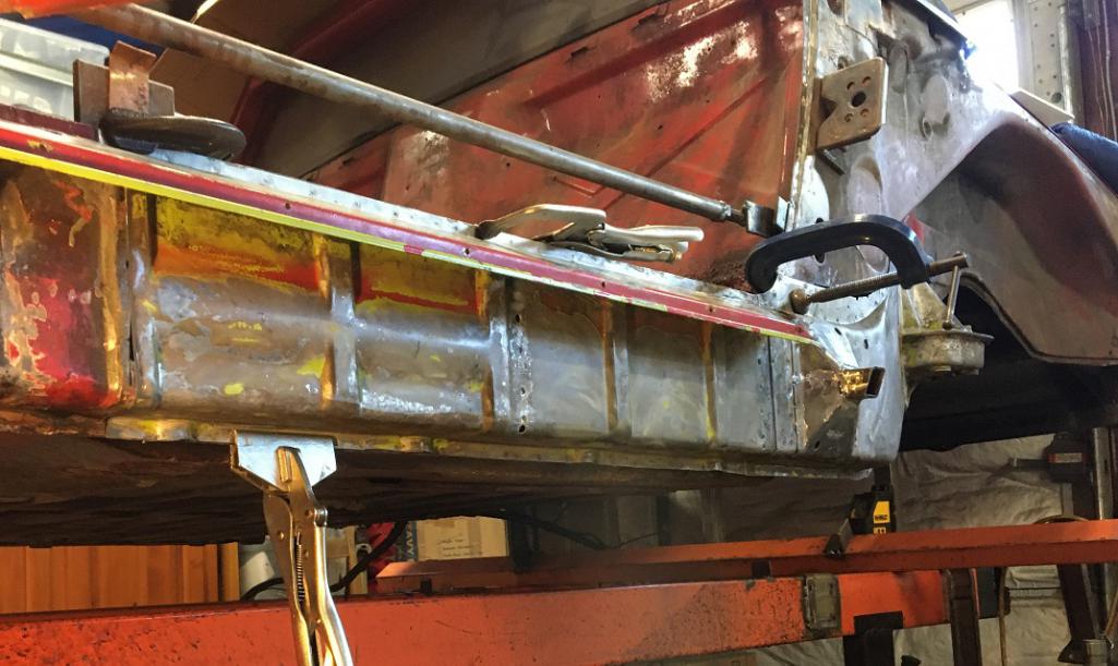 Using my laser I checked the Z (height) location of the bottom of the outer suspension console. I did also compare many reference measurements with the passenger side and things are now lining up whithin 1/16". I am hoping to improve this upon final installation, but this is pretty good at this point. 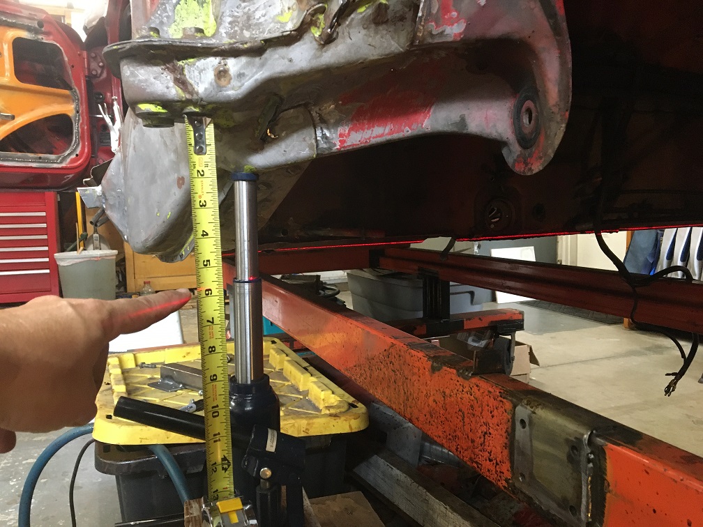 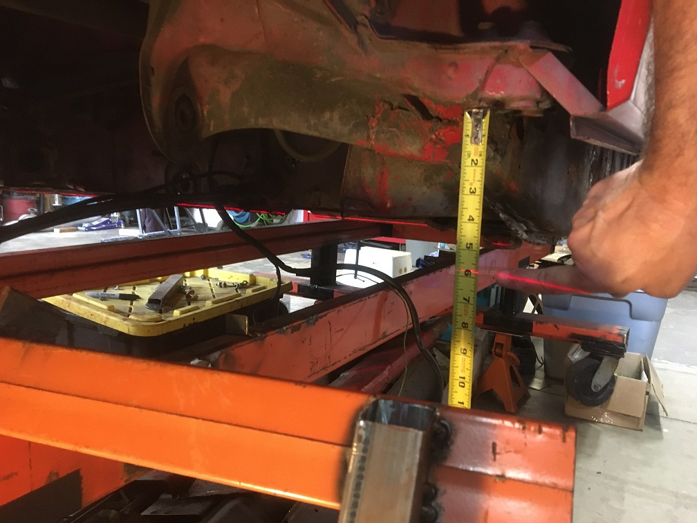 |
|
|
|
| Montreal914 |
Dec 22 2025, 01:10 PM
Post
#184
|
|
Advanced Member Group: Members Posts: 2,075 Joined: 8-August 10 From: Claremont, CA Member No.: 12,023 Region Association: Southern California |
So, last post I showed the progress in the preparation of the outer piece of the longitudinal. Before installing it on the car, I will be stiffening it up with a Restoration Design outer clam shell. It seemed a lot easier to add this layer to the outer long on my workbench.
I bought the RD clam shell from Bruce Stone (IMG:style_emoticons/default/smilie_pokal.gif) and for some reasons the part had been cut in its life. 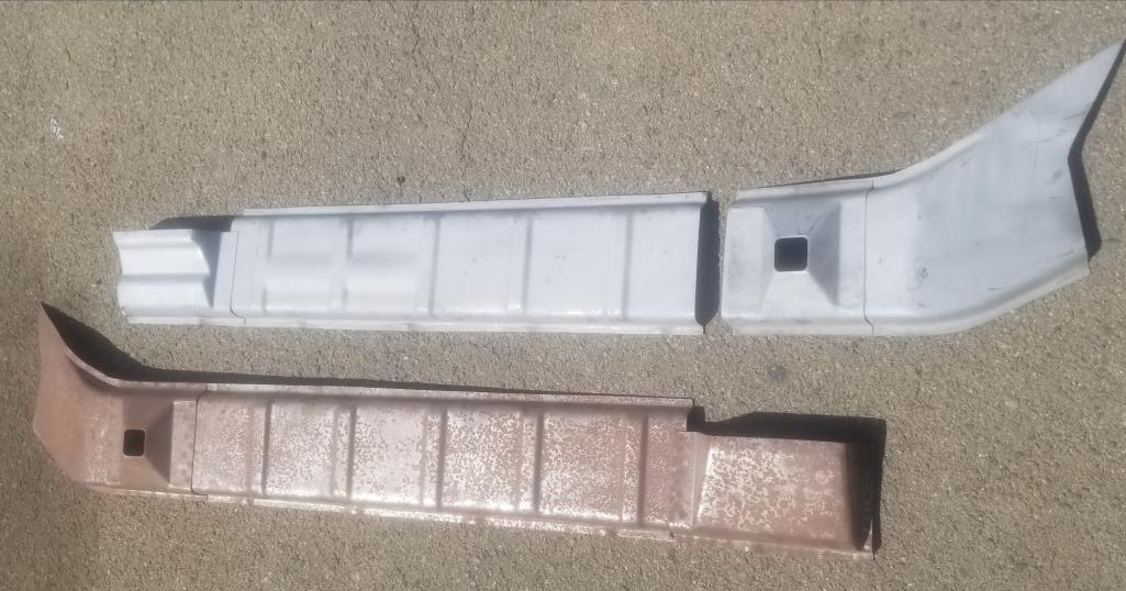 Disclaimer: Some of the following pictures are out of sequence in the build steps as I forgot to take snapshot of every detail, but you will get the idea... First, I debated weather to remove the door sill from the long to install the complete clamshell but I didn't want the sill to be higher up when reinstalled due to the added layer. I also didn't want to have 3 layers of metal at the pinch weld so the door seal could fit properly. By doing this, I did remove some of the clam shell strength but this is already sort of overkill with the car now having the inner strengthtening kit. I figured this would be fine. (IMG:style_emoticons/default/rolleyes.gif) Cut! 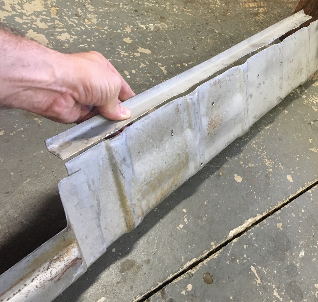 Next, time to test fit this to the side long. I have to give credit to Restoration design here for making a very nice and conforming part. (IMG:style_emoticons/default/sunglasses.gif) The RD part (painted) is on the bottom and the the factory longitudinal piece (bare metal) on the top. We can also see the door sill extending out on the right. 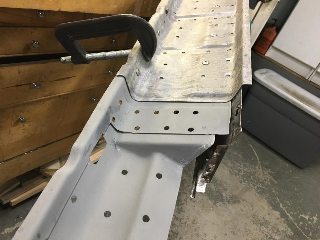 Here we can see the entire RD clam shell on the long. The rear portion was treated with Ospho which gives it a galvanized steel look. Because of that, you can clearly see the two pieces (not yet welded) joint ahead of the jack point pyramid. One detail though, the clam shell pyramid seems a little offset towards the back. (IMG:style_emoticons/default/idea.gif) 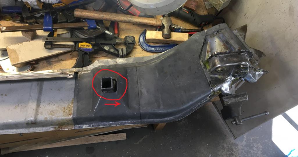 After investigation, it looks like the pyramid was welded a little off. 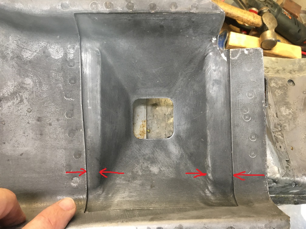 Easy fix. Drilled the spot welds and moved it to properly fit the stock pyramy and jack tube. The required offset is visible from the drilled spot welds here. 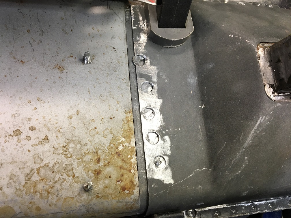 Once this addressed, time to make the clam shell whole again. (IMG:style_emoticons/default/welder.gif) I am using a thick copper flat bar held in the wise as a surface back to do the butt weld of the clamsheel pieces. 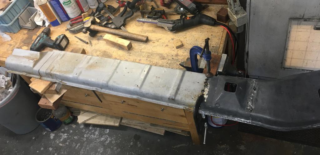 And is the RD clam shell back in one piece. (IMG:style_emoticons/default/smile.gif) 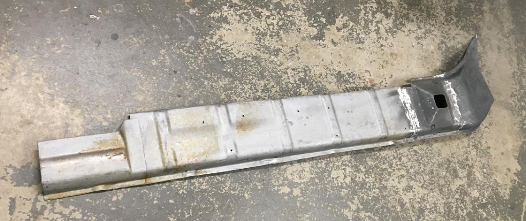 ...And now both the longitudinal piece and the RD piece are ready to be welded together. Plugweld holes have been strategically places for the upcoming steps. 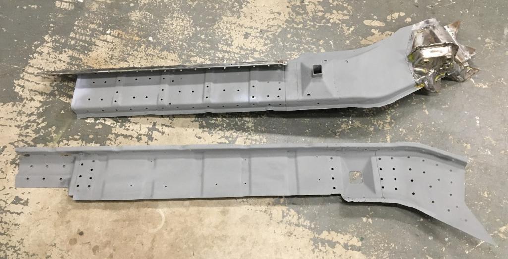 And here is a closeup of the two pieces together prior to welding showing how the RD part (painted) is closely nesting on the stock panel (bare metal) both on the larger area and the recessed vertical webs. Just nice! (IMG:style_emoticons/default/pray.gif) 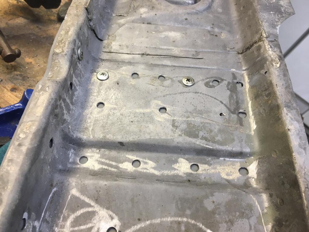 Plug welds from the inside on the door opening stretch. 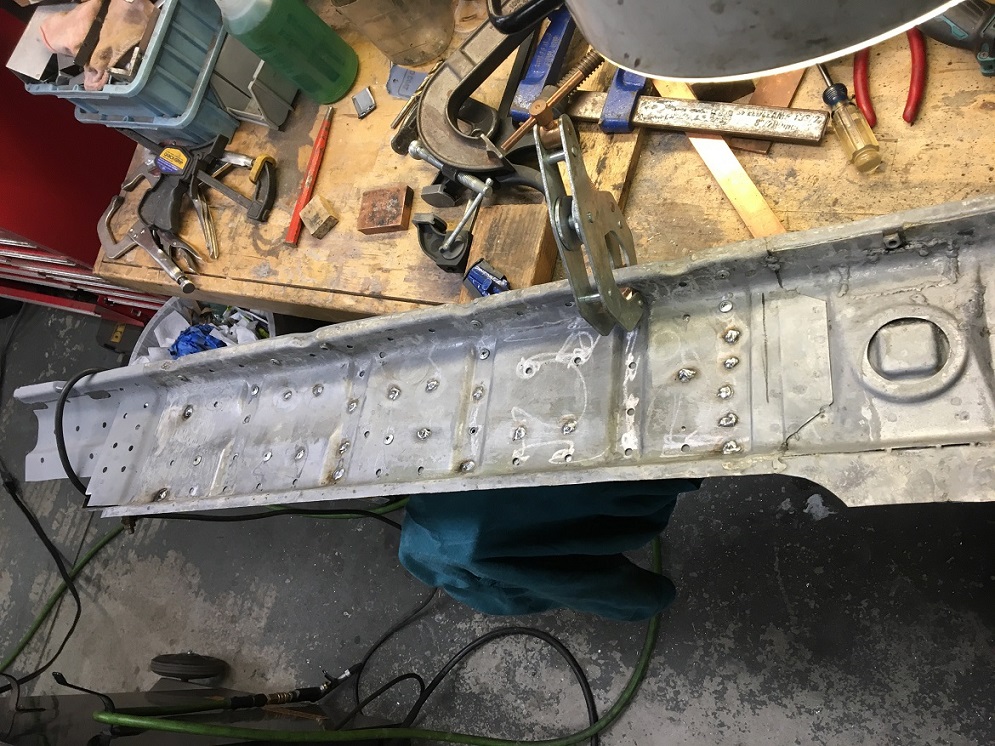 Moving on with the rear elbow portion where the plug welds are done from the outside... 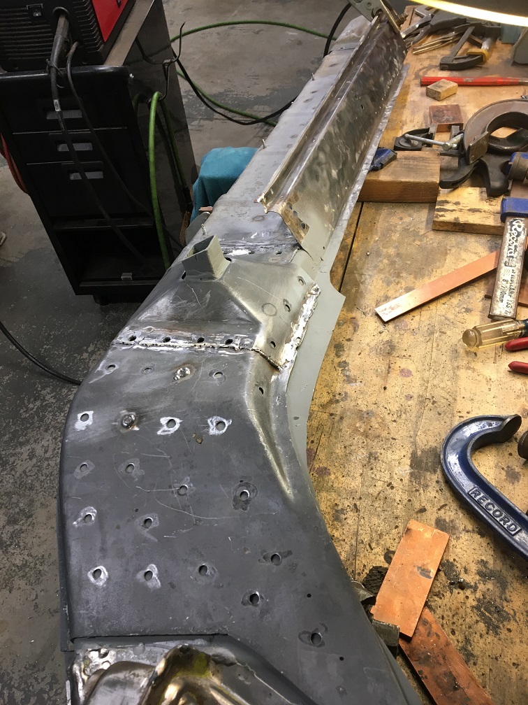 Last one, almost done... 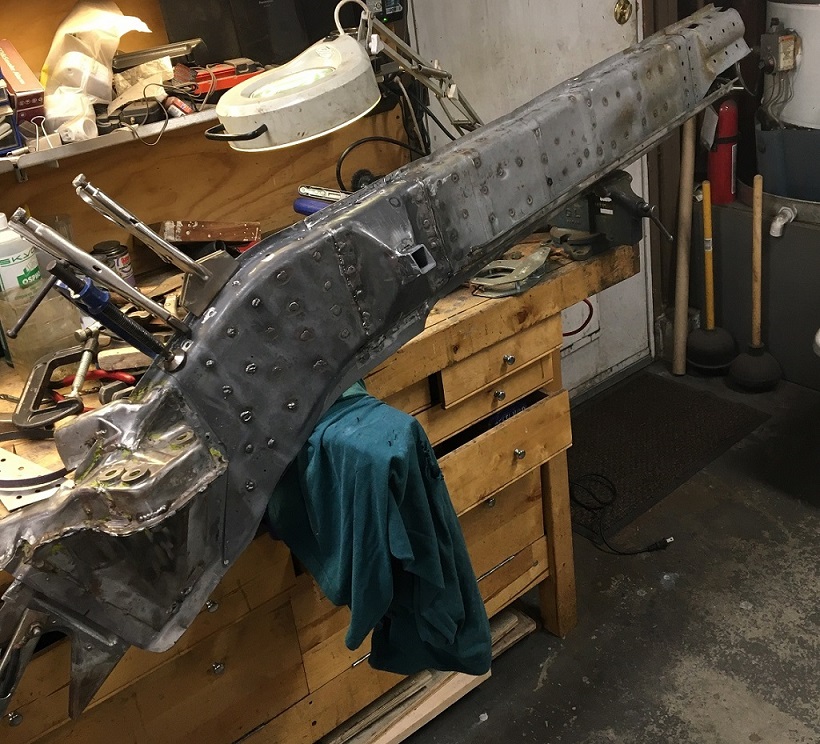 |
|
|
|
| friethmiller |
Dec 22 2025, 01:18 PM
Post
#185
|
|
Senior Member Group: Members Posts: 1,214 Joined: 10-February 19 From: Austin, TX Member No.: 22,863 Region Association: Southwest Region |
(IMG:style_emoticons/default/popcorn[1].gif)
This is one of my favorite build threads! Great work, Eric! This is "pro-level" stuff here! |
 |
|
| Montreal914 |
Dec 22 2025, 01:34 PM
Post
#186
|
|
Advanced Member Group: Members Posts: 2,075 Joined: 8-August 10 From: Claremont, CA Member No.: 12,023 Region Association: Southern California |
(IMG:style_emoticons/default/laugh.gif) And yours is BY FAR my favorite one too! ...where I get my "pro" inspiration. (IMG:style_emoticons/default/smilie_pokal.gif)
I just wish I could be 10% as quick as you are. Looking back at dates, I started the work on the driver's side long in april of 2023 which is 6 months before you started your entire digging from the dead project (IMG:style_emoticons/default/blink.gif) ...and you are at paint now (oh, and work outside too...). Thank you for the boost! (IMG:style_emoticons/default/smile.gif) |
|
|
|
| 930cabman |
Dec 22 2025, 02:45 PM
Post
#187
|
|
Advanced Member Group: Members Posts: 4,576 Joined: 12-November 20 From: Buffalo Member No.: 24,877 Region Association: North East States |
Soo much of this is all about FIT. When everything comes together, life is good. Best to do as you are doing, fit, measure, fit again, measure.
Well done Can you get to a point where you can test fit the doors for a double check? also, second your vote for Fred, his build is far over the top (IMG:style_emoticons/default/aktion035.gif) working outdoors |
|
|
|
| friethmiller |
Dec 22 2025, 08:18 PM
Post
#188
|
|
Senior Member Group: Members Posts: 1,214 Joined: 10-February 19 From: Austin, TX Member No.: 22,863 Region Association: Southwest Region |
QUOTE(Montreal914 @ Dec 22 2025, 01:34 PM)  (IMG:style_emoticons/default/laugh.gif) And yours is BY FAR my favorite one too! ...where I get my "pro" inspiration. (IMG:style_emoticons/default/smilie_pokal.gif) I just wish I could be 10% as quick as you are. Looking back at dates, I started the work on the driver's side long in april of 2023 which is 6 months before you started your entire digging from the dead project (IMG:style_emoticons/default/blink.gif) ...and you are at paint now (oh, and work outside too...). Thank you for the boost! (IMG:style_emoticons/default/smile.gif) QUOTE(930cabman @ Dec 22 2025, 02:45 PM) Soo much of this is all about FIT. When everything comes together, life is good. Best to do as you are doing, fit, measure, fit again, measure. Well done Can you get to a point where you can test fit the doors for a double check? also, second your vote for Fred, his build is far over the top (IMG:style_emoticons/default/aktion035.gif) working outdoors Good thing it’s not a race (IMG:style_emoticons/default/biggrin.gif). It’ll take as long as it takes to get done, as they say. Keep up the great work! |
|
|
|
| Patrick_139 |
Dec 23 2025, 01:42 PM
Post
#189
|
|
Newbie Group: Members Posts: 23 Joined: 2-March 24 From: Claremont Member No.: 27,975 Region Association: Southern California |
You certainly have the do it right once mentality. I can't wait to race around the area with you and your baby
|
|
|
|
| Montreal914 |
Dec 26 2025, 09:54 PM
Post
#190
|
|
Advanced Member Group: Members Posts: 2,075 Joined: 8-August 10 From: Claremont, CA Member No.: 12,023 Region Association: Southern California |
More update. Now, this may look like I am cranking out the work, but this work was done a few short weeks ago... Still, it is motivating and there is definitely more coming up too! (IMG:style_emoticons/default/smile.gif)
Taking advantage of having the outer half of the long on my bench, I continued with stiffening the structure. I forget if I have mentioned it, but I am going "full on" with the reinforcement. This is a narrow body car, but with the 3.2 in it, I prefer to apply the belt and suspender principle. The car will have the inner kit (cabin 3 pieces), the outer clam shell as you have seen in the previous post, and the GT kit on the back end of the chassis. Doing this once. (IMG:style_emoticons/default/wacko.gif) One piece of the GT kit that can be installed on the bench is the small triangle on the outer suspension console. First, shape it so it fits properly. In this picture we can also see the V shaped inner layer of the outer panel. This will get plug welded and used as an overlapping joint when I install the side panel back. 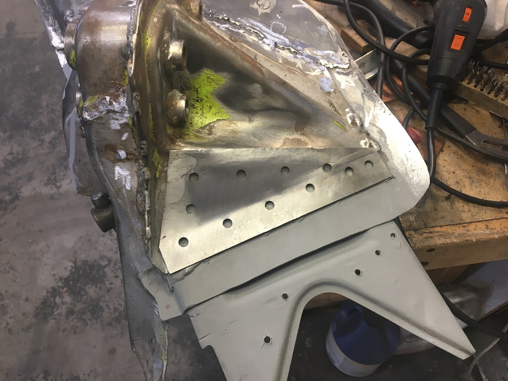 Now prepped with weld through primer on both mating surfaces. 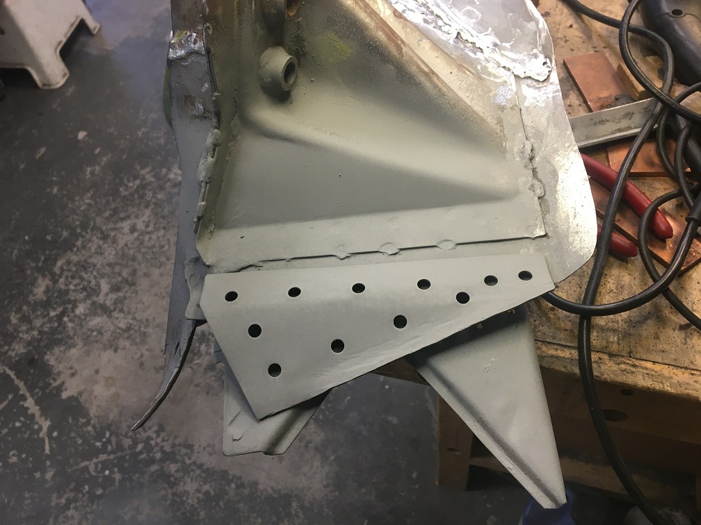 Before doing the plug welds I remove the weld through primer in the hole to avoid splashing. This is actually a Dremel bit in my drill. Works well. 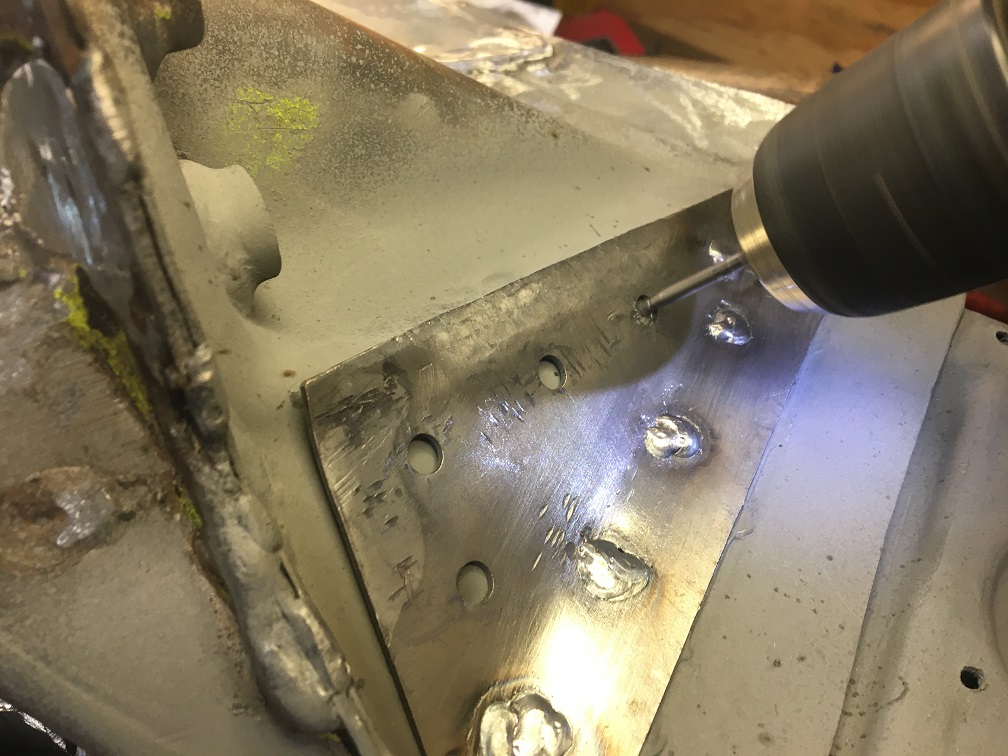 Now plug and edge welded. You can notice that the rear edge is not welded. I am hoping to have the wheel arch piece of the GT kit welded to that edge. 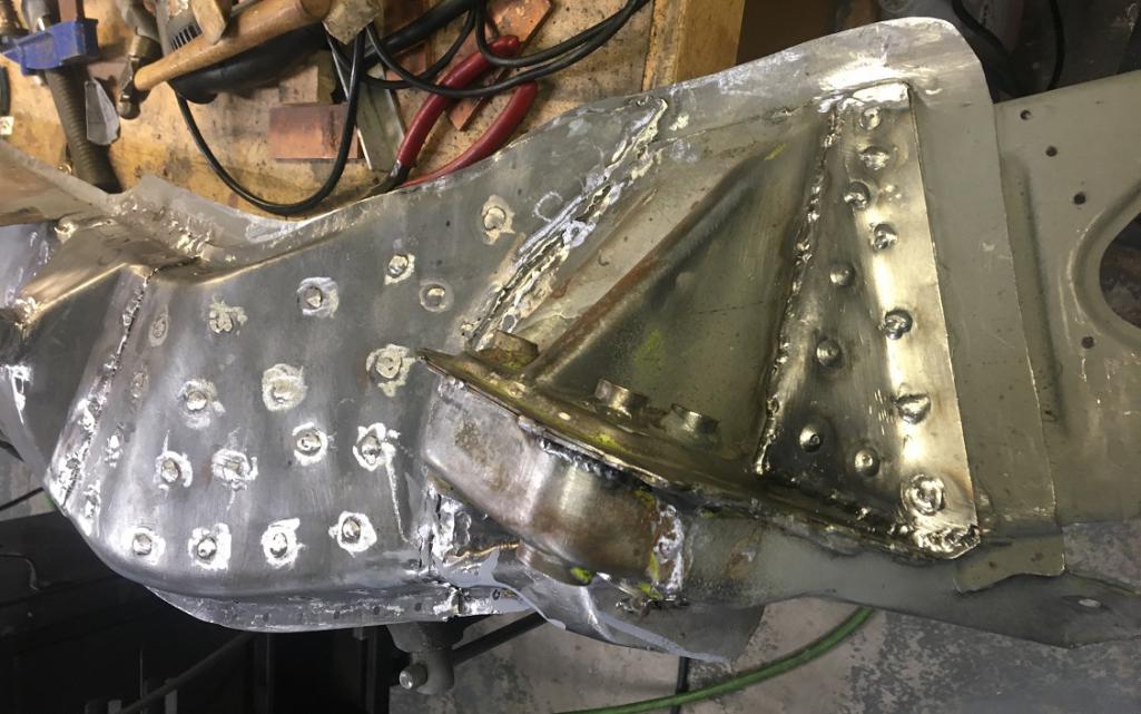 Almost forgetting the sill supports... (IMG:style_emoticons/default/rolleyes.gif) Those were removed to install the clamshell but are going back on now. Because the clamshell adds a thickness of metal, these are no longer fitting. 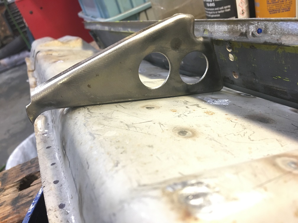 I elected to redo the bend that mounts to the side of the long since this is where the newly added metal is, which made sense to me. Using my trusted 3 1/2" vise, I hammered the 90 degree bend off by the same thickness as the clamshell. 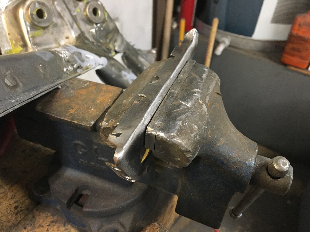 Now, these fit nicely under the sill with all faces in contact. (IMG:style_emoticons/default/sunglasses.gif) 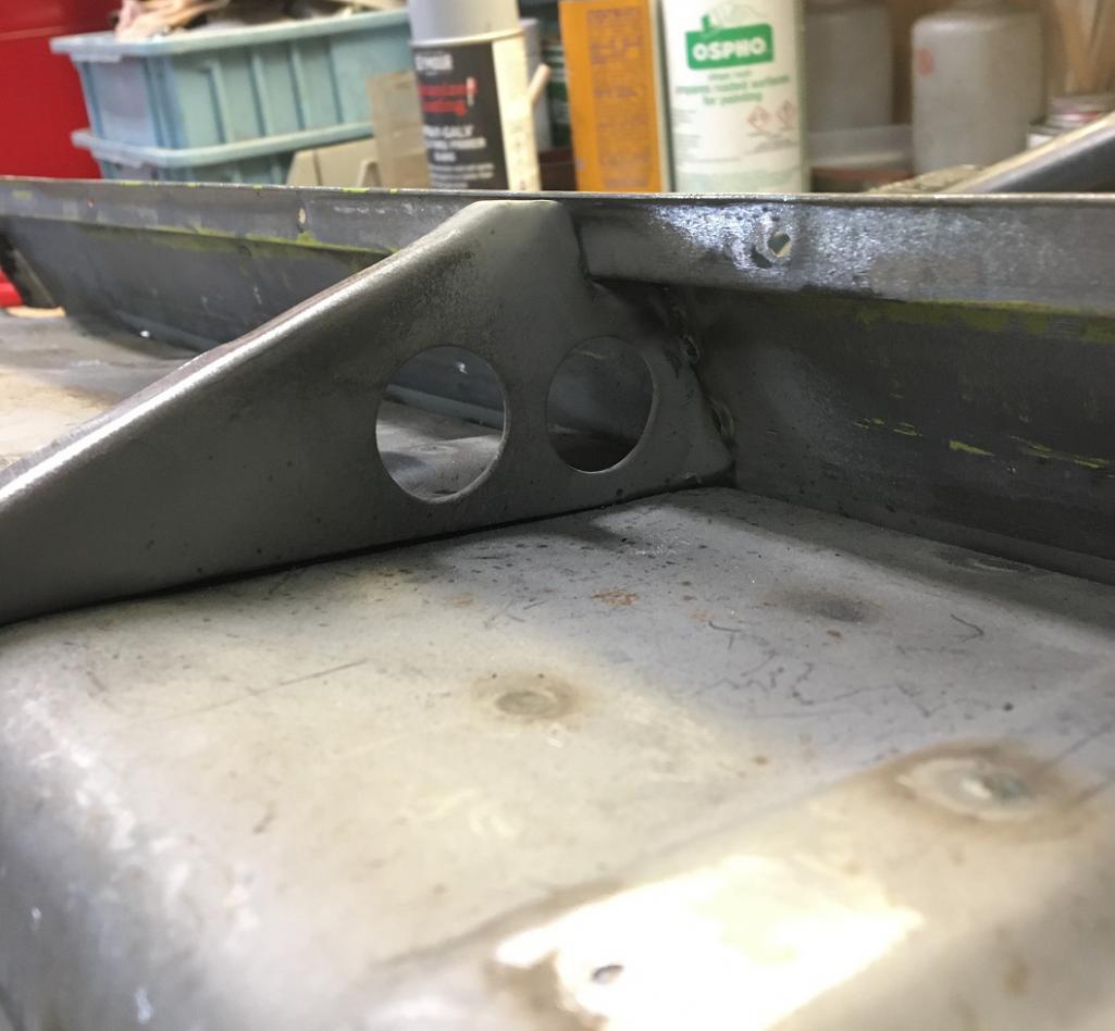 And now all welded up. 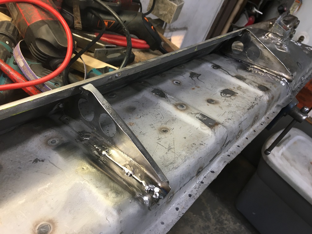 At this point there really isn't anything else I can do with the piece on my bench other than drilling the edges to do the plug welds on the chassis. There are holes drilled in the front to plug weld to the backing that was set earlier on the chassis. More on this later... 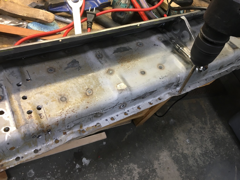 Next, the last series of final adjustments which seems to never end (install check, remove, adjust, reinstall, ...). Part of it simply lies in the fact that this is the very last chance to adjust anything because the next setp is welding. Kind of scary situation, that adds up to my obsession of proper fit... Final laser check of the cylindrical boss on the new piece compared with the passenger side's. This seems pretty good to me. (IMG:style_emoticons/default/sunglasses.gif) 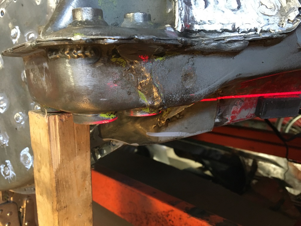 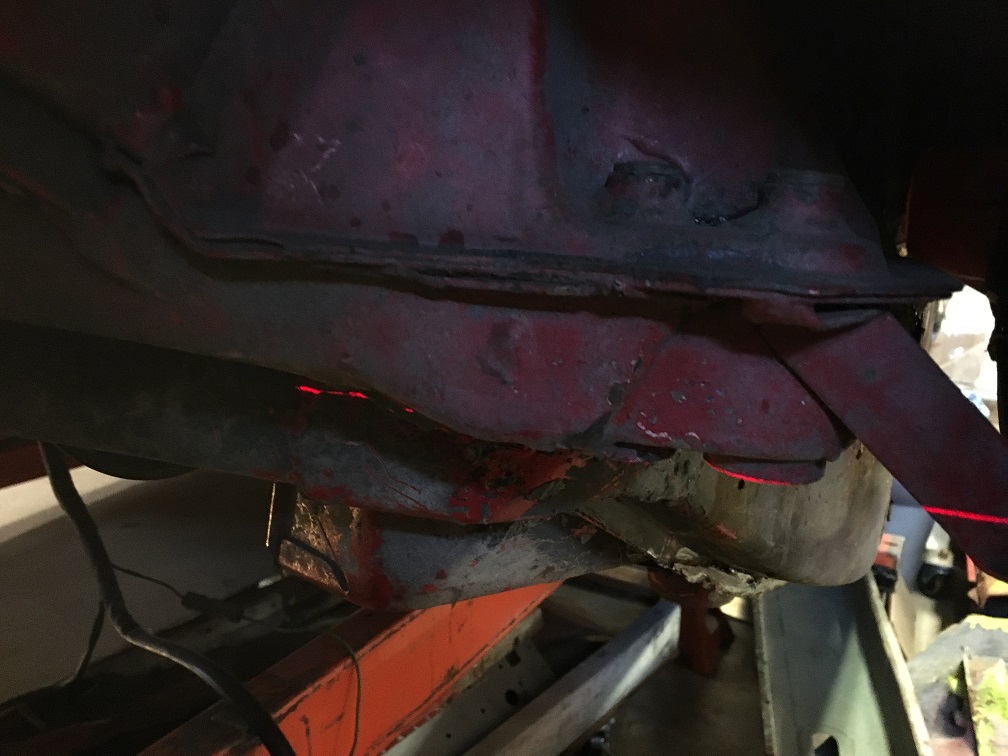 And here is the piece ready for welding in its final mounting. The butt joint gap to the chassis is not perfect, but very manageable to be welded with a gap ranging between 0 and ~1/16". The largest gap is at the tail end vertical (angled) joint, but as you remember, there is that V shaped doubling layer there which will give a good backing for that weld. 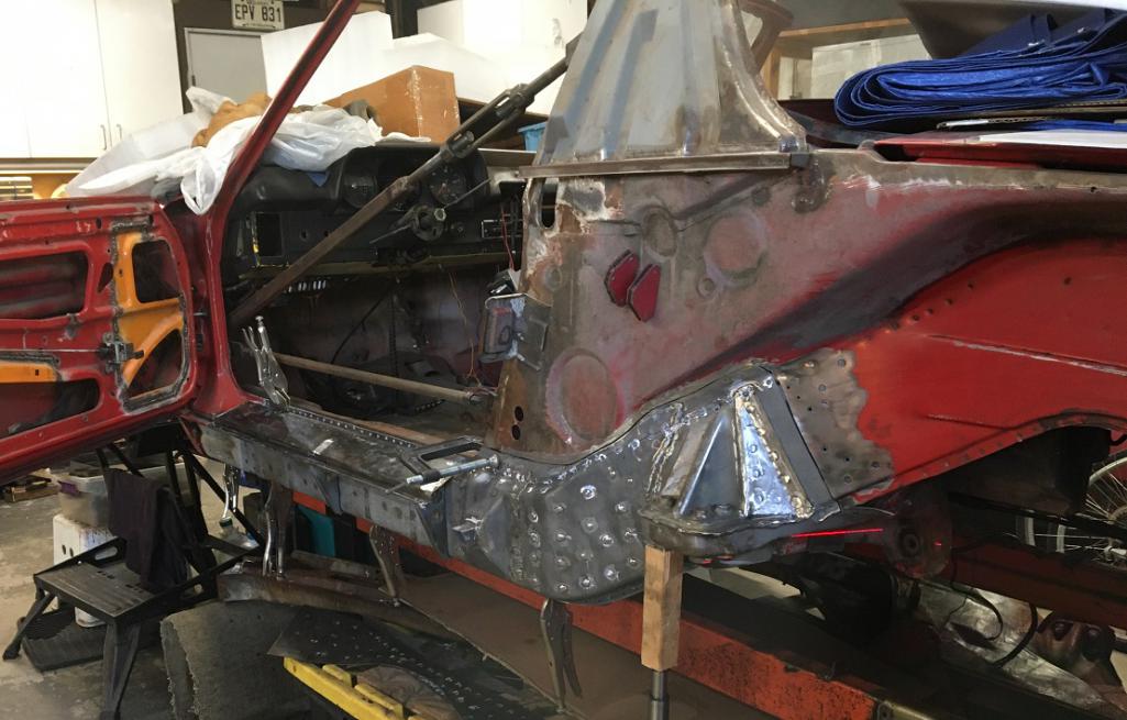 Another angle where you can appreciate the close fit of the Restoration Design clamshell to the door post lower wedge box. 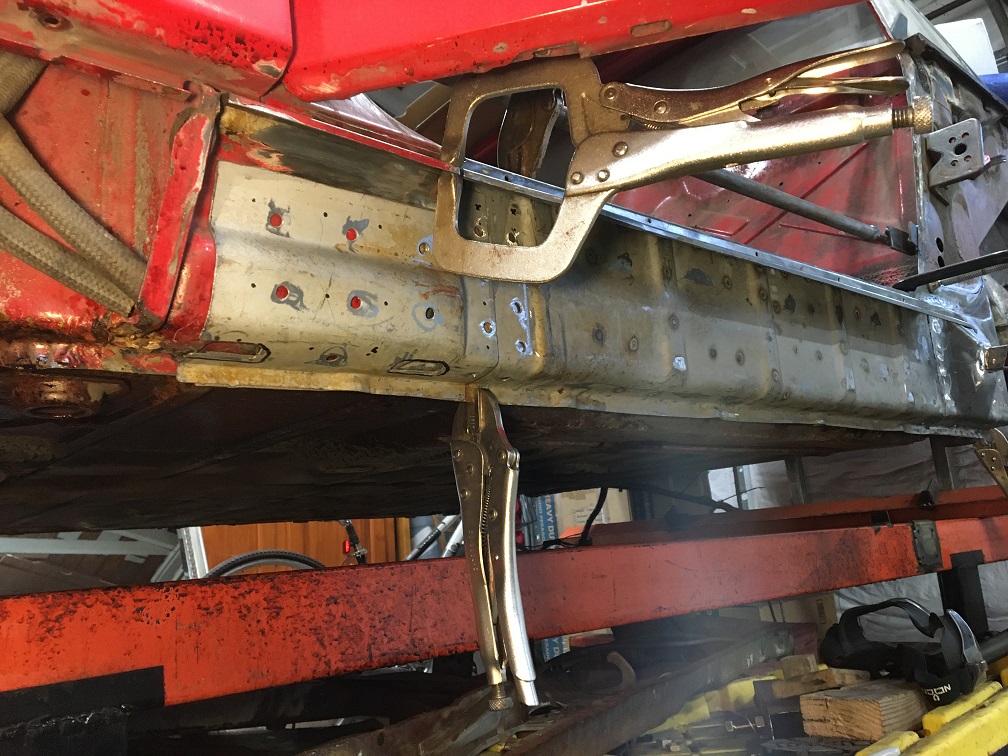 Going back to how the front joint works, In this picture, the red dashed line is the butt joint between the chassis and the inner rocker which happens behind the RD clamshell we are seeing. Just to be sure, I previously added another backing since there will be no access to weld that butt joint seam, only plug welds. 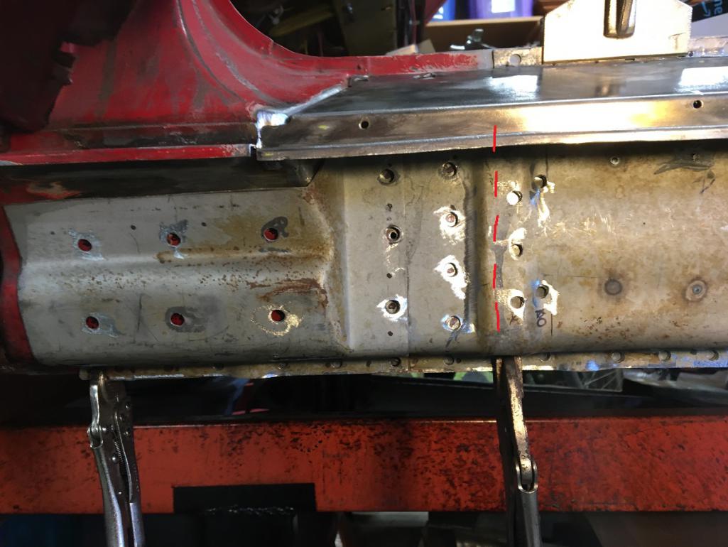 And here is the recall picture of that backing which was installed in post #178. Again the dashed line shows where the butt joint will happen. Obviously the welds we see here were later dressed flush so all the metal could fit nicely. Another note is that the plug welds that will be done upon the installation of the side panel will reach all three layers here (the added backing, the chassis piece and repair inner rocker, and outer clamshell). This should be strong enough with the vertical series of plug welds on both sides of the butt joint. 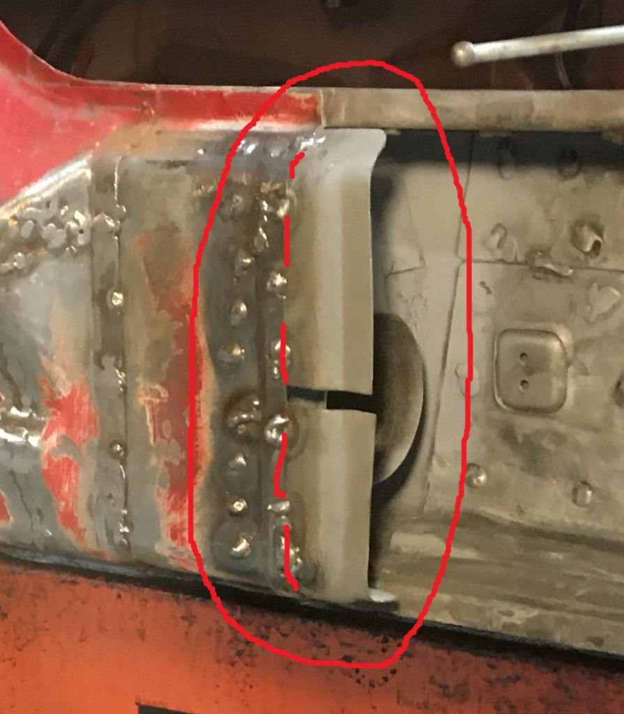 I will continue in another post as I am out of room for more pictures... The story ends well! (IMG:style_emoticons/default/smile.gif) |
|
|
|
| 930cabman |
Dec 27 2025, 07:29 AM
Post
#191
|
|
Advanced Member Group: Members Posts: 4,576 Joined: 12-November 20 From: Buffalo Member No.: 24,877 Region Association: North East States |
we are a crazy bunch for sure
great progress, how is the passenger's side? |
|
|
|
| Montreal914 |
Dec 27 2025, 10:15 AM
Post
#192
|
|
Advanced Member Group: Members Posts: 2,075 Joined: 8-August 10 From: Claremont, CA Member No.: 12,023 Region Association: Southern California |
QUOTE(930cabman @ Dec 27 2025, 05:29 AM) we are a crazy bunch for sure great progress, how is the passenger's side? Definitely crazy. (IMG:style_emoticons/default/screwy.gif) Had I 'd known, I am not sure I would have restored it but there are sentimental values here. This is my first rodeo so I started with the driver's side to learn... knowing the passenger side will be worse... (IMG:style_emoticons/default/rolleyes.gif) The good news is I now feel ready to tackle it! (IMG:style_emoticons/default/sunglasses.gif) First, l will share the completion of this side and also temporarily fasten the fender to check the fit with the door as you suggested. (IMG:style_emoticons/default/thumb3d.gif) Fingers crossed. |
|
|
|
| Montreal914 |
Dec 27 2025, 12:52 PM
Post
#193
|
|
Advanced Member Group: Members Posts: 2,075 Joined: 8-August 10 From: Claremont, CA Member No.: 12,023 Region Association: Southern California |
More update! (IMG:style_emoticons/default/smash.gif) (IMG:style_emoticons/default/welder.gif)
And so the welding process begins on this large piece. One little spot at a time. First I checked one last time the targa top distance between the top corner of the windshield frame and the top corner of the Targa roll bar. 25 1/8", all is good. Here is a view of the rear area where two series of welds need to happen on the top. The first one is joining the outer panel assembly to the inner longitudinal flange which is done via plug welds in the line of holes. At the bottom of these holes, we can see the folded flange with weld through primer. Note that because this outer panel is now layered with the RD clamshell, these plug welds will join all three layers at once. The second weld is a long butt weld to join the repair piece to the inner fender cut that goes all the way to the door's rear opening in the chassis. 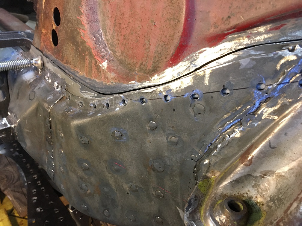 Here is the back side viewed from the engine bay. Again, the longitudinal flange on the bottom and the obvious (color difference) butt joint line on the top. 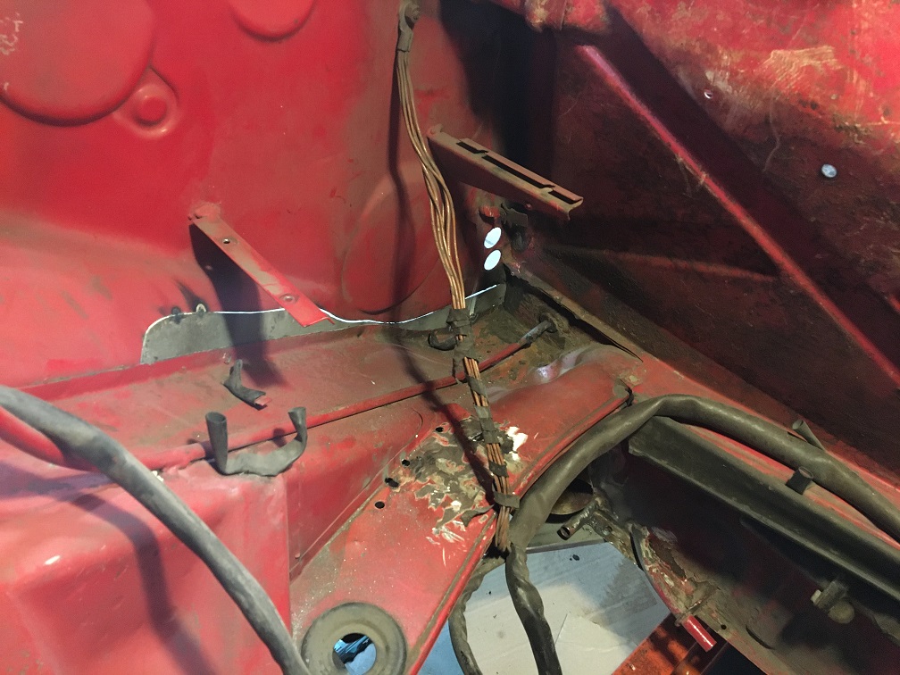 The part is now held by a few tacks. You can see how I used that factory "V" double layer to create a lap joint (yellow dashed line) using self tapping screws to bring it against the back side of the chassis (in red). We can clearly see the V shaped layer still primered at the bottom of the holes. Although cleaning those holes with the drill as previously shown could be done a lot faster if done all at once. I ususally clean only one at a time which helps me remember whick hole I was going to plug next, and gives a little more time in between the welds too. I do cool down each weld with compressed air. Needless to say, this is a long and slow process... (IMG:style_emoticons/default/laugh.gif) 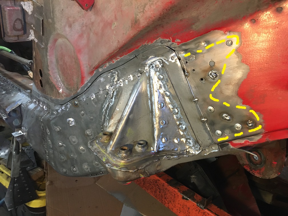 The joining of both flanges on the door opening section is nice and to make sure is stays that way, I set a couple of vise grips on either side of each plug weld which gives a good result as you can see in these next pictures. Spot welder would be great here but I don't have any 220V in my garage so... (IMG:style_emoticons/default/dry.gif) 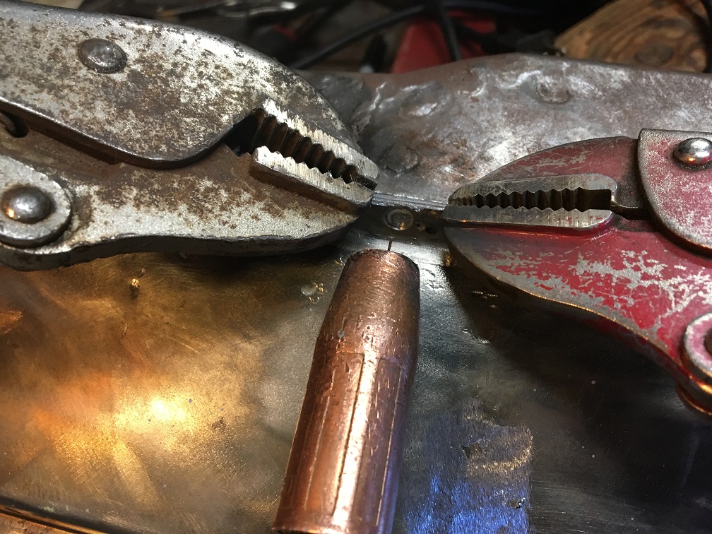 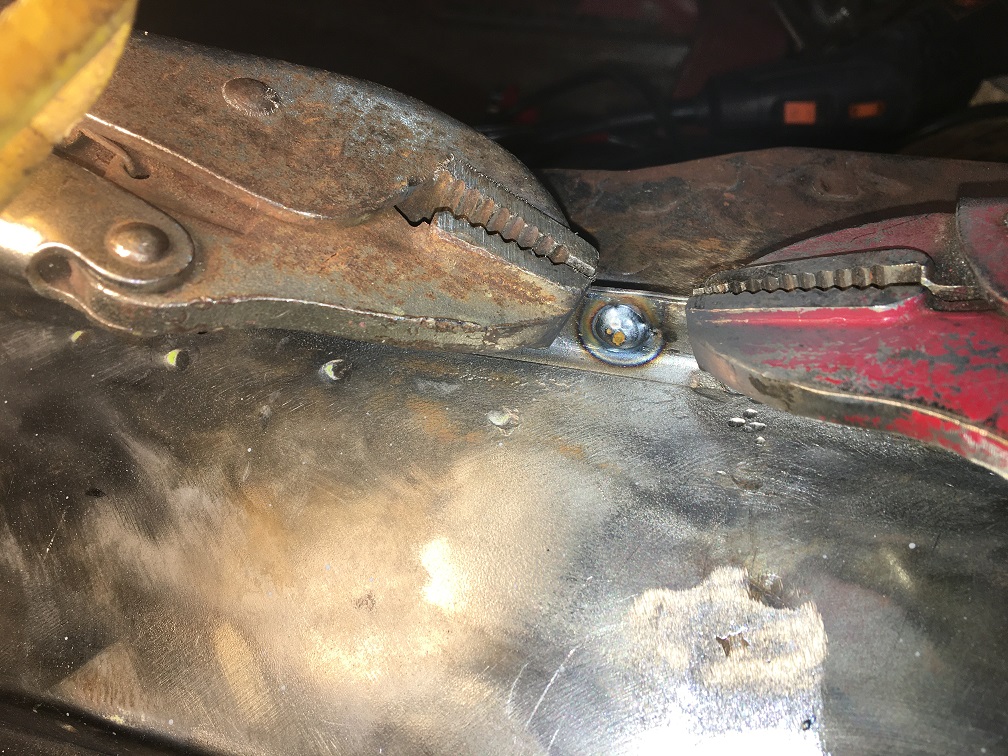 Slow progress, one spot at a time. Notice the red laser still shining on that lower edge of the suspension cylindrical boss. 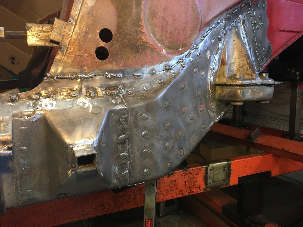 For the rocker panel ledge joint, I used a 1/2" aluminum extrusion I had and held it underneath it with vise grips and clamp to ensure the colinearity of the repair panel portion and the existaing chassis bit in the front. 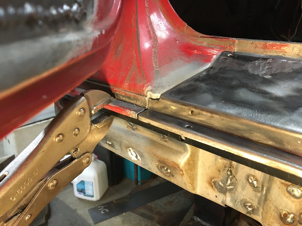 After over two days of slow welding, I was reaching the end. One of the last step was welding the ties from the outer suspension console to the inner console. As part of my donor piece, I had gone through great care in keeping the ties with their factory welds to the outer console. I figured these ties would be another good reference point when joining to the chassis and inner existing console. In the picture below, circled in red are the factory untouched welds and in blue is the area where I will be welding to join the existing inner console. 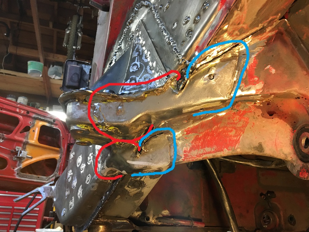 And here is the end result all welded up! (IMG:style_emoticons/default/beer3.gif) You can see I am already mocking up the next step which is the GT stiffening kit in the wheel arch area. 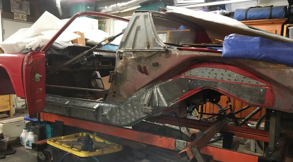 Again, to make sure the junction of the repair panel to the chassis is strong, The front part of the GT panel is overlapping the butt joint and you can see by the sharpie dots where I will drill extra holes to have a series of plug welds on either side of the underneath joint. 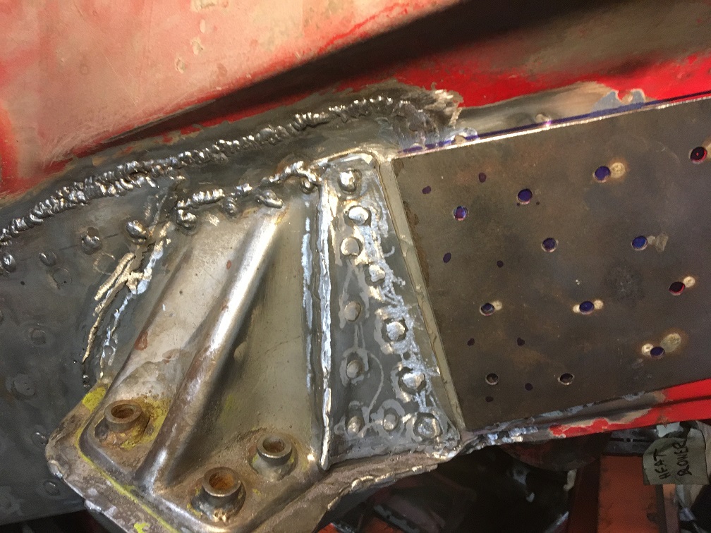 Chassis with removed paint in the wedling areas. Weld though primer was applied to the surface as usual (not shown). 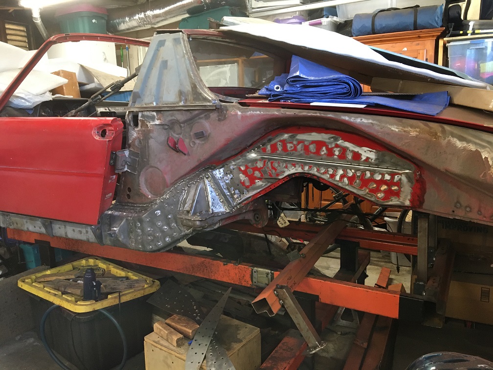 Installation begins with the top piece. 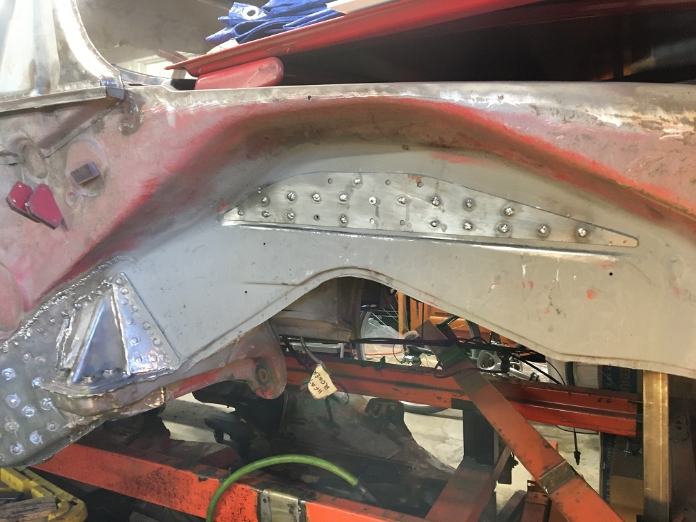 The marks on the edges is me making sure the piece is really againts to body. 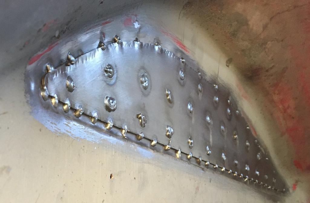 And here is the final results with both GT pieces installed. (IMG:style_emoticons/default/smile.gif) 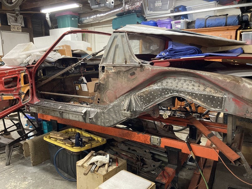 |
|
|
|
| friethmiller |
Dec 27 2025, 01:12 PM
Post
#194
|
|
Senior Member Group: Members Posts: 1,214 Joined: 10-February 19 From: Austin, TX Member No.: 22,863 Region Association: Southwest Region |
Yes!! Nice work! (IMG:style_emoticons/default/welder.gif)
|
|
|
|
| Cairo94507 |
Dec 28 2025, 09:21 AM
Post
#195
|
|
Michael Group: Members Posts: 10,610 Joined: 1-November 08 From: Auburn, CA Member No.: 9,712 Region Association: Northern California |
I really enjoy seeing the structure of our cars as they are repaired; very nice work. (IMG:style_emoticons/default/smilie_pokal.gif)
|
|
|
|
| _stickykitty79_ |
Dec 28 2025, 11:32 AM
Post
#196
|
|
Newbie Group: Members Posts: 33 Joined: 20-August 24 From: socal Member No.: 28,302 Region Association: None |
this falls under the r/oddlysatisfying thread in Reddit for sure. im a couple months away from doing allll this same stuff. laser level is a good idea if consoles are removed
|
|
|
|
| Montreal914 |
Dec 28 2025, 12:22 PM
Post
#197
|
|
Advanced Member Group: Members Posts: 2,075 Joined: 8-August 10 From: Claremont, CA Member No.: 12,023 Region Association: Southern California |
Final update of the year which shows the current state of the project.
All of the welds on the driver's side have now been ground smooth. I also put back both legs on the orange jig that support the chassis on the inner rear suspension consoles. For a while now, the chassis was only being supported by the front suspension rear anchor point and the gearbox rear mounting location which is quite a span for the chassis to flex during welding. I was very please when I reinstalled the two legs that everything went on and holes lined up. Another sign the chassis had not moved. 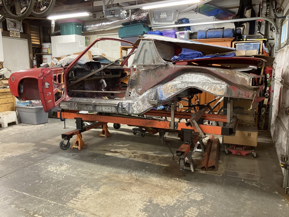 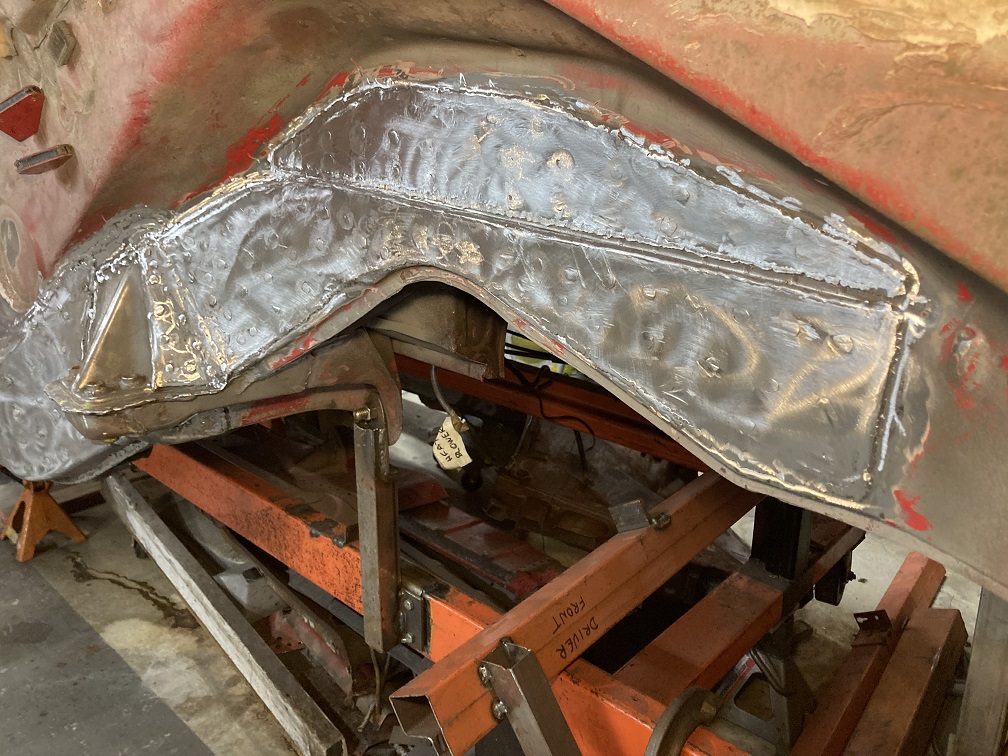 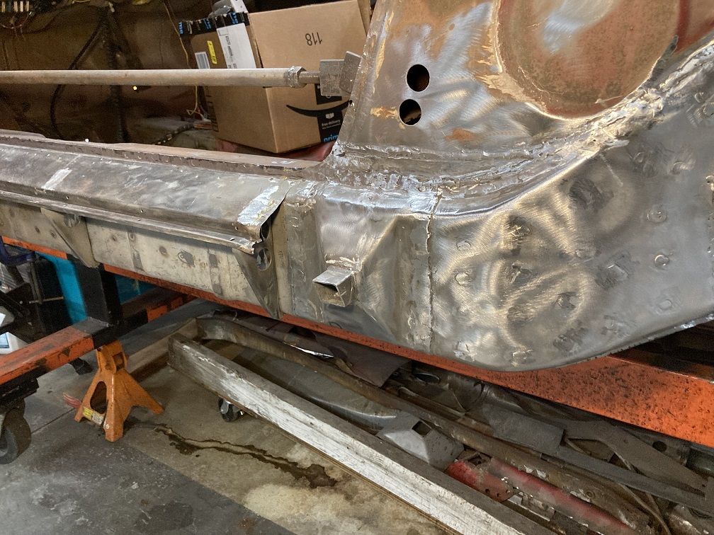 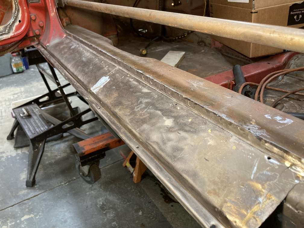 While looking at the passenger side, the pinch weld on top of the long in the door opening caught my attention. Left is the passenger side with the factory spot welds and right is the driver side with the new welds. It was a feel good moment. (IMG:style_emoticons/default/biggrin.gif) 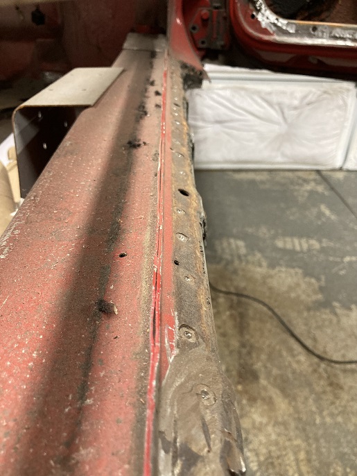 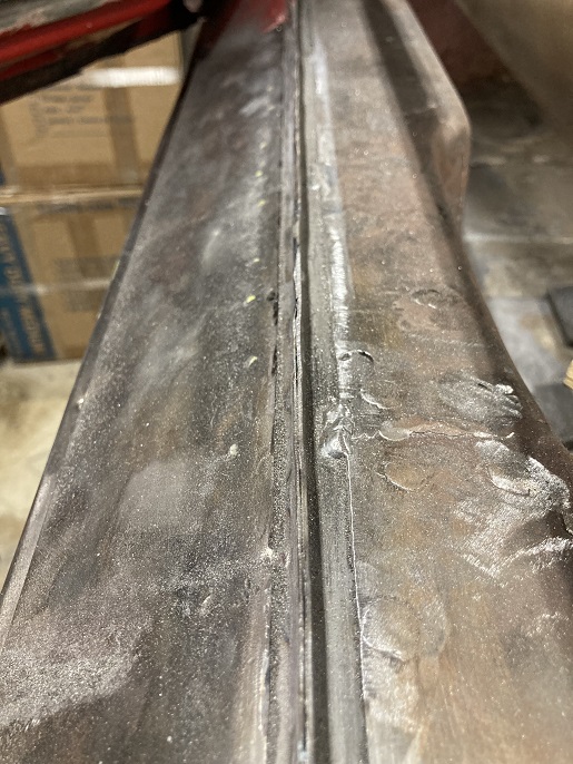 Next, I followed @930cabman recommendation and put the rear fender on to see if things had shifted in this whole process. The fender is only held by a couple of vise grips here but the fit is promising. The rear door gap is a little large but seems to be similar to the gap I had in post #98 about 2 years ago... Post #98: http://www.914world.com/bbs2/index.php?s=&...t&p=3060756 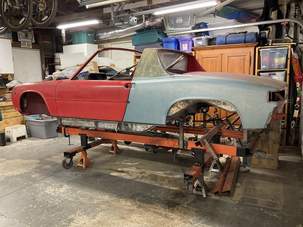 This concludes the restoration and reinforcement work on the driver's side longitudinal beam. (IMG:style_emoticons/default/beer3.gif) Time to take the car for a spin! (IMG:style_emoticons/default/w00t.gif) (IMG:style_emoticons/default/driving.gif) 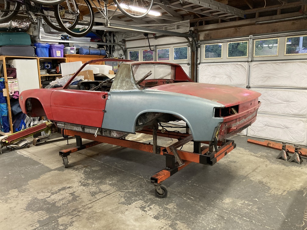 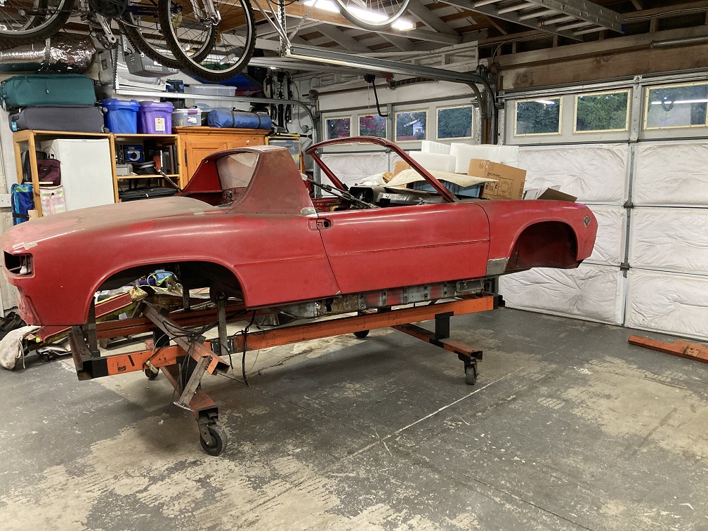 ...short drive to the new work configuration. I then set the orange jig back on jackstands (IMG:style_emoticons/default/rolleyes.gif) making sure both the jig and car are laser leveled, which provided some appreciation of chassis straightness. Note the laser line at the bottom of the rear apron. 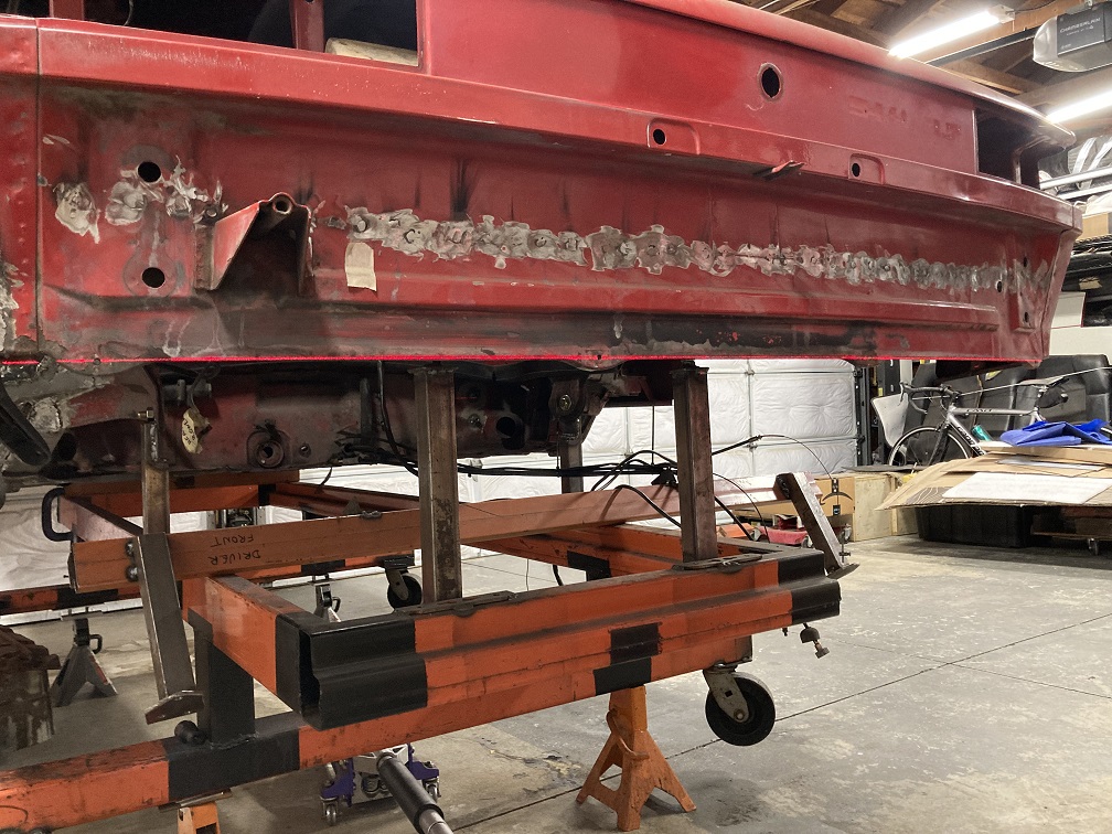 Then I lowered the laser to the height of the cabin floor rear seam weld at the firewall. I am pinching that weld on both sides in the following couple of pictures. 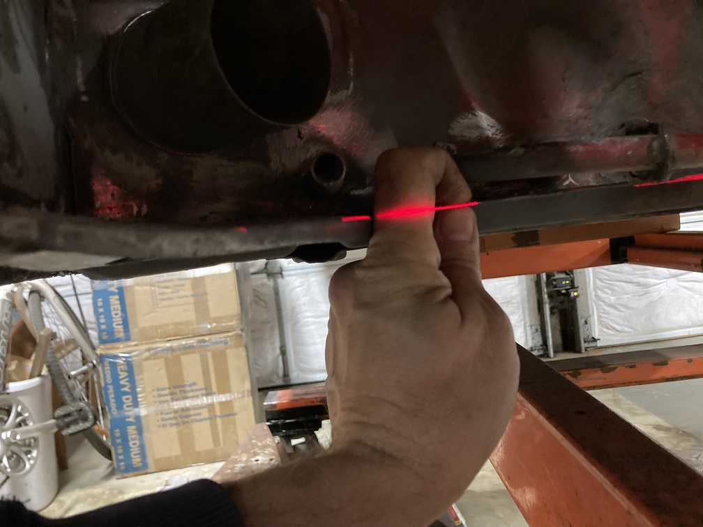 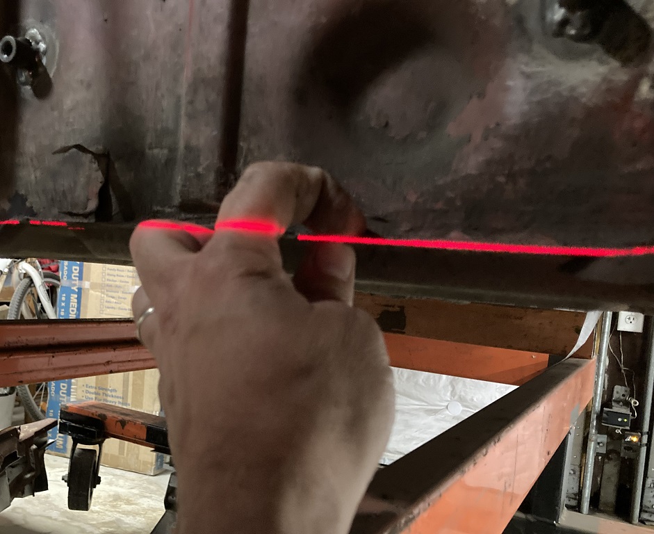 And one last check point, rear outer suspension console cylindrical bosse on each side. (IMG:style_emoticons/default/smile.gif) 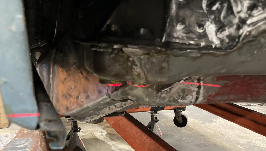 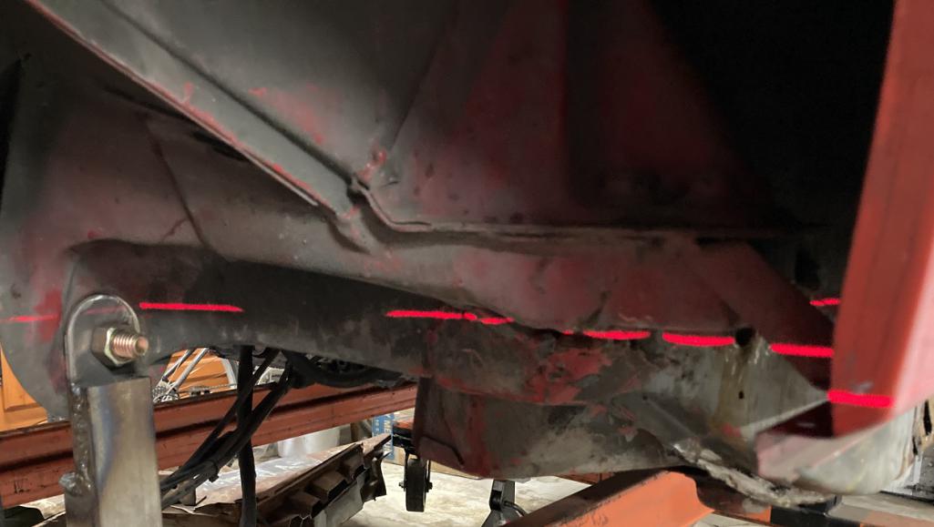 The chassis is now set for the passenger side longitudinal restoration. I obviously expect worse conditions from the nature of our cars with its battery location. There are also some prior repairs that were done by previous owner(s) and some patching done by me that I will be revisiting. I invite you to follow the progress in the coming weeks, until then wishing everyone a happy new year! (IMG:style_emoticons/default/cheer.gif) |
|
|
|
| 930cabman |
Dec 28 2025, 01:47 PM
Post
#198
|
|
Advanced Member Group: Members Posts: 4,576 Joined: 12-November 20 From: Buffalo Member No.: 24,877 Region Association: North East States |
Love watching this, just wishin my ageing bones could ever think about keeping up with you or Fred
Thanks for posting this all good stuff, many folks will refer to these builds as they go down the long road |
|
|
|
| seanpaulmc |
Dec 28 2025, 05:51 PM
Post
#199
|
|
Member Group: Members Posts: 439 Joined: 6-December 16 From: Orlando, FL Member No.: 20,649 Region Association: South East States |
|
|
|
|
| friethmiller |
Jan 1 2026, 01:05 AM
Post
#200
|
|
Senior Member Group: Members Posts: 1,214 Joined: 10-February 19 From: Austin, TX Member No.: 22,863 Region Association: Southwest Region |
Eric,
Great work! [I'm sure you're planning on this but...] I'd recommend hitting all these welded seams with some sealer before you undercoat/paint. Here's my red '74 before reassembly. 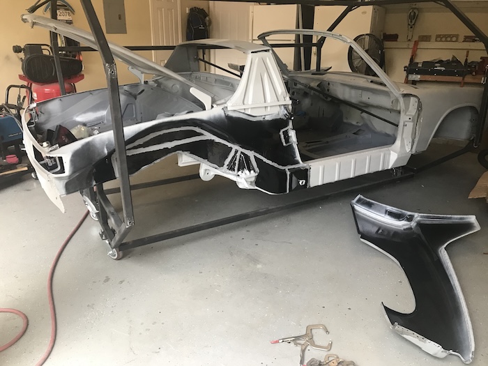 |
|
|
|
|
6 User(s) are reading this topic (6 Guests and 0 Anonymous Users)
0 Members:

|
Lo-Fi Version | Time is now: 7th April 2026 - 07:42 AM |
Invision Power Board
v9.1.4 © 2026 IPS, Inc.