

 Rust repair before paint, Front of the passenger long - 73 narrow body/4, now 6 conversion rebuild thread Rust repair before paint, Front of the passenger long - 73 narrow body/4, now 6 conversion rebuild thread |
|
|

|
Porsche, and the Porsche crest are registered trademarks of Dr. Ing. h.c. F. Porsche AG.
This site is not affiliated with Porsche in any way. Its only purpose is to provide an online forum for car enthusiasts. All other trademarks are property of their respective owners. |
|
|
  |
| 930cabman |
 May 31 2026, 06:07 AM May 31 2026, 06:07 AM
Post
#241
|
|
Advanced Member  Group: Members Posts: 4,810 Joined: 12-November 20 From: Buffalo Member No.: 24,877 Region Association: North East States 
 |
QUOTE(Montreal914 @ May 30 2026, 08:56 PM)  QUOTE(worn @ May 30 2026, 05:36 PM) I use my 3.2 for pretty long drives and really like having a sleeper narrow body with 205 tires. One thing that I really like is that I have tall 4th and 5th gears. Fifth is a flipped HB from the doctor. Lopes along even when the speed limit is 85. What a feeling with sun coming up behind me, the Rockies ahead and the road in between. @worn Yes, I have read this in one of your post. I would be curious to know what is your entire gearset. As we know the problem with the 901 is the captive 2nd gear (F) wich is too low and therefore first (A) also too low. The GA shaft is better, but a 904 shaft really open the doors. If I ever buy a 904 shaft, I have an HA 2nd which is getting close to the ratio used in the 911 with the 3.2. This would allow to have a taller 5th gear without having a big step. Although the limit is 65 in my area, most of the people drive around 80 which seems fine to me. This would mean about 3400 RPM. Not sure what is a good highway engine speed so it is happy and cool. (IMG:style_emoticons/default/confused24.gif) If you look at the graphs, the ZD is actually pretty close to the 911s. About 5000rpm (give or take) at 120 mph. semi off topic, my 2056 with (from what I know) stock gearing is happy at 3200 - 3400 rpms. Runs around 220F oil temp and gets great gas mileage |
   |

 
|
| nivekdodge |
May 31 2026, 07:39 PM
Post
#242
|
|
Member Group: Members Posts: 340 Joined: 28-August 21 From: Pittsburgh Pa Member No.: 25,860 Region Association: MidAtlantic Region
|
Wow that's coming around like all get out
kevin |
|
|
|
| worn |
Jun 2 2026, 06:11 PM
Post
#243
|
|
Winner of the Utah Twisted Joint Award Group: Members Posts: 3,647 Joined: 3-June 11 From: Madison, WI and North Bend WA Member No.: 13,152 Region Association: Upper MidWest
|
QUOTE(Montreal914 @ May 30 2026, 07:56 PM) QUOTE(worn @ May 30 2026, 05:36 PM) I use my 3.2 for pretty long drives and really like having a sleeper narrow body with 205 tires. One thing that I really like is that I have tall 4th and 5th gears. Fifth is a flipped HB from the doctor. Lopes along even when the speed limit is 85. What a feeling with sun coming up behind me, the Rockies ahead and the road in between. @worn Yes, I have read this in one of your post. I would be curious to know what is your entire gearset. As we know the problem with the 901 is the captive 2nd gear (F) wich is too low and therefore first (A) also too low. The GA shaft is better, but a 904 shaft really open the doors. If I ever buy a 904 shaft, I have an HA 2nd which is getting close to the ratio used in the 911 with the 3.2. This would allow to have a taller 5th gear without having a big step. Although the limit is 65 in my area, most of the people drive around 80 which seems fine to me. This would mean about 3400 RPM. Not sure what is a good highway engine speed so it is happy and cool. (IMG:style_emoticons/default/confused24.gif) If you look at the graphs, the ZD is actually pretty close to the 911s. About 5000rpm (give or take) at 120 mph. For cruising 5,000 mph sounds just a bit loud to me, although I love the sound of the fan and intake right behind my right ear. I remember the flipped HB. Have to look back for notes about fourth gear. I remember that both fourth and fifth were overdrive. I did a set of repairs of hell hole floors firewall and trunk like your project. I haven’t updated the posts, but it is a very nice car after all of that is over. Chasing tuning the MPS for a 2056. |
|
|
|
| Montreal914 |
Jun 7 2026, 12:55 AM
Post
#244
|
|
Advanced Member Group: Members Posts: 2,190 Joined: 8-August 10 From: Claremont, CA Member No.: 12,023 Region Association: Southern California
|
Back to the rust... (IMG:style_emoticons/default/rolleyes.gif)
The next step will be to tackle the lower half of the inner long in the portion under the door all the way to the front (lower back corner of the wheel well). This section marked below. This rust is unfortunately more than surface rust. (IMG:style_emoticons/default/dry.gif) 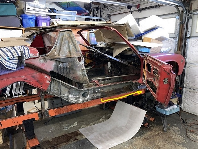 Here we can better see the level of rust in the forward portion. 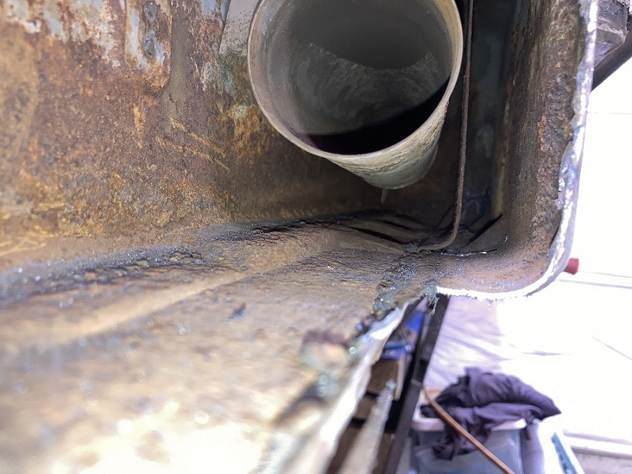 I got my hand on this donor piece but it is far from great, especially in the rear section as seen in this picture. 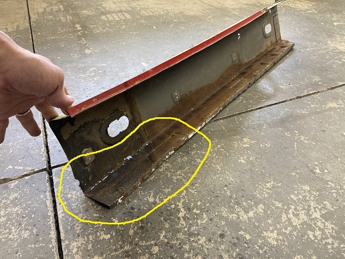 So I cut out this section to repair it. 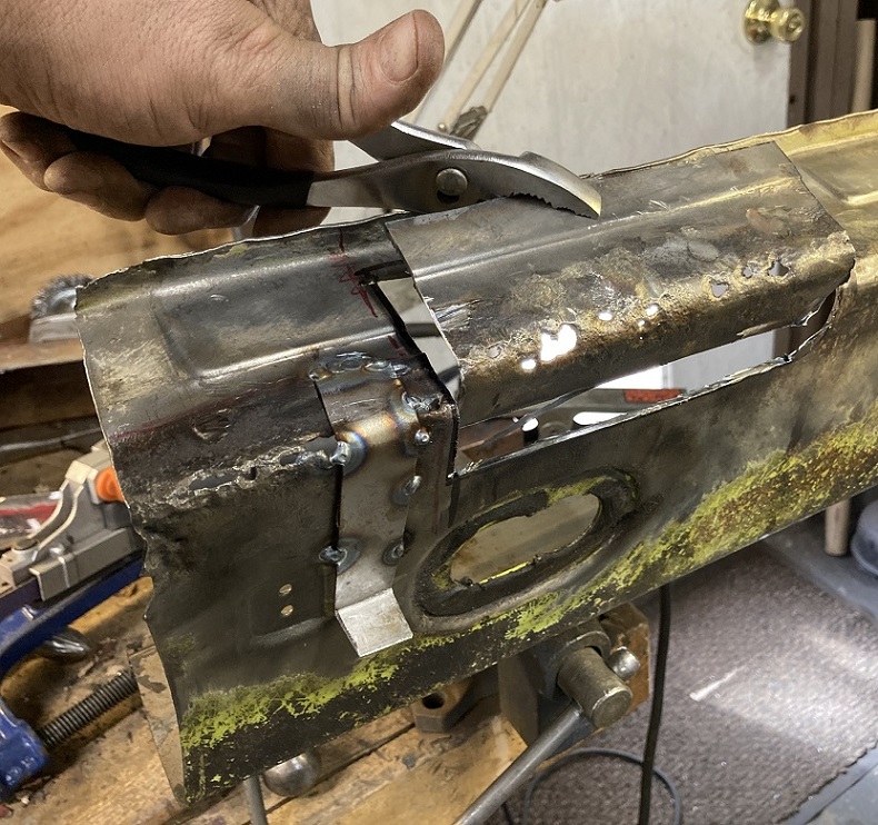 Repaired... (IMG:style_emoticons/default/welder.gif) 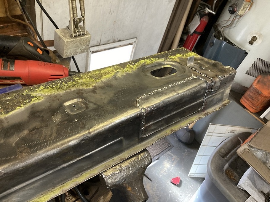 After cleaning up the surface rust, this lower section should work well to address the rusted area on the car. 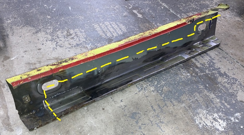 Now before going all in, this is where some planning has to happen. (IMG:style_emoticons/default/idea.gif) In post #51, I had bent aluminum tubes to create lines for the front cooler. Here: http://www.914world.com/bbs2/index.php?s=&...t&p=2966460 Since then, this project has now moved on to a six conversion. I plan on redoing the oil lines a little differently at the back since the /4 engine mounts are no longer present, but also at the front. Previously the soft lines were going upwards in the front wheel well and going through the inner fender and eventually in the fuel tank cavity and to the front. I decided to go another route that has been sucessfully used here which is also a mirror image of the GT setup. Instead, the lines go in the cabin by the passergers right foot. So here is the plan. The line will run behind the passenger side rocker panel all the way to the front and bend inward 90 degrees and go in at the very front of the long. This picture shows how they will be routed inside the cabin. There will definitely more details on this in the coming work. Flexible lines are shown in yellow. In black is a nice billet bulkhead part shown in the 2nd picture 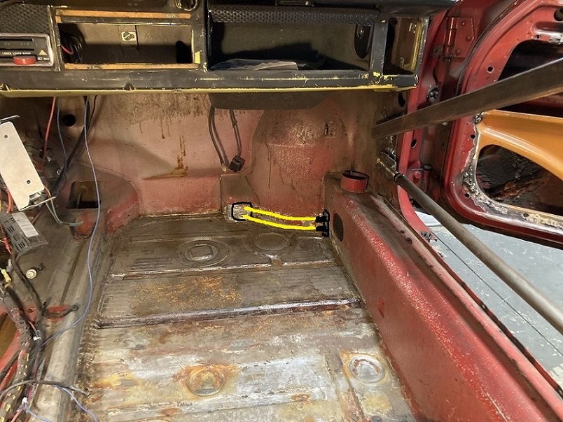 Billet AN12 bulkhead with drill template. 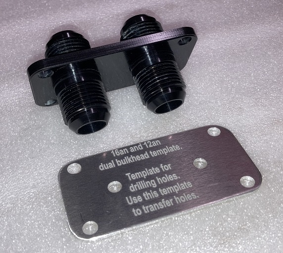 The plan is to build a sealed box to keep the strength of that front lower corner and to prevent oil to make its way in the long in case of a leak. Here is a printout to scale of the lines, fittings and the bulkhead. 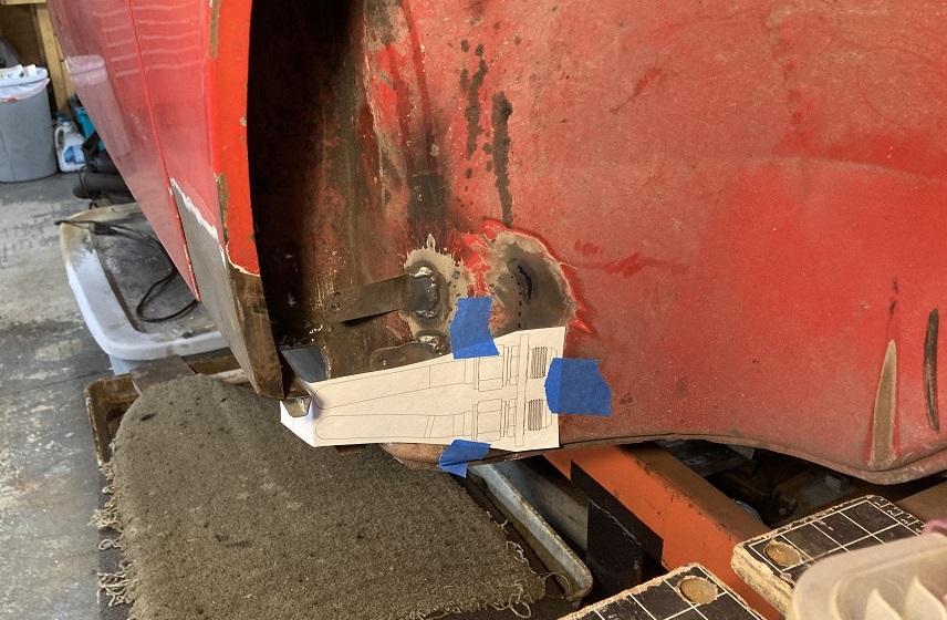 Now on to the preparation of the box that will live in this front radiused area. I first made a template in cartboard to properly fit in that lower corner. The radius seen in the front sits right behind the wheel well lower back wall but inside that cabin. The bulkhead aluminum template shows where the bulkhead part will be installed. 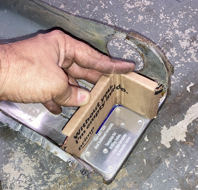 Cardboard tranferred to a metal sheet. 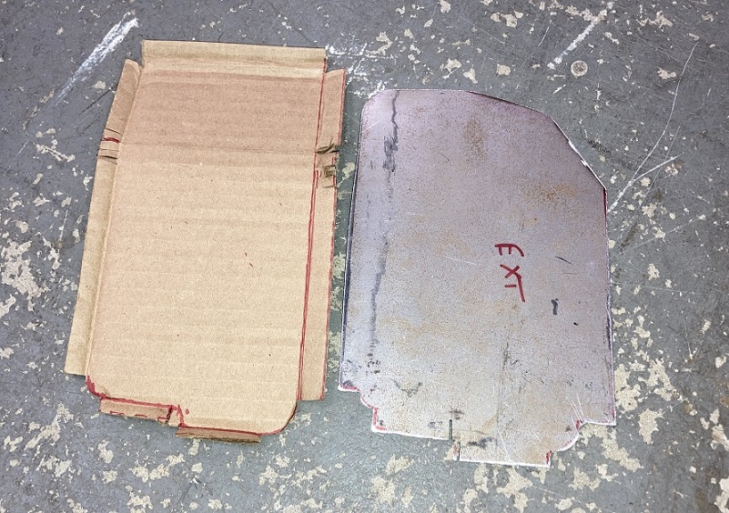 More fabrication using proven technique. (IMG:style_emoticons/default/smash.gif) 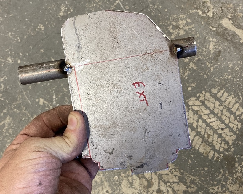 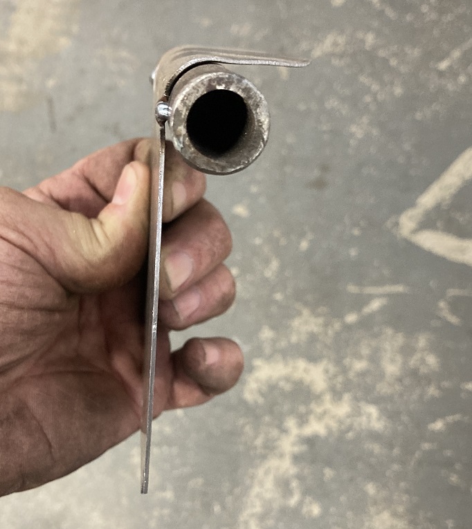 And after some more work, The partition creating the box is completed. (IMG:style_emoticons/default/smile.gif) 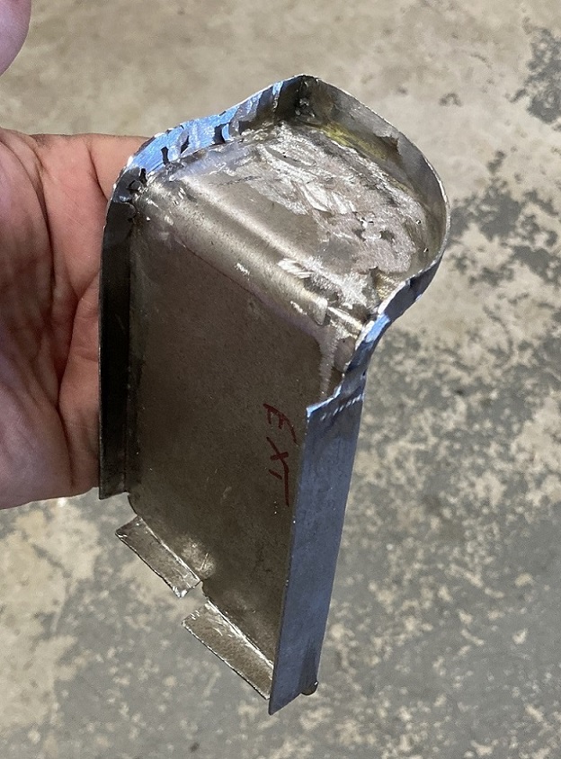 Now placed in the front of the long where it will be later welded. You can aslo see the bulkhead fitting template. This will keep that corner strong even though there will be openings done for the lines to go in. (IMG:style_emoticons/default/sunglasses.gif) 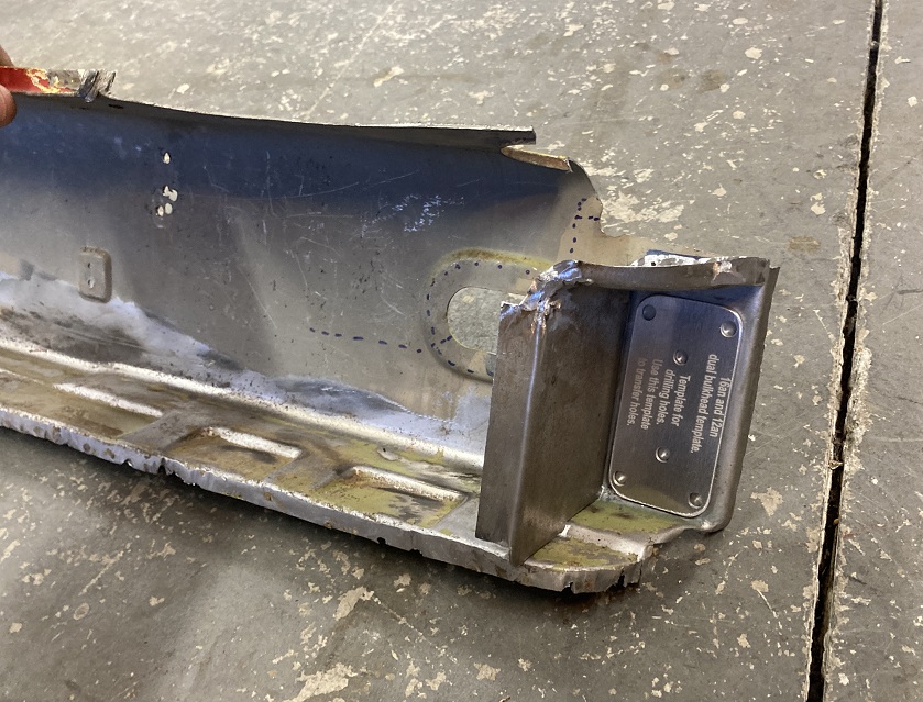 Now this box comes at a cost. There is a heating steel elbow that normally lives there. Unfortunately, this one will need to be altered in order to clear the box. Here we can see that I remove the bottom flange and weded the bottom area shut. This may help with the reinstallation of the tube. Also, I cut a notch that will clear the box once the elbow is in place. 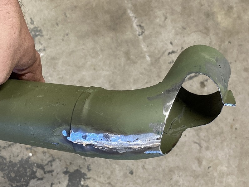 Now the preparation of the patch that will close this large opening. 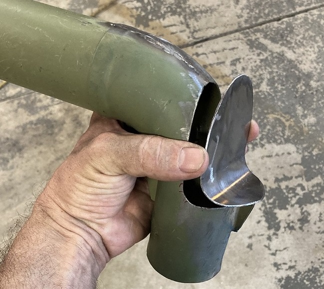 And now all welded and ready for fit test. It looks extremely happy! (IMG:style_emoticons/default/laugh.gif) 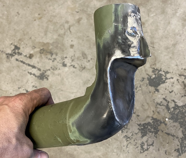 And the final mock up. The notched elbow has at least 1/4" clerance from the box partition. This whole thing will require some sequence planning for its wedling on the car but that is all upcoming work. (IMG:style_emoticons/default/smash.gif) (IMG:style_emoticons/default/welder.gif) 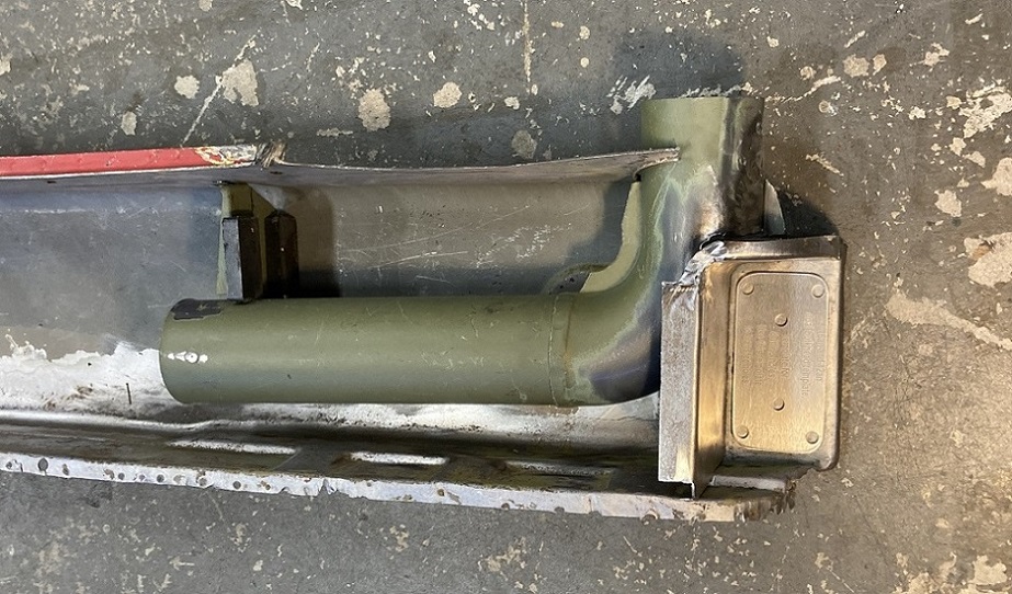 |
|
|
|
| mepstein |
Jun 7 2026, 04:56 AM
Post
#245
|
|
914-6 GT in waiting Group: Members Posts: 20,889 Joined: 19-September 09 From: Landenberg, PA/Wilmington, DE Member No.: 10,825 Region Association: MidAtlantic Region
|
Amazing amount of work. (IMG:style_emoticons/default/beerchug.gif)
|
|
|
|
| friethmiller |
Jun 7 2026, 06:18 AM
Post
#246
|
|
Senior Member Group: Members Posts: 1,501 Joined: 10-February 19 From: Austin, TX Member No.: 22,863 Region Association: Southwest Region
|
I smile inside when I see this type of cardboard fabrication. Keep up the great work! (IMG:style_emoticons/default/popcorn[1].gif)
|
|
|
|
| 930cabman |
Jun 7 2026, 04:00 PM
Post
#247
|
|
Advanced Member Group: Members Posts: 4,810 Joined: 12-November 20 From: Buffalo Member No.: 24,877 Region Association: North East States
|
Ah, the custom work is where the fun exists
lookin great, is there an ETA |
|
|
|
| Montreal914 |
Jun 7 2026, 04:22 PM
Post
#248
|
|
Advanced Member Group: Members Posts: 2,190 Joined: 8-August 10 From: Claremont, CA Member No.: 12,023 Region Association: Southern California
|
QUOTE(friethmiller @ Jun 7 2026, 05:18 AM) I smile inside when I see this type of cardboard fabrication. Keep up the great work! (IMG:style_emoticons/default/popcorn[1].gif) If you look closely, you will see I actually used both the analog (cardboard) and numerical (computer) aided design - CAD. (IMG:style_emoticons/default/laugh.gif)QUOTE(930cabman @ Jun 7 2026, 03:00 PM) Ah, the custom work is where the fun exists I fully agree, fixing the rust isn't very pleasant but engineering custom solutions is definitely more stimulating.lookin great, is there an ETA No ETA, hopefully before I am 60 (currently 57)! (IMG:style_emoticons/default/laugh.gif) |
|
|
|
| Montreal914 |
Jun 14 2026, 11:32 AM
Post
#249
|
|
Advanced Member Group: Members Posts: 2,190 Joined: 8-August 10 From: Claremont, CA Member No.: 12,023 Region Association: Southern California
|
Weekend update and work documentation. (IMG:style_emoticons/default/smile.gif)
It is a lot easier to work on a bench/floor than on a chassis, therefore I continued the preparation of the replacement panel for the installation of the -12AN billet dual bulkhead fitting shown in the previous post. Since I will be reinforcing the chassis with a Maddogs inner kit (as already seen on the driver's side restoration), I coupled it to the donor piece so I could drill the fitting mounting holes in both layers simultaneously, ensuring the proper alignment. Clamping and self tapping screws to temporarily join both pieces. 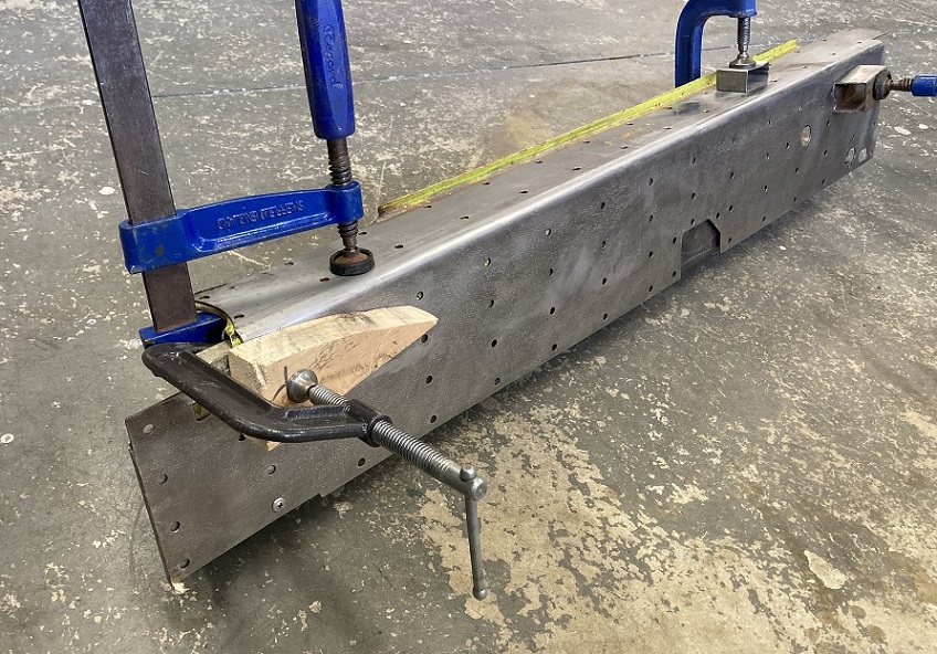 And a final check before drilling. Using the provided drilling template I marked the holes on the metal. Check twice, drill once! (IMG:style_emoticons/default/smash.gif) 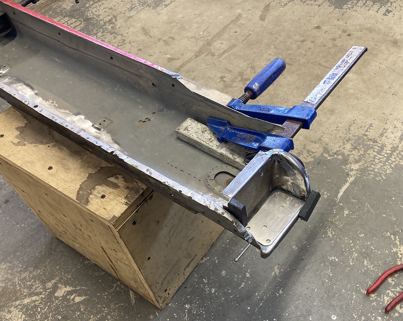 Onto my $50 Craigslist drill press. 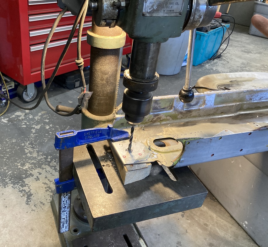 All the holes are now drilled. The larger ones for the actual fittings were achieved with a knock out punch after the two pilot holes were done on the drill press. 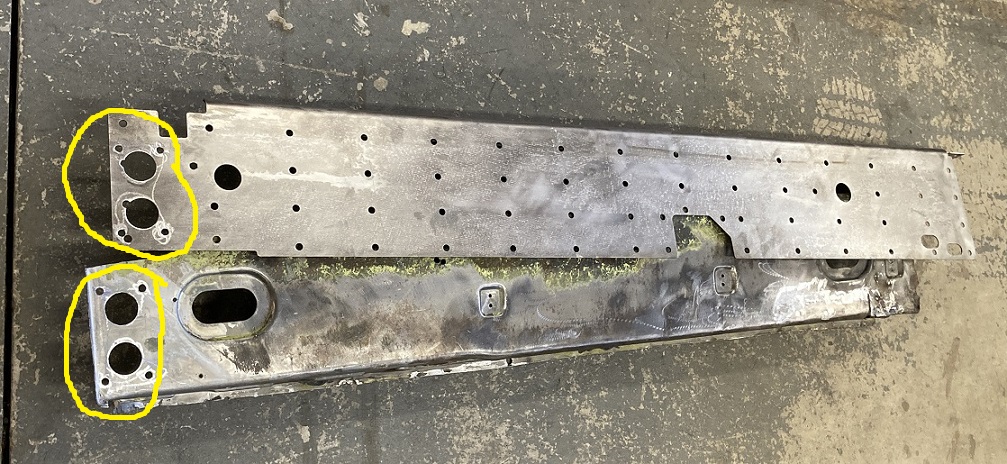 And now the final preassembly with the -12 bulkhead fitting flange. (IMG:style_emoticons/default/smile.gif) 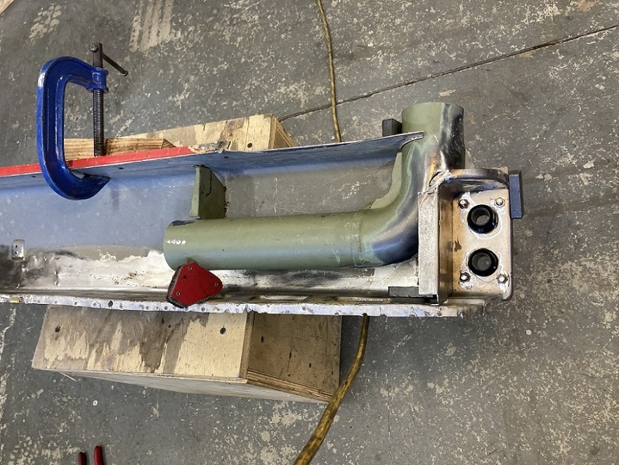 Another angle showing the gap between the custom made partition and the modified elbow duct. 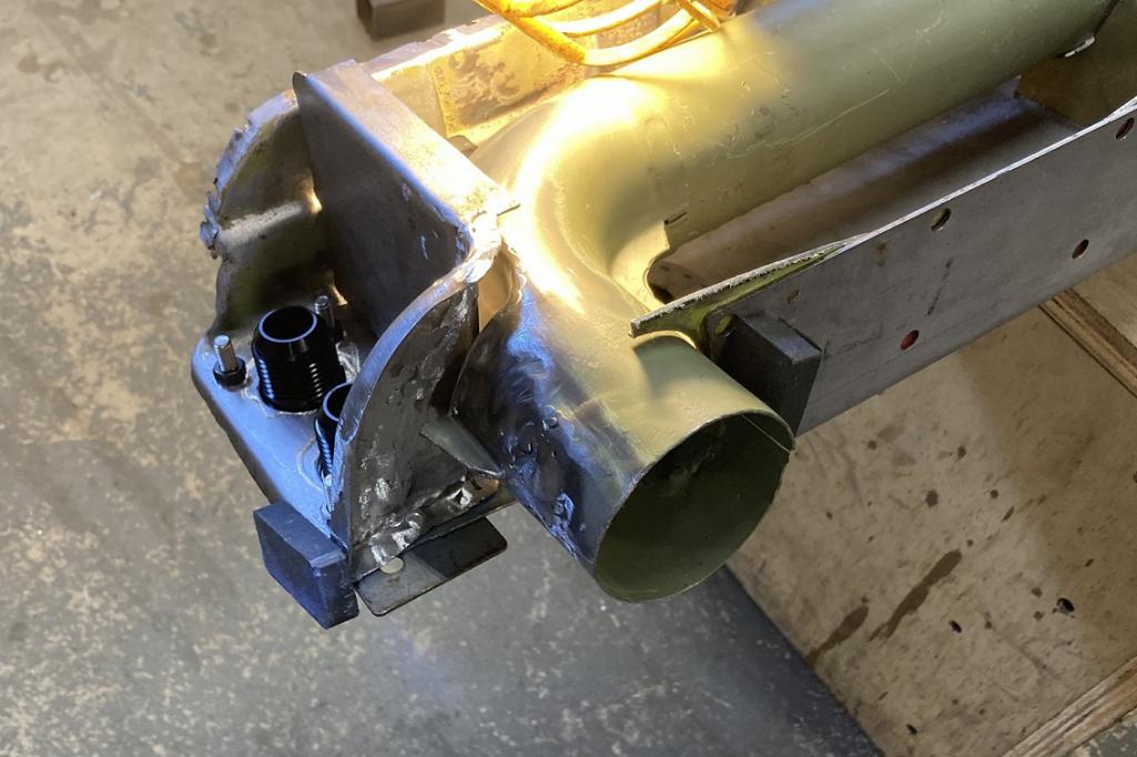 Last, I welded four M6 nuts on the inside of the channel for an easier installation of the fitting flange on the car upon assembly. 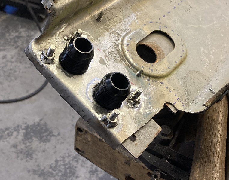 Next step, I removed the existing elbow duct currently on the car. 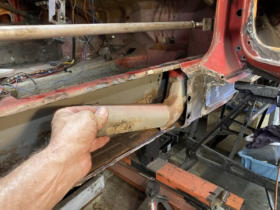 No big surprise here. (IMG:style_emoticons/default/dry.gif) Looking forward where the ebow duct used to be, the lower half is pretty pitted with rust. All of the inside lower portion will be coming out and be replaced by the prepared pieces. 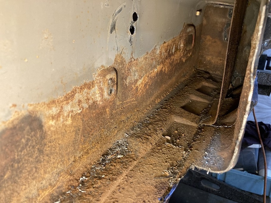 Before cutting metal out, I tacked a temporary diagonal piece to keep the relation between the under seat cross member and the passenger longitudinal since these two will get disconnected in the upcoming cutting process. 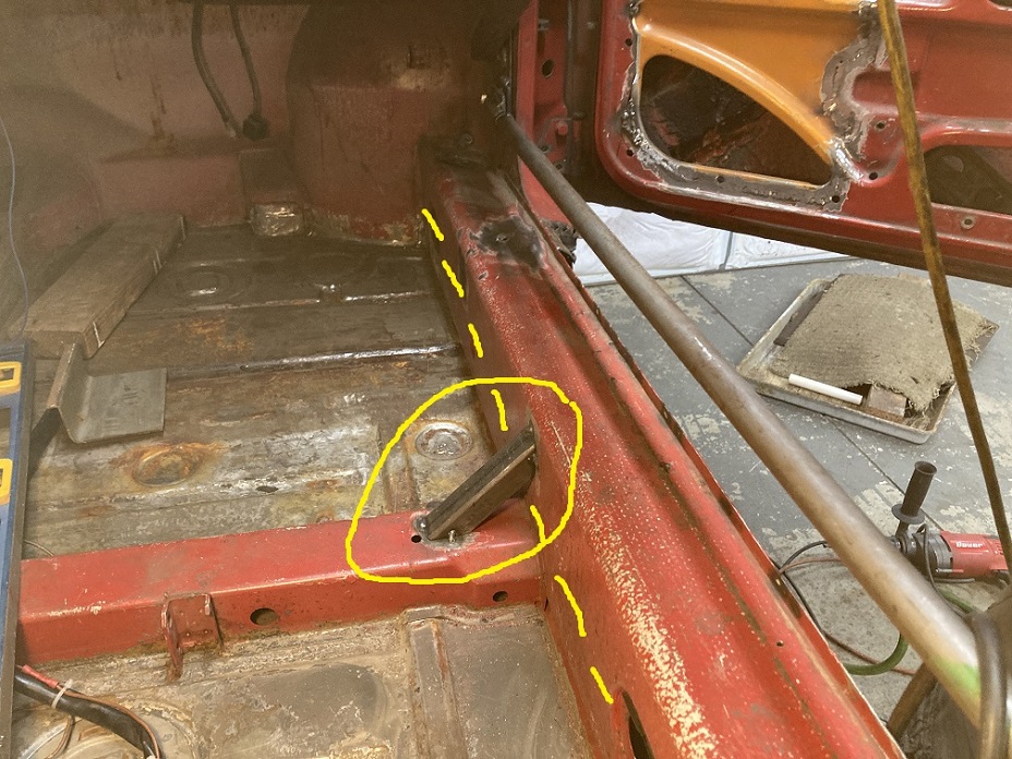 And the cutting begins! (IMG:style_emoticons/default/sawzall-smiley.gif) 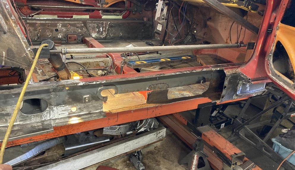 And crusty metal out! 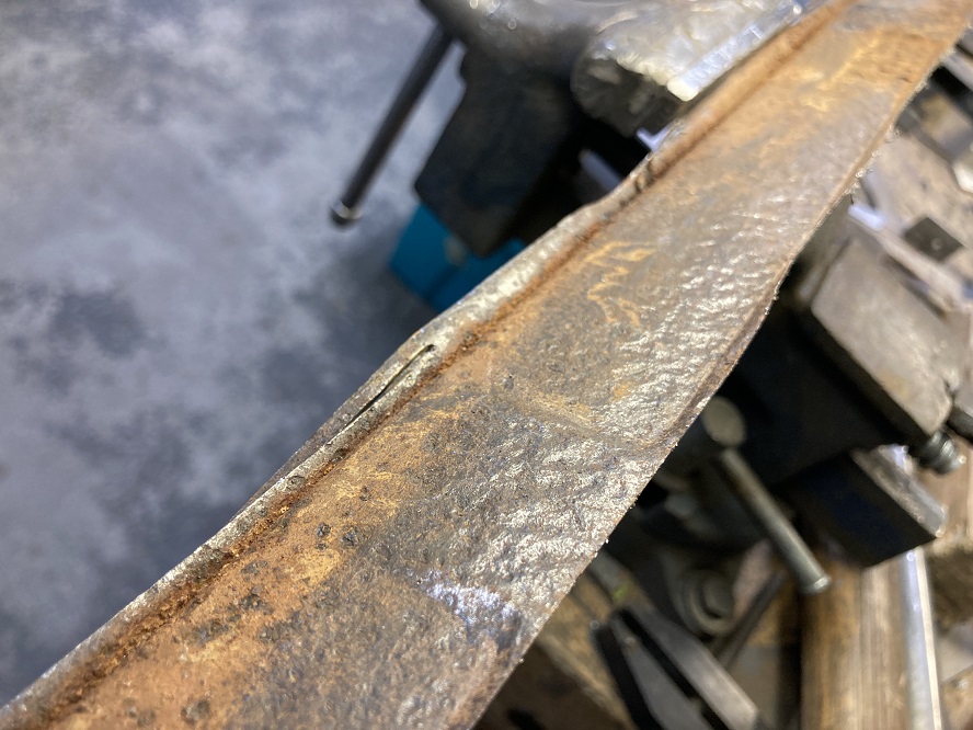 Rough cutting completed. Floor pan flange cleanup process ongoing. (IMG:style_emoticons/default/smash.gif) No movement of the chassis, dimension survey is the same including the 25 1/8" for the top of windshield to roll bar. 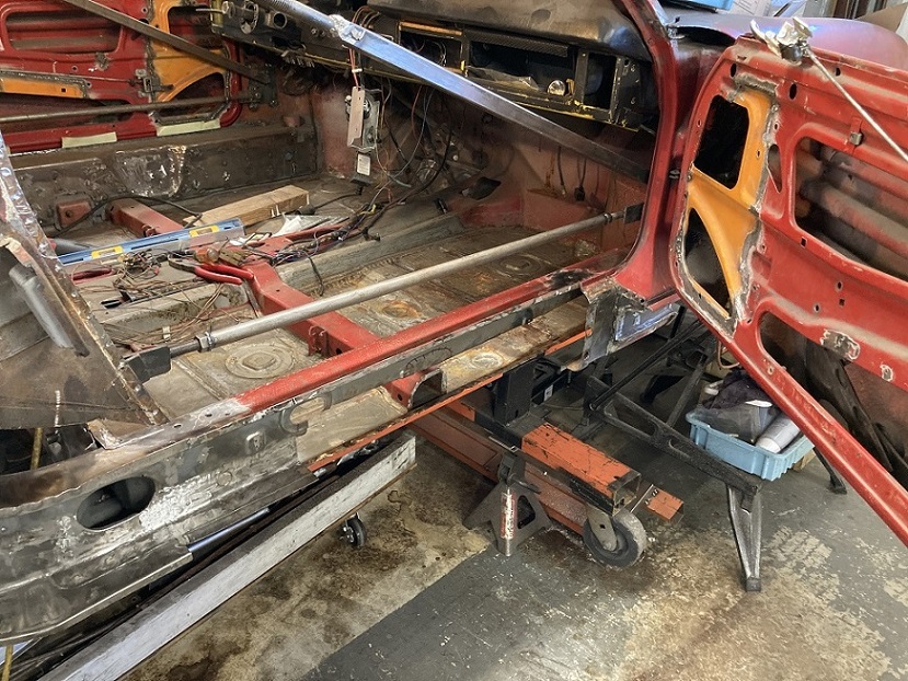 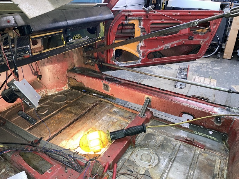 That is the current state of work. More to come! (IMG:style_emoticons/default/smile.gif) |
|
|
|
| Montreal914 |
Jun 28 2026, 09:29 PM
Post
#250
|
|
Advanced Member Group: Members Posts: 2,190 Joined: 8-August 10 From: Claremont, CA Member No.: 12,023 Region Association: Southern California
|
More cleaning-up of that front area of the long. (IMG:style_emoticons/default/smash.gif)
I am using my small submercible pump to flush citric acid on this inner partition which is actually the prolongation of the inner fender that bends around towards the back to create a strong area as part of the door post and transition to the longitudinal beam. Here we are looking towards the front from within the long. The floor pan is obvious and the remaining upper half of the inner long is on the top left of the picture. Black arrow shows the citric acid flush Yellow arrow the inner fender extension Red arrow is the inner rocker (the outside layer of the long) 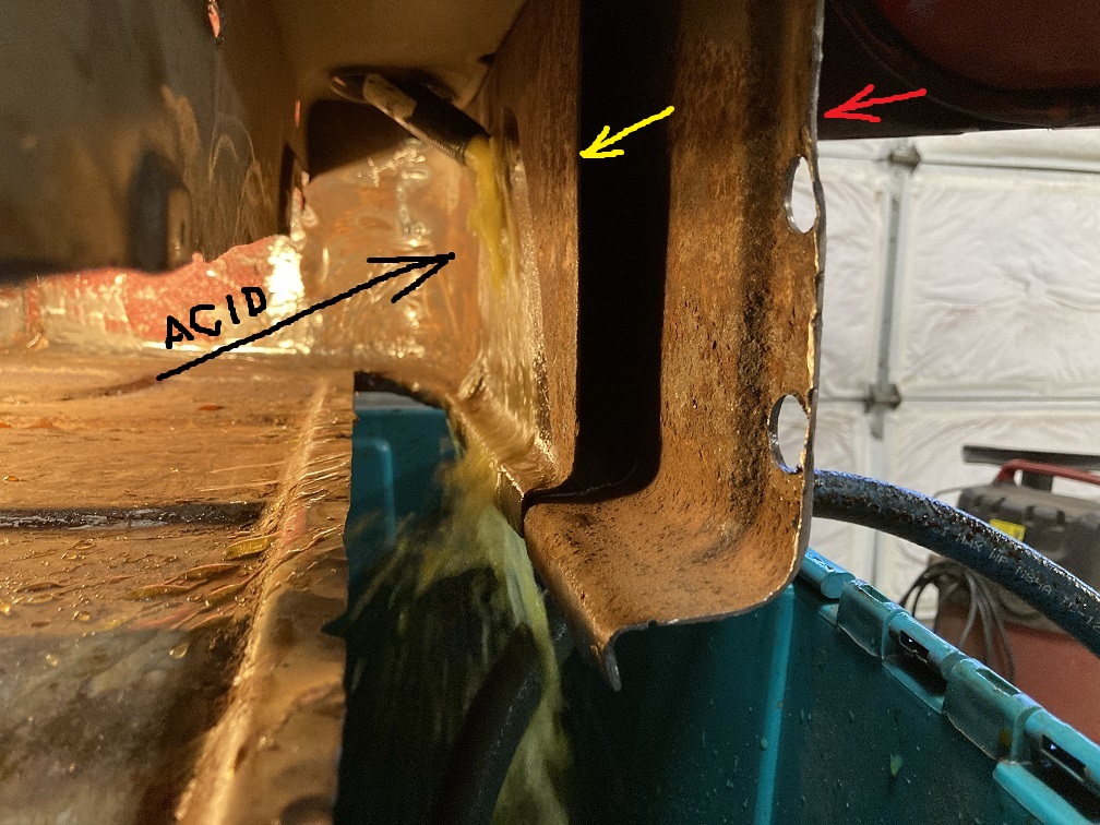 And here is what the acid cleaned up after about 12h. This is not a fast process but at the same time, it allows to gradually see the progress. The hose is then moved to flush other areas. 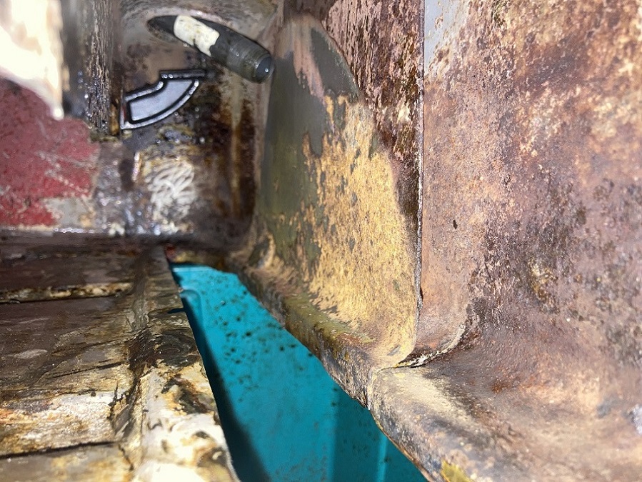 Moving on to the opening for the oil lines in the lower corner of the inner fender. That radiused corner is the metal layer that extends towards the back and becomes that partition that I was flushing with acid in the previous pictures. Using my knockout punch (what a great tool), I am opening up the four holes that will create the opening. 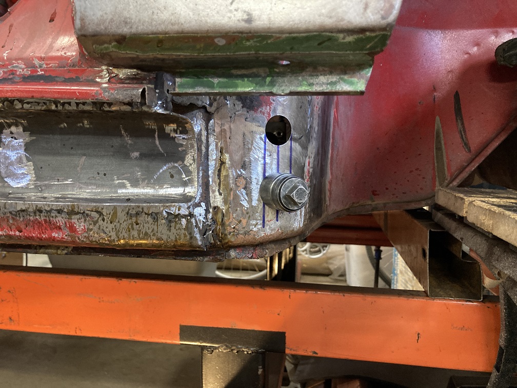 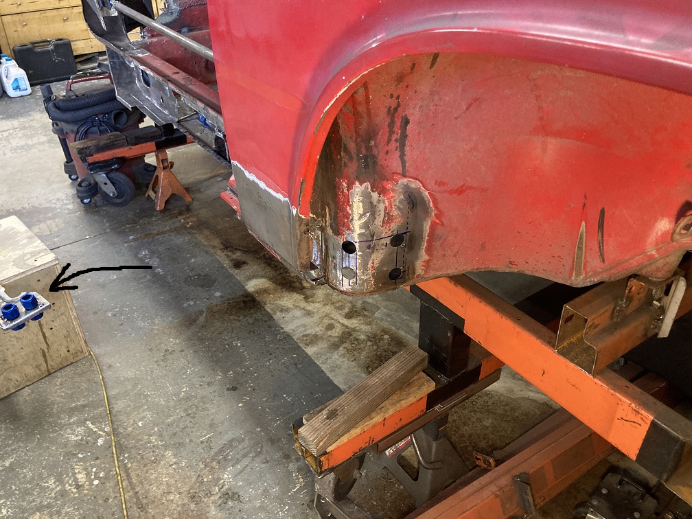 After validating (long process... (IMG:style_emoticons/default/rolleyes.gif) ) that everything fits properly and it can actually be installed from the inside in that corner, I tacked the custom piece I showed in the previous post to the inner long repair piece. This will create a nice solid box in the oil lines connection area and should maintain a good structural integrety of that front corner, even if it is cut out. 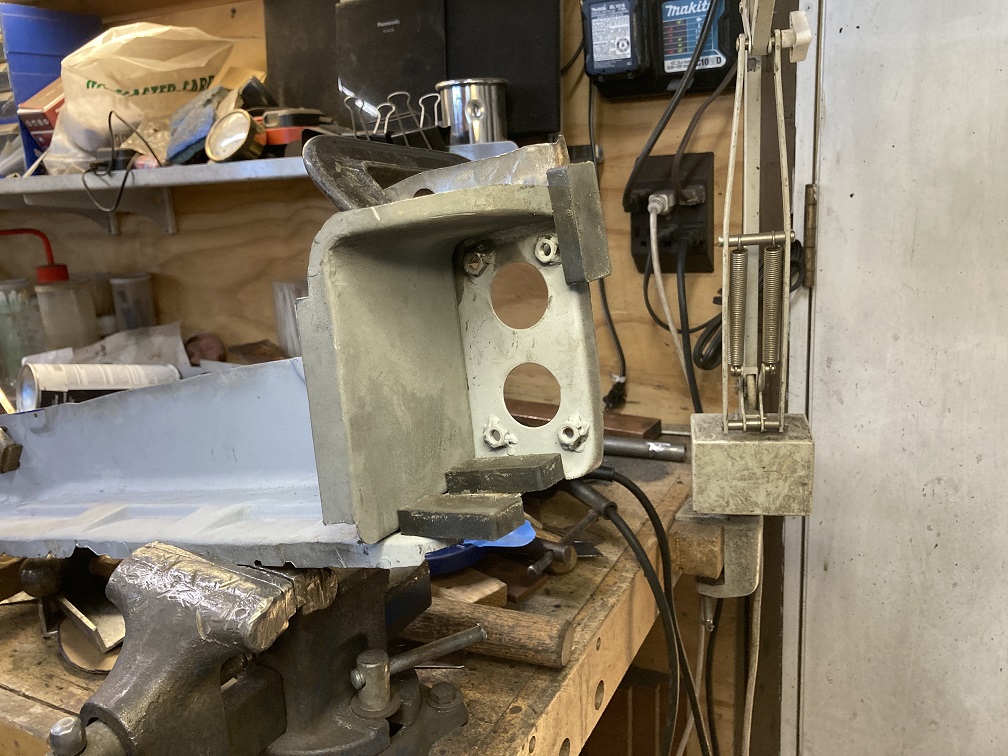 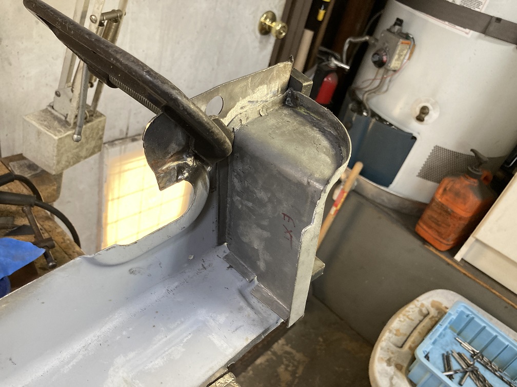 Looking at the lower right corner of the passenger footwell, here is the long repair piece set in place and held with magnets. We can see the double bulkhead flange AN fittings bolted to the long and what it will look like once all welded in place. Arrow points to the custom box piece and shows how nicely it rest against the inner partition I was derusting earlier. 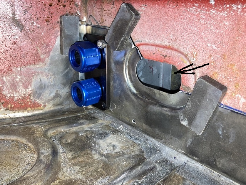 Here is a different angle of the situation. Looking through the port where the heater duct elbow will live, arrows are pointing to the fit of the custom box to the back side of the inner fender. (IMG:style_emoticons/default/smile.gif) 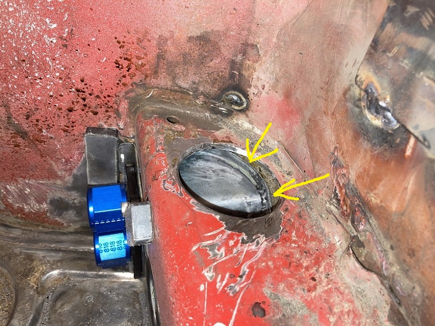 Finally, looking at the area of interest where the oil lines will come along the outside of the long, bend 90 degrees towards the inside and connect to the double flanged AN fittings. 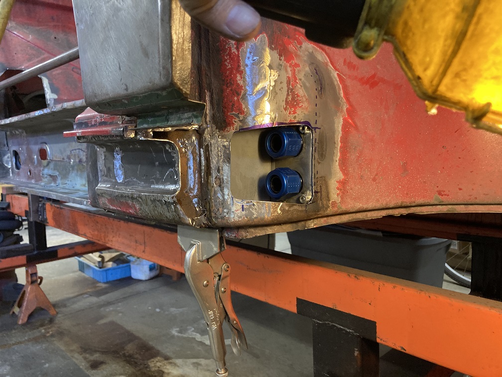 Another angle where we can see the box nicely fitted and closing the inside of the long. This is just trial fit, nothing is welded at this point other than the box L piece which is tacked to the inner long repair piece. 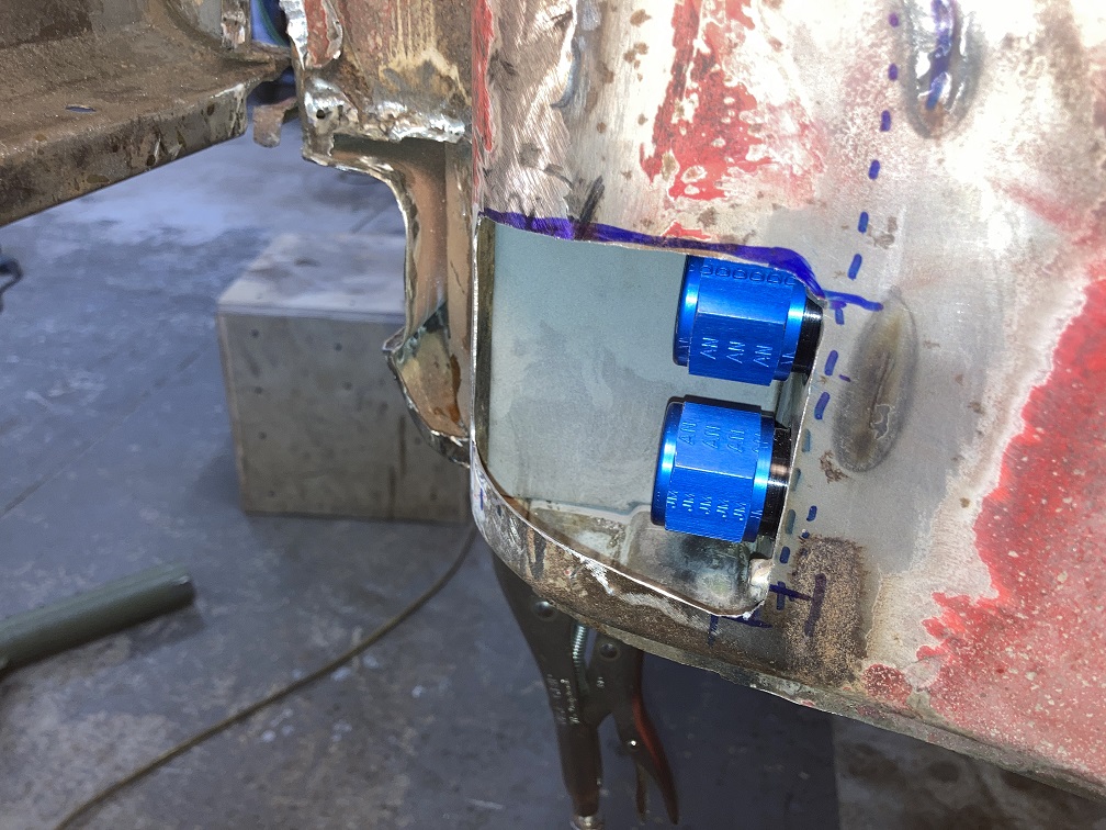 Another check is making sure my crow foot will actually fit in there and allow me to tighten the lines upon installation. 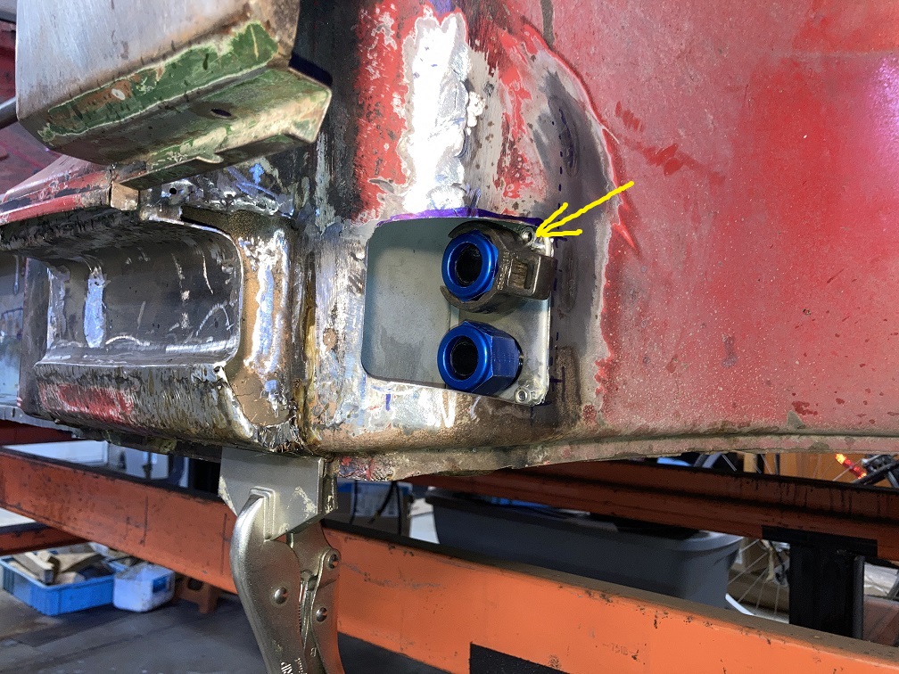 Still a lot more work to happen in this area. (IMG:style_emoticons/default/smash.gif) but this is looking promising. Very pleasant for a vision to become reality. I guess this is a big part of the journey. (IMG:style_emoticons/default/smile.gif) |
|
|
|
| Cairo94507 |
Jun 29 2026, 07:10 AM
Post
#251
|
|
Michael Group: Members Posts: 10,753 Joined: 1-November 08 From: Auburn, CA Member No.: 9,712 Region Association: Northern California
|
Amazing work - really like the oil line design. (IMG:style_emoticons/default/beerchug.gif)
|
|
|
|
| friethmiller |
Jun 29 2026, 07:22 AM
Post
#252
|
|
Senior Member Group: Members Posts: 1,501 Joined: 10-February 19 From: Austin, TX Member No.: 22,863 Region Association: Southwest Region
|
My favorite build thread! (IMG:style_emoticons/default/popcorn[1].gif) I enjoy watching the work progress. Keep it up! (IMG:style_emoticons/default/beer.gif)
|
|
|
|
| DennisV |
Jun 29 2026, 07:24 AM
Post
#253
|
|
Senior Member Group: Members Posts: 1,029 Joined: 8-August 20 From: Santa Rosa, CA Member No.: 24,575 Region Association: Northern California
|
QUOTE(Montreal914 @ Jun 6 2026, 11:55 PM) Here is a printout to scale of the lines, fittings and the bulkhead. Great attention to detail. The scale printout is a clever way to mock-up. I don't recall seeing that technique before. Nice. |
|
|
|
| tygaboy |
Jun 29 2026, 07:42 AM
Post
#254
|
|
914 Guru Group: Members Posts: 5,848 Joined: 6-October 15 From: Petaluma, CA Member No.: 19,241 Region Association: Northern California
|
Wow. REALLY, really great work and attention to detail. I love when effort is put into areas that no one will ever see. That right there is "craftsmanship".
I'm inspired! It almost makes me want to get started on the rusty 914 I have... almost. (IMG:style_emoticons/default/laugh.gif) |
|
|
|
| HFC3 |
Jun 29 2026, 08:11 AM
Post
#255
|
|
Member Group: Members Posts: 138 Joined: 14-December 25 From: Virginia Member No.: 29,151 Region Association: MidAtlantic Region |
Great build!
|
|
|
|
| 930cabman |
Jun 29 2026, 09:56 AM
Post
#256
|
|
Advanced Member Group: Members Posts: 4,810 Joined: 12-November 20 From: Buffalo Member No.: 24,877 Region Association: North East States
|
The stuff we get accomplished on these buggies is incredible (IMG:style_emoticons/default/piratenanner.gif)
real craftsmanship here, thanks for documenting |
|
|
|
| nivekdodge |
Jun 30 2026, 07:49 PM
Post
#257
|
|
Member Group: Members Posts: 340 Joined: 28-August 21 From: Pittsburgh Pa Member No.: 25,860 Region Association: MidAtlantic Region
|
I see it and want to start over with #1 but only better. Excellent work.
Kevin |
|
|
|
|
1 User(s) are reading this topic (1 Guests and 0 Anonymous Users)
0 Members:

|
Lo-Fi Version | Time is now: 3rd September 2026 - 03:07 AM |
Invision Power Board
v9.1.4 © 2026 IPS, Inc.