|
|
|
Porsche, and the Porsche crest are registered trademarks of Dr. Ing. h.c. F. Porsche AG.
This site is not affiliated with Porsche in any way. Its only purpose is to provide an online forum for car enthusiasts. All other trademarks are property of their respective owners. |
|
|

  |

| Montreal914 |
 May 1 2021, 03:55 PM May 1 2021, 03:55 PM
Post
#41
|
|
Advanced Member  Group: Members Posts: 2,112 Joined: 8-August 10 From: Claremont, CA Member No.: 12,023 Region Association: Southern California |
QUOTE(Root_Werks @ Apr 26 2021, 02:24 PM)  Really like this thread! You've got some skills, inspiring! Thank you. (IMG:style_emoticons/default/smile.gif) I am happy with most (IMG:style_emoticons/default/rolleyes.gif) of my work's results. Although this is my first attempt in this kind of work, I owe it to my dad who taught me my hands-on and mechanical skills. The year I was born, he began building a trimaran sailboat from a set of Australian plans in hopes of taking us sailing in the Bahamas. 8 years later, in '78, We towed the boat driving from Montreal to Miami, set it to sea and went discovering the Bahamian islands on this lightweight flying machine! In a way, similar ideology with our beloved 914; very light and nimble. (IMG:style_emoticons/default/sunglasses.gif) 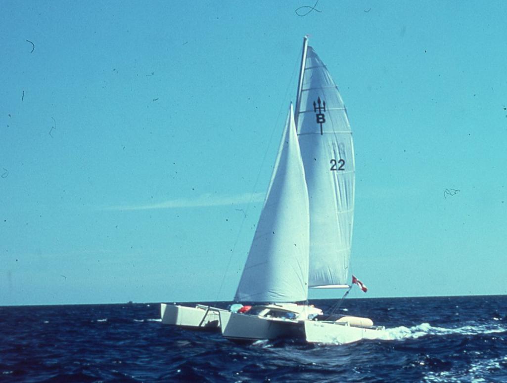 |
   |

 
|
| Montreal914 |
May 1 2021, 04:00 PM
Post
#42
|
|
Advanced Member Group: Members Posts: 2,112 Joined: 8-August 10 From: Claremont, CA Member No.: 12,023 Region Association: Southern California |
Now back to the main program...
Removing the carpet on the driver's side long, I noticed the classic crack on the hand brake area. The car currently has a Brad Mayer stiffening kit on the outside. 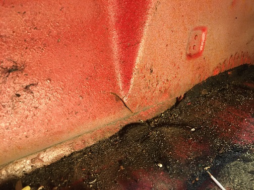 What is the recommended method to fix this? Simply weld up, cut the area and replace with fresh metal, weld and double up with a extra layer? (IMG:style_emoticons/default/confused24.gif) |
|
|
|
| bbrock |
May 1 2021, 06:02 PM
Post
#43
|
|
914 Guru Group: Members Posts: 5,269 Joined: 17-February 17 From: Montana Member No.: 20,845 Region Association: Rocky Mountains |
I just got caught up. Fantastic work. I'm enjoying getting to ride along.
Now I have to ask, where is that boat now? That is epic! |
|
|
|
| Montreal914 |
May 1 2021, 09:25 PM
Post
#44
|
|
Advanced Member Group: Members Posts: 2,112 Joined: 8-August 10 From: Claremont, CA Member No.: 12,023 Region Association: Southern California |
QUOTE(bbrock @ May 1 2021, 05:02 PM) I just got caught up. Fantastic work. I'm enjoying getting to ride along. Now I have to ask, where is that boat now? That is epic! @bbrock ; I am not sure of the current condition of the 24' long x 19' wide little trimaran made out of 3/16" thick plywood. I will ask him if he has fresh news from the new owners. In the early '80s, my dad traded it with extra money for a home built fiberglass foam sandwich 39' x 20' catamaran with a 45' mast from the same Australian designer. That one weighted 8,000lbs, which is still very light weight and very quick for that size sail boat. We enjoyed it as he improved it over the course of many years. He sold it a few years ago, as the maintenance and the navigation became too much for my parents who are now in their 80s. Below, picture taken in 2009 of him with our two daughters, a few month before our move to California. This was on lake Champlain upstate New York near the Canadian border. 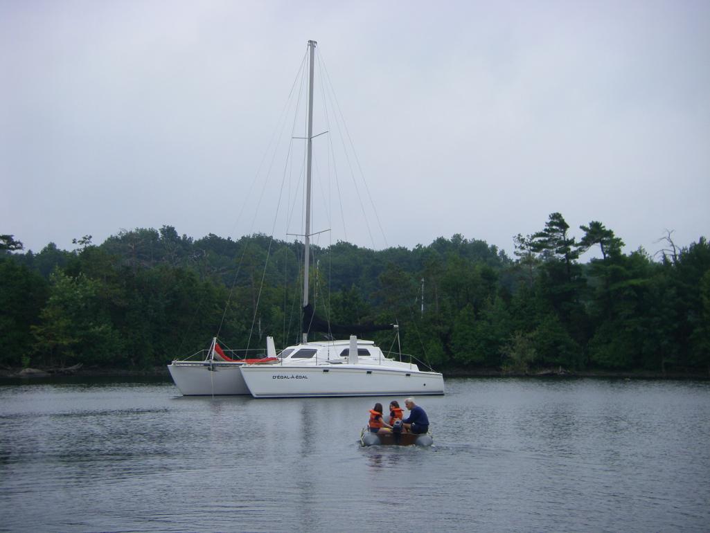 All this nautical distraction is very nice, but we are here to share about 914s (IMG:style_emoticons/default/biggrin.gif) So, what is the consensus on fixing the crack on the driver side inner long... (IMG:style_emoticons/default/idea.gif) |
|
|
|
| bbrock |
May 1 2021, 10:18 PM
Post
#45
|
|
914 Guru Group: Members Posts: 5,269 Joined: 17-February 17 From: Montana Member No.: 20,845 Region Association: Rocky Mountains |
Thanks for the update on the boat(s). Fantastic.
As for the crack, I'd say just weld it up, especially with the stiffening kit. I had to replace that whole bottom section on mine due to rust. I figure by the time it cracks again, I'll likely be long departed. |
|
|
|
| Montreal914 |
May 1 2021, 11:47 PM
Post
#46
|
|
Advanced Member Group: Members Posts: 2,112 Joined: 8-August 10 From: Claremont, CA Member No.: 12,023 Region Association: Southern California |
QUOTE(bbrock @ May 1 2021, 09:18 PM) Thanks for the update on the boat(s). Fantastic. As for the crack, I'd say just weld it up, especially with the stiffening kit. I had to replace that whole bottom section on mine due to rust. I figure by the time it cracks again, I'll likely be long departed. Yeah, I will do that and maybe add another layer with plug welds. Thanks! (IMG:style_emoticons/default/beerchug.gif) |
|
|
|
| Montreal914 |
Aug 13 2021, 11:35 AM
Post
#47
|
|
Advanced Member Group: Members Posts: 2,112 Joined: 8-August 10 From: Claremont, CA Member No.: 12,023 Region Association: Southern California |
Wow, already about 3 1/2 months since my last post! (IMG:style_emoticons/default/sad.gif)
Well, there was some progress but not as much as I would have hoped for. Next on the list are the trunk hinge base mounting points. The left side one had the captive cylindrical nut detached from the base, and the right side one had been rewelded in the course of the car's life, but not in the correct location. (IMG:style_emoticons/default/dry.gif) Removal of both sides: 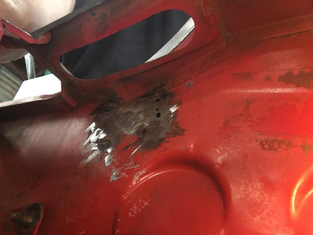 Repair the holes: 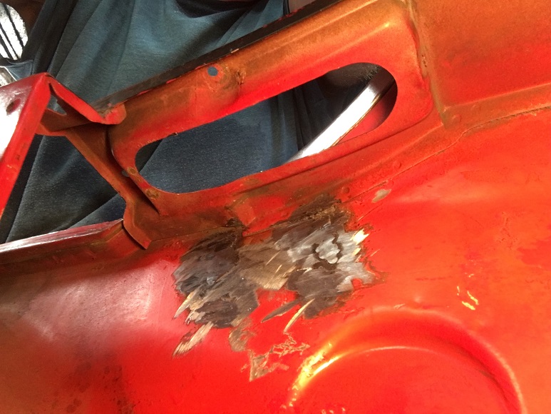 The new hinge base have a couple of good tacks on the back side for the cylindrical nut. But I decided to add some more on the front side... (IMG:style_emoticons/default/biggrin.gif) 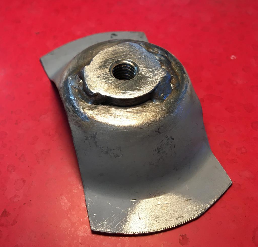 To make sure the new hinge were installed in the right location, I placed the trunk lid on the car, and using sockets as shim in all four corners I adjusted the height and gaps. I also made cross marks on tape to easily reposition it later. 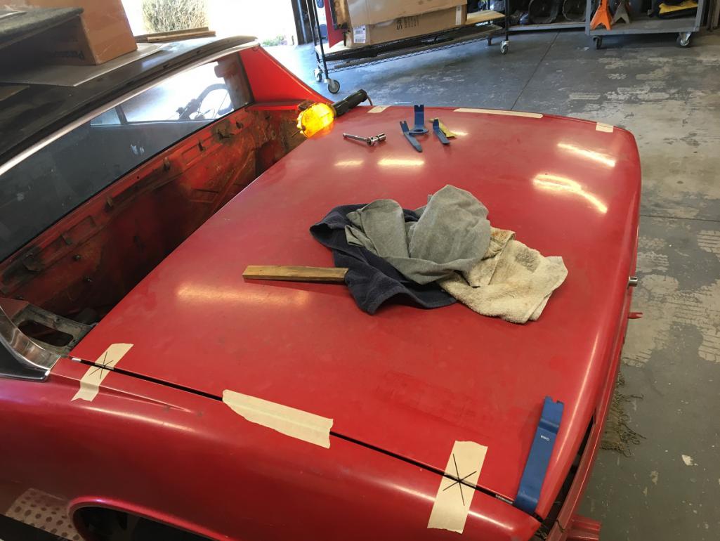 Once happy with the trunk lid alignment and fit, I screwed in the hinge base to the trunk hinge bracket with a new shoulder bolt and marked where it would be set on the body. 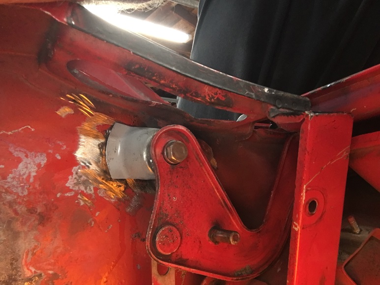 After marking both hinge base to the body, I removed the trunk lid, installed the hinge bases with self tapping screws and installed the lid again for final verification. 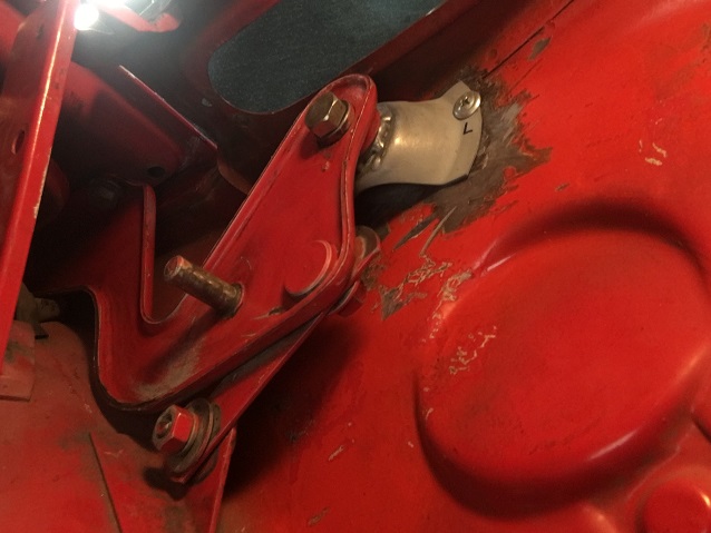 Measure twice weld once (IMG:style_emoticons/default/rolleyes.gif) (IMG:style_emoticons/default/welder.gif) 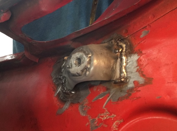 Third trunk lid test install, everything operates smoothly and lines up nice. (IMG:style_emoticons/default/smile.gif) No picture but you get the idea. |
|
|
|
| Montreal914 |
Aug 13 2021, 12:04 PM
Post
#48
|
|
Advanced Member Group: Members Posts: 2,112 Joined: 8-August 10 From: Claremont, CA Member No.: 12,023 Region Association: Southern California |
Time to move on to the engine lid, which also needs help... (IMG:style_emoticons/default/smash.gif)
Typical 914 engine lid bracket issues, both have been repaired, but the passenger side one is broken again. (IMG:style_emoticons/default/dry.gif)  I got a pair of original brackets at one of Bruce Stone's swap meet a while back knowing I was going to need them. These typically fail in two ways: 1- at the bend (like mine) 2- detach from or rip the firewall. Thinking of ways how to prevent this to happen again, at least problem #1, I did this little clearance study: 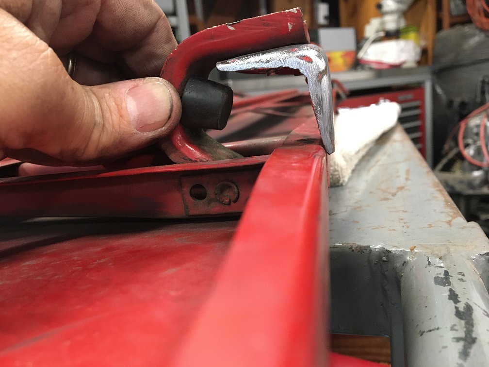 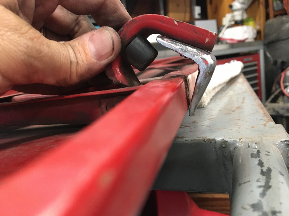 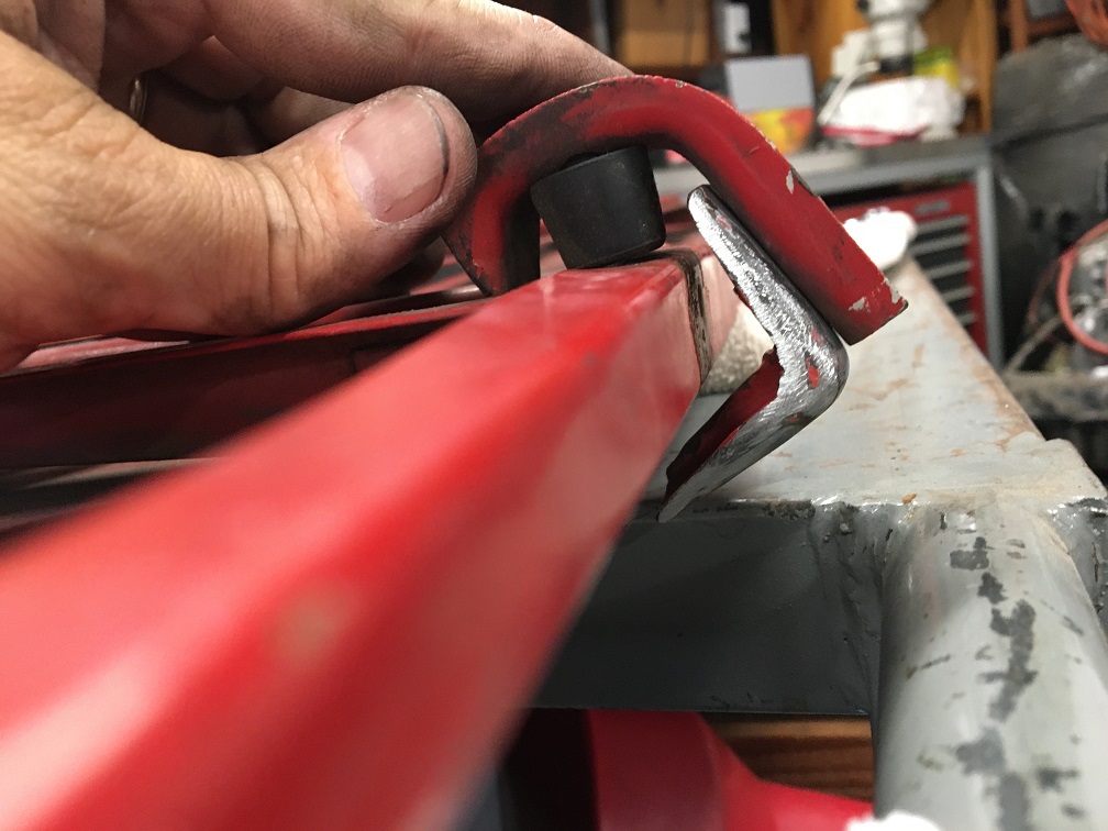 Clearly, there is room on that "L" bracket to add a gusset on each side making it a lot stronger. So here we go! (IMG:style_emoticons/default/smile.gif) 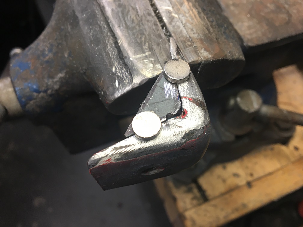 Once done: 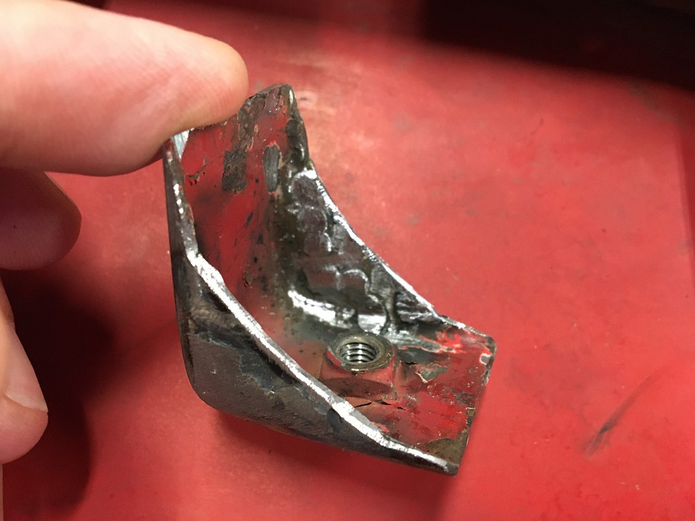 After a little trimming and adjustment, here is the updated clearance study: (IMG:style_emoticons/default/smile.gif) 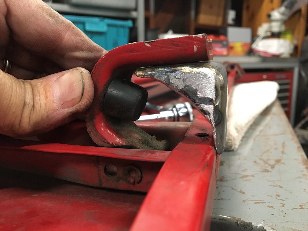 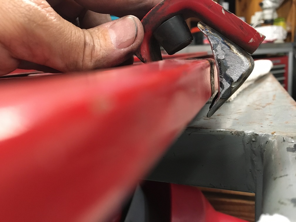 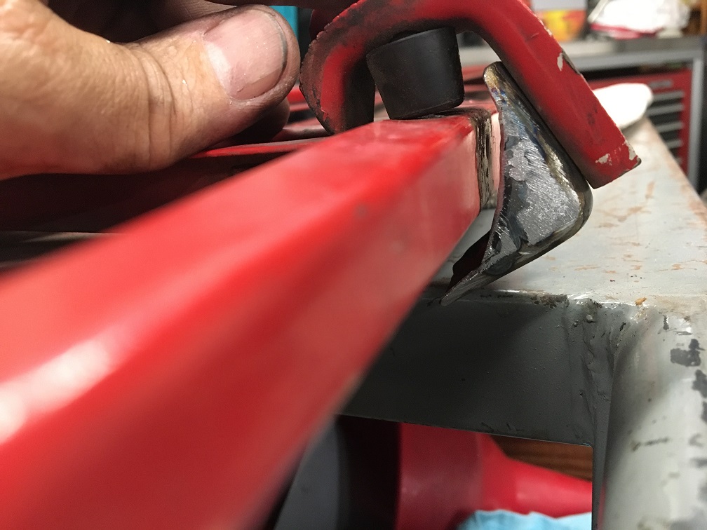 I am pretty sure this is the end of the bracket cracking problem! (IMG:style_emoticons/default/sunglasses.gif) Here the rebuilt bracket is welded to the firewall on the sides catching more of that embossing. Hopefully, this will also prevent problem #2 explained earlier. That being said, all of these issues can probably be avoided by holding the engine lid as it is being released. An easy good habit that many of us have very early on adhered to for obvious reasons. (IMG:style_emoticons/default/smile.gif) 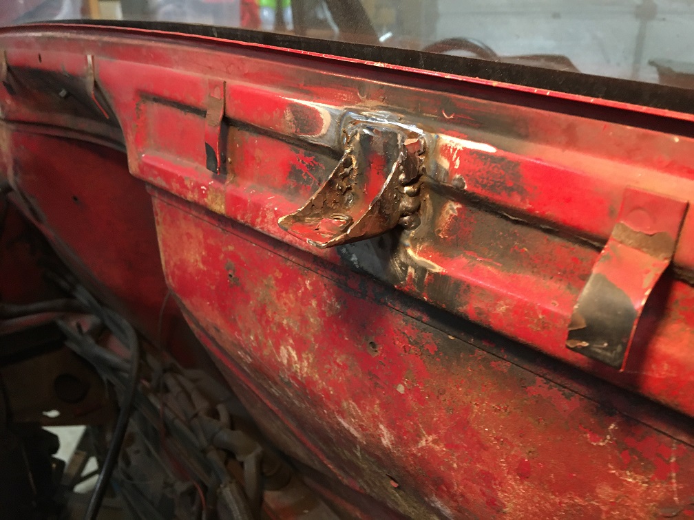 Not shown, but the engine lid was properly aligned to the body in order to set the "L" bracket in the right location on the firewall. |
|
|
|
| Montreal914 |
Dec 12 2021, 01:56 PM
Post
#49
|
|
Advanced Member Group: Members Posts: 2,112 Joined: 8-August 10 From: Claremont, CA Member No.: 12,023 Region Association: Southern California |
Wow it has been many months since I have updated this thread. (IMG:style_emoticons/default/sad.gif) The good news it that I did make progress! (IMG:style_emoticons/default/smile.gif)
Planning ahead, I am doing modifications to the oil network. Although this is a 4 cylinder car, I intend to stroke my current 2056 to a 2258 (2270) in the future. So I already have made changes on the engine side as described in this halted (for this body work) Microsquirt thread: Post #46 here: http://www.914world.com/bbs2/index.php?sho...42361&st=40 I made an aluminum panel for the remote oil filter and thermostat. I will be using a rabbit/jetta diesel filter which is rather large (almost 1 quart). 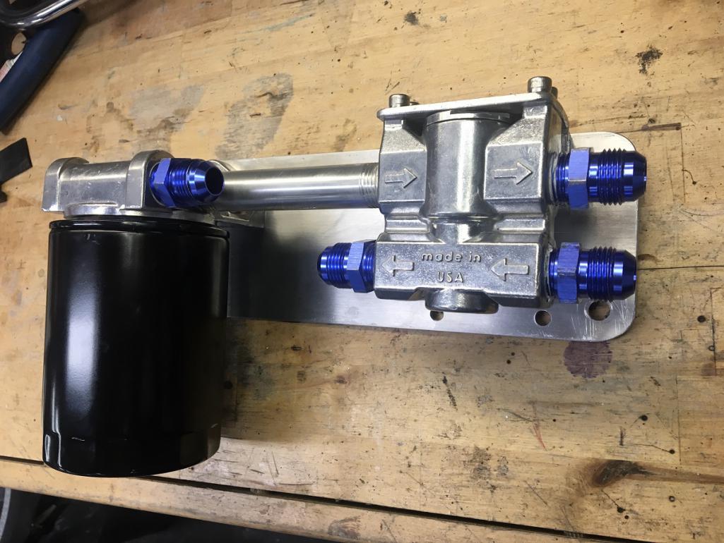 I welded 4 cylindrical tapped standoffs (911 part) to the lower right portion of the firewall to mount the assembly. The filter is high enough to be fully protected. The oil lines from and to the engine will connect in the middle area of the assembly, while the lines to the front cooler connect to the right side of the thermostat. This also clears the heating flexible tube between the heater valve and body heater duct. 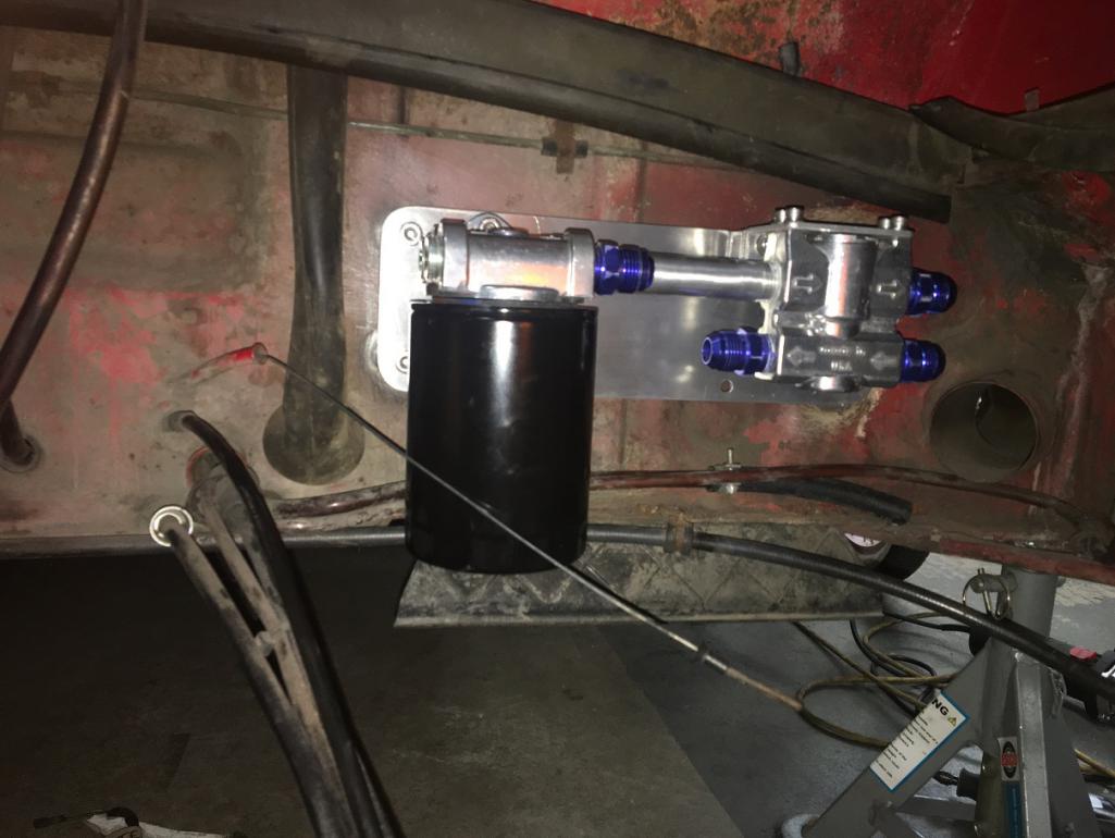 More to come... (IMG:style_emoticons/default/stirthepot.gif) |
|
|
|
| Montreal914 |
Dec 12 2021, 06:18 PM
Post
#50
|
|
Advanced Member Group: Members Posts: 2,112 Joined: 8-August 10 From: Claremont, CA Member No.: 12,023 Region Association: Southern California |
Between the filter/thermostat assembly and the front cooler, I plan on routing the lines along the outside of the passenger long. About 10 years ago, I fitted the car with a Brad Mayer reinforcement kit which actually butts in on the back side of the tapered box in the front of the long. Since it sits away from the outer long of about 3/8", it is obstructing some of the box' backside preventing me from drilling holes large enough to run the lines through the box à la Elephant racing hard lines. Therefore I had to create a channel in the box to make room for the lines.
Here is the box with the reinforcement kit butting on its back side: 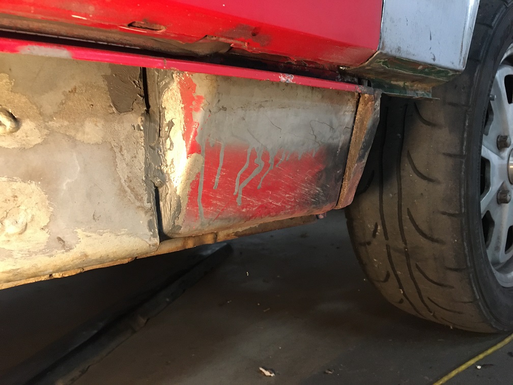 Now the box has been opened up with the removal of the lower front corner that was rusted: 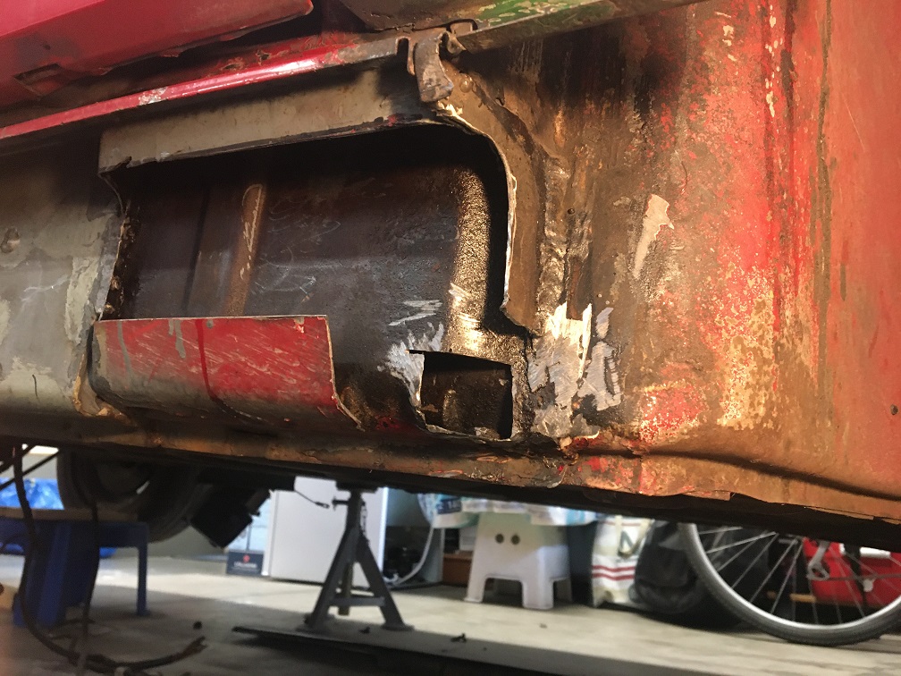 Patching the corner: 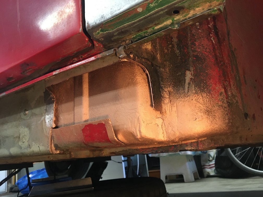 And now putting back the lower front part of the box leaving a trench for the lines to go through: 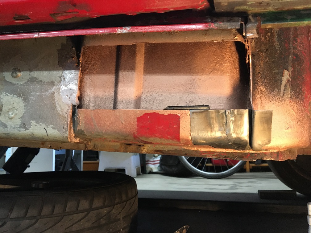 Finally, after shaping the trench from a flat sheet, I closed up the box to keep some structure integrity. Shown here with my line mockup: 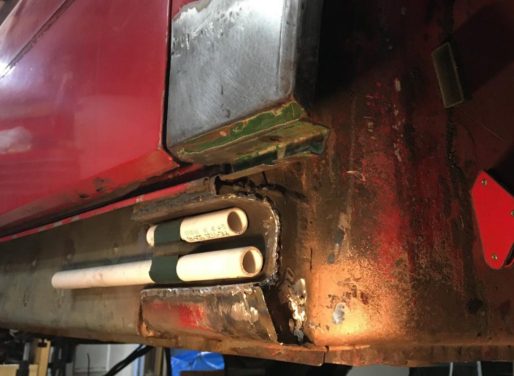 Next, the jack point pyramid had to be trimmed for the same purpose. This pyramid is part of Brad Mayer's kit and is made of thick steel: 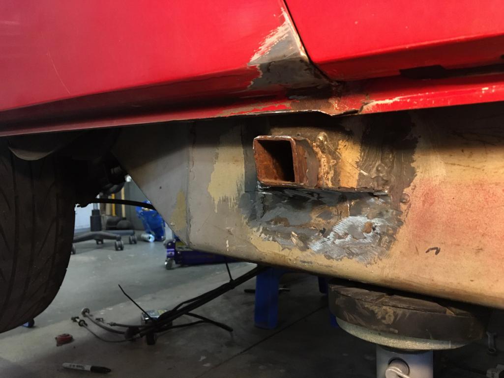 At this point the path is clear to run the oil lines along the passenger side longitudinal beam. (IMG:style_emoticons/default/smile.gif) |
|
|
|
| Montreal914 |
Dec 12 2021, 07:19 PM
Post
#51
|
|
Advanced Member Group: Members Posts: 2,112 Joined: 8-August 10 From: Claremont, CA Member No.: 12,023 Region Association: Southern California |
Although I could have elected to use steel braded lines or rubber hoses, I really like the idea of having rigid oil lines. Being on a tight budget, I studies my options and decided to use aluminum 5052-0, 3/4" x 0.049" tube from Aircraft Spruce. These come in 6 foot length and cost $39 ea. They also sell the -12 AN flared tube sleeve and nuts for them at very reasonable price (~4$ ea). Total material cost ~$105! (IMG:style_emoticons/default/sunglasses.gif)
Since I am not in business of bending tube, I got a cheap 3/4" tube bender on ebay for $38 and was ready to get crafty. (IMG:style_emoticons/default/smash.gif) After very carefully studying the path I wanted to take, I started bending, knowing there wasn't any room for error since I was going to need the entire 6 feet to go from the back to the front. First bend: 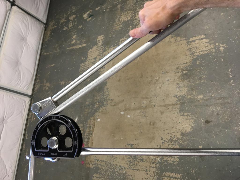 Without being perfect, I was actually pleased with the result that this $38 toll was giving: 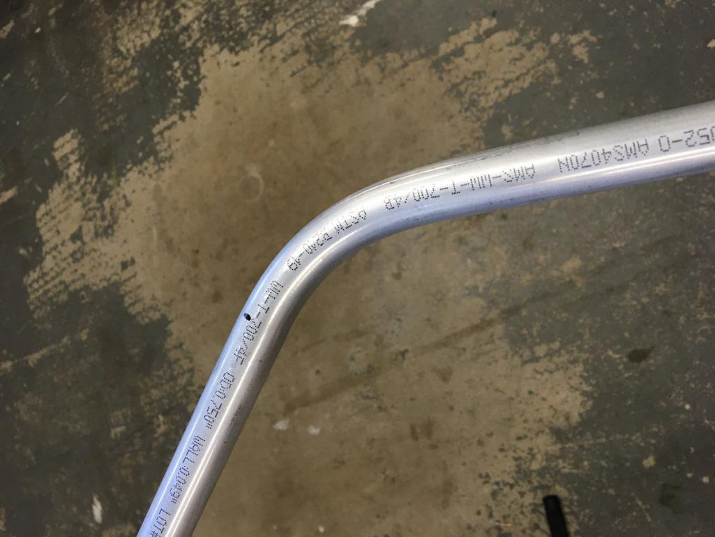 After a few hours of trial fit and bending, I was making encouraging progress. The thickness of the Brad Mayer panels allowed me to drill and tap M6 holes to mount the Abel style SS clamps (Amazon $11): 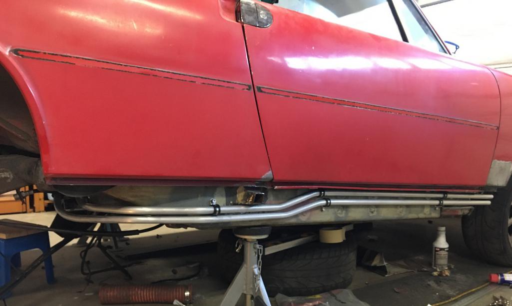 Details of the back end: 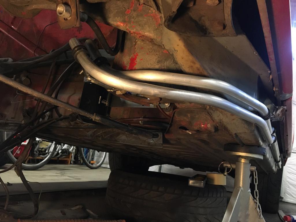 Then I fabricated a rear support that will use one of the two engine mount bracket bolt: 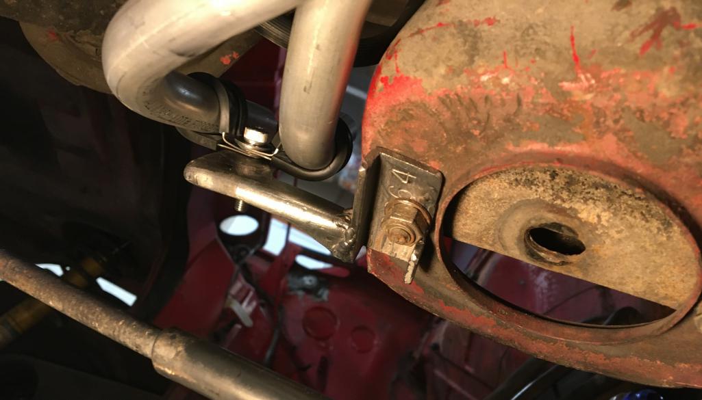 The last few steps were to complete the ends. This mean trimming the length on the back end and bending the front end upwards in the fender well. Last, obviously install the AN fittings and flare the end of the lines. For this I was fortunate enough to borrow a 37degree flaring tool from a friend. Result once flared: 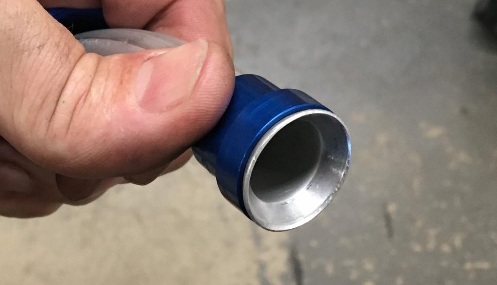 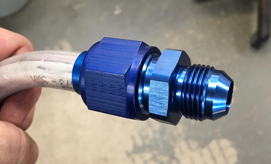 And the final pre-installation with fitting and mounts. I plan on fabricating a front support to hold the lines at the junction with the flexible lines. The front mount should serve two purpose: supporting the end of the rigid lines and being an anchor point for a partial fender liner to protect the lines from flying road debris. 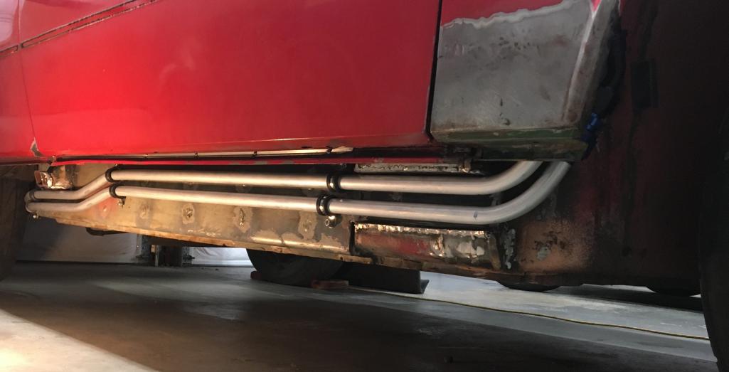 Inner fender area: 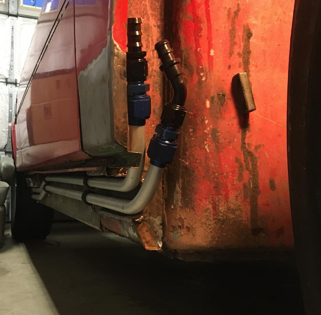 And finally, the back end with the mockup connection to the filter/thermostat assembly: 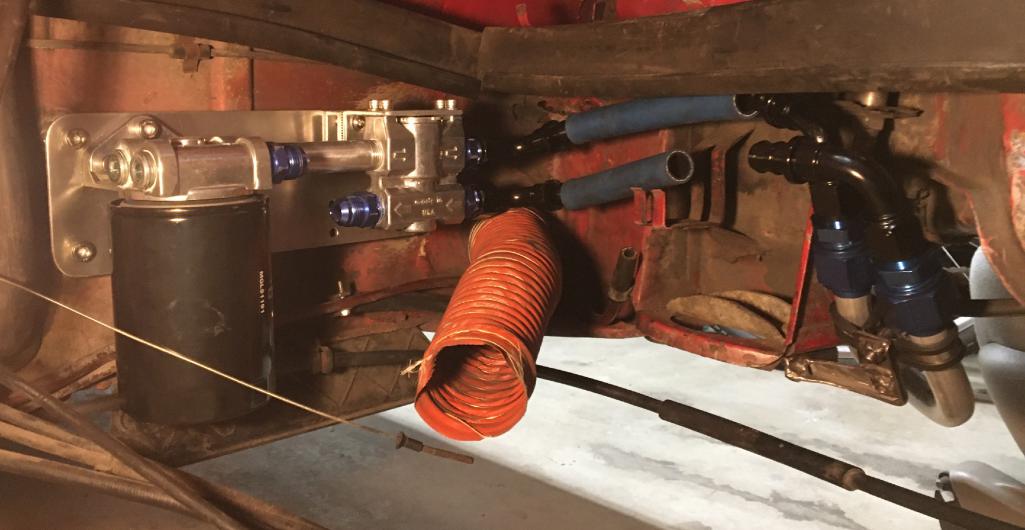 And there you have it! My $115 rigid oil lines! (IMG:style_emoticons/default/sunglasses.gif) |
|
|
|
| Montreal914 |
Dec 12 2021, 07:45 PM
Post
#52
|
|
Advanced Member Group: Members Posts: 2,112 Joined: 8-August 10 From: Claremont, CA Member No.: 12,023 Region Association: Southern California |
Now, that the rigid part has been completed, it is time to look into how we will get to the front oil cooler. Connecting to the rigid lines, I am using -10AN Parker push-lock hose.
After locating the right spot to make the openings in the body, I used a knock-out tool I got for $35 on Craigslist. This makes this task a breeze. (IMG:style_emoticons/default/smile.gif) This a picture of the upper left trunk area near the lid hinge (removed) and windshield washer bottle area. 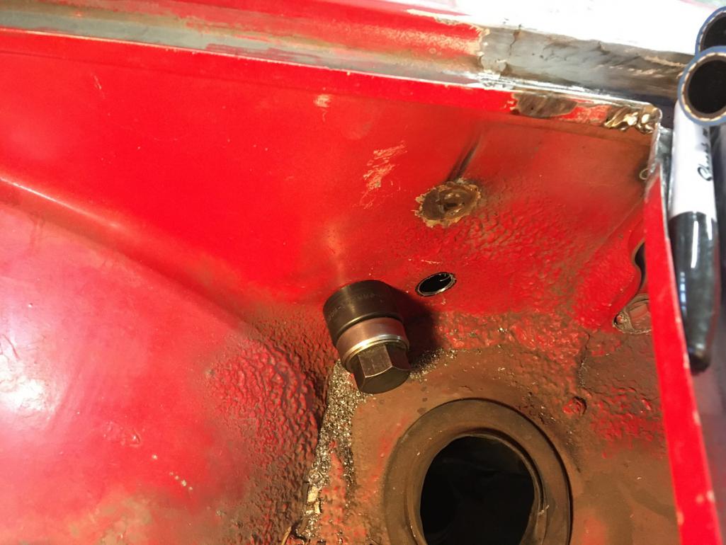 And now with the grommets: 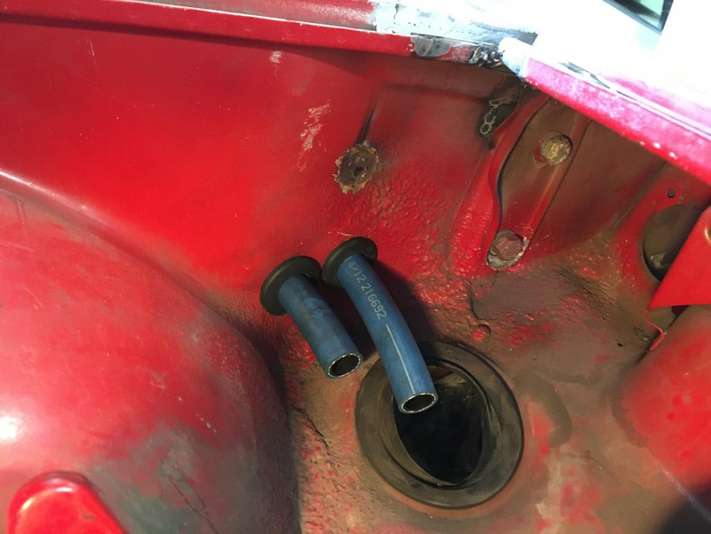 The next openings are through the lower part of the partition wall between the trunk and the fuel tank area. This being a little tighter area, I had to get the lines closer and overlap the holes. We are looking at the rear bottom left area of the front trunk. Next to the paired holes is the air pressure line from the spare to the washer bottle. 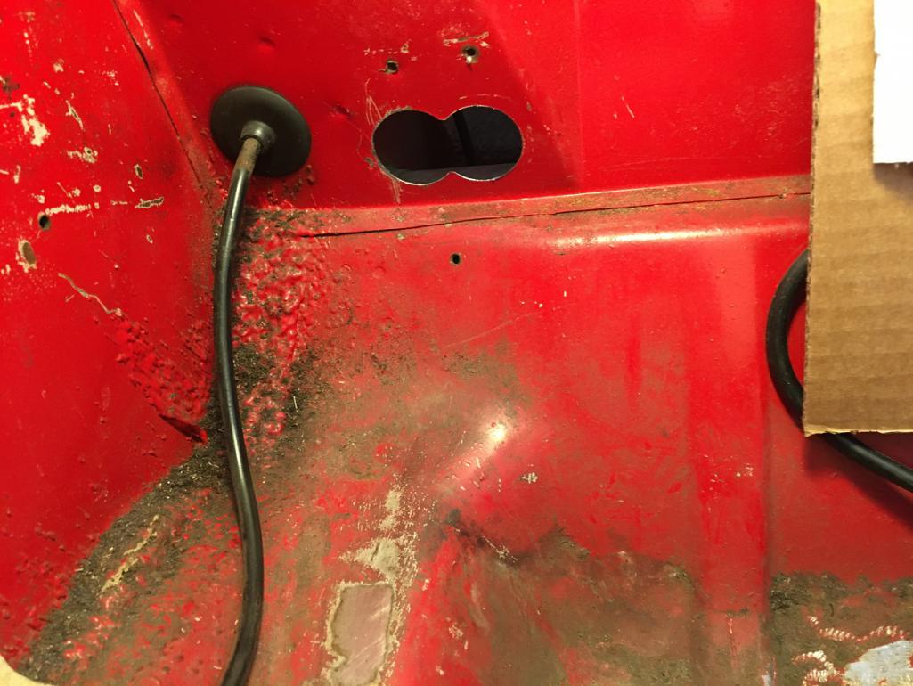 And finally, with trimmed grommets and mock up hoses (out of focus picture but you get the idea... (IMG:style_emoticons/default/biggrin.gif) : 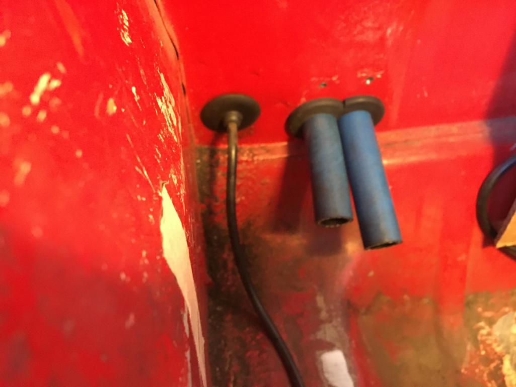 So the final result looks like this in the fender well: 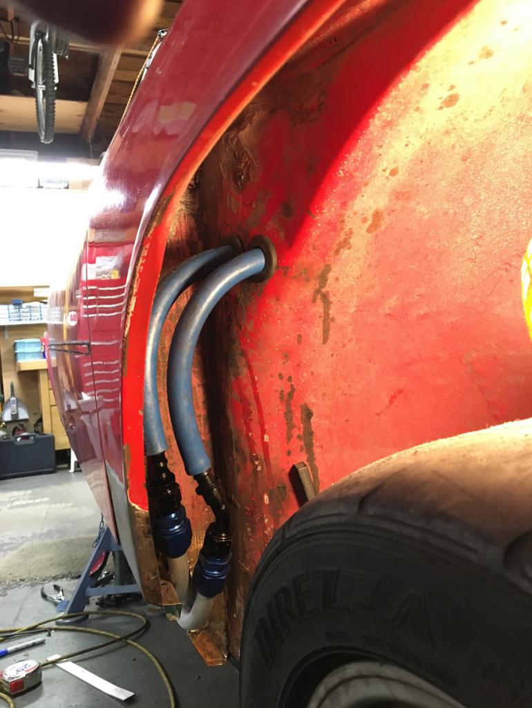 And in the trunk area: 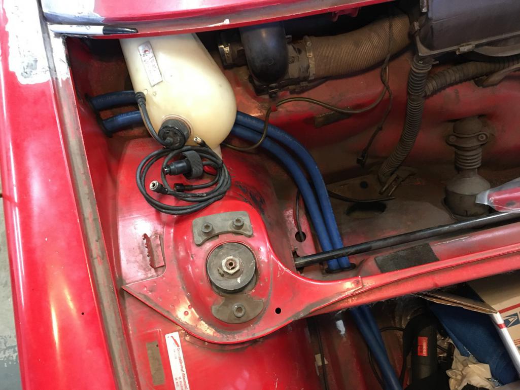 Upcoming next, the front oil cooler! (IMG:style_emoticons/default/smile.gif) |
|
|
|
| bkrantz |
Dec 12 2021, 08:05 PM
Post
#53
|
|
914 Guru Group: Members Posts: 8,710 Joined: 3-August 19 From: SW Colorado Member No.: 23,343 Region Association: Rocky Mountains |
Nice work--looks great!
|
|
|
|
| Montreal914 |
Dec 12 2021, 08:08 PM
Post
#54
|
|
Advanced Member Group: Members Posts: 2,112 Joined: 8-August 10 From: Claremont, CA Member No.: 12,023 Region Association: Southern California |
I am using a Mercedes Diesel oil cooler I got from Bruce Stone a few years ago. There are at least 2 versions of their coolers that are normally mounted vertically to the driver side of the main radiator.
The one I will be using is the smaller one. The main reason is that I wanted it to fit under the arched structural shelf in the front of the car. The cooler came with the mating fittings which makes it convenient. Using my trusted cheapo hack saw, file and vise, I fabricated a couple of brackets out of a 2"x2"x1/8" aluminum square tube. The result is this: 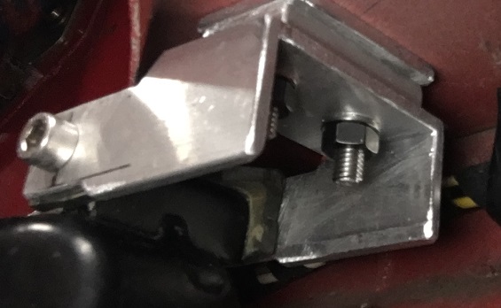 The brackets actually use the stock MBZ cooler mounting points. So the cooler gets attached to the front shelf, suspended from it. The only modifications made to the car at this point are four 1/4" holes in the shelf and the removal of the front rubber plugs. Noting that will weaken the front of the car. Using a torch, I gently heated up the driver side cooler fitting to change its angle to get a smooth path for the blue hose (mock up with black hose here). Also, since the car will be converted to 5 lugs, I am using a 4 1/2" wide Fake Fuch wheel with a small donut spare. The smaller diameter allows me to push the spare against the back end of the trunk while using the stock spare anchoring point but in one of the lug hole instead of the center of the wheel. This creates enough room for the air to exit from the back side of the cooler. Venting will be achieved through the round access ports in the back of the trunk floor. Finally, a new lower trunk floor will close tight and create the plenum for the air flow. Result: Larger trunk space, inflated spare tire, and obviously an oil cooler. (IMG:style_emoticons/default/smile.gif) 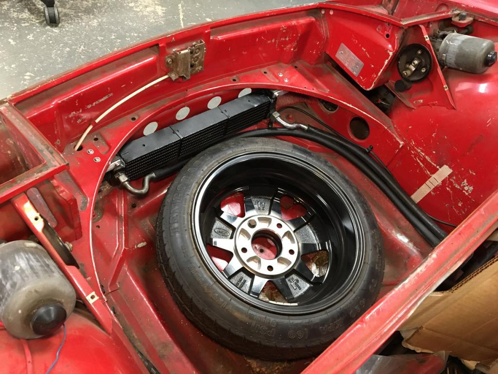 |
|
|
|
| pete-stevers |
Dec 12 2021, 10:09 PM
Post
#55
|
|
Shinee Side Up Group: Members Posts: 2,674 Joined: 10-October 04 From: Abbotsford,BC, Canada Member No.: 2,914 Region Association: Pacific Northwest |
Inspiring thread! that is a job well done! (IMG:style_emoticons/default/biggrin.gif)
|
|
|
|
| Montreal914 |
Dec 12 2021, 11:33 PM
Post
#56
|
|
Advanced Member Group: Members Posts: 2,112 Joined: 8-August 10 From: Claremont, CA Member No.: 12,023 Region Association: Southern California |
QUOTE(pete-stevers @ Dec 12 2021, 08:09 PM) Thank you! I get my inspiration from this forum! (IMG:style_emoticons/default/first.gif) In a way, sharing the progress is motivating. Anyone who has been down this road knows that motivation can have its ups and down. I try to apply the wisdom a good friend once told me: "A little every day!", but it is not easy... Progress and knowing others here are in the same boat is definitely encouraging! (IMG:style_emoticons/default/smile.gif) |
|
|
|
| Cairo94507 |
Dec 13 2021, 08:14 AM
Post
#57
|
|
Michael Group: Members Posts: 10,640 Joined: 1-November 08 From: Auburn, CA Member No.: 9,712 Region Association: Northern California |
Very nicely done. That should keep your engine nice and cool. I really like the hard lines you made - great work. (IMG:style_emoticons/default/beerchug.gif)
|
 |
|
| Montreal914 |
Dec 15 2021, 11:36 AM
Post
#58
|
|
Advanced Member Group: Members Posts: 2,112 Joined: 8-August 10 From: Claremont, CA Member No.: 12,023 Region Association: Southern California |
Here I will need the input from the experienced people! (IMG:style_emoticons/default/smilie_pokal.gif)
My car has been hit in the rear driver side quarter at some point and this translated into an irregular curvature. Recently, I removed the bondo that was causing most of the hump, but as you can see in the pictures below, this was a half way straightening job of the fender. 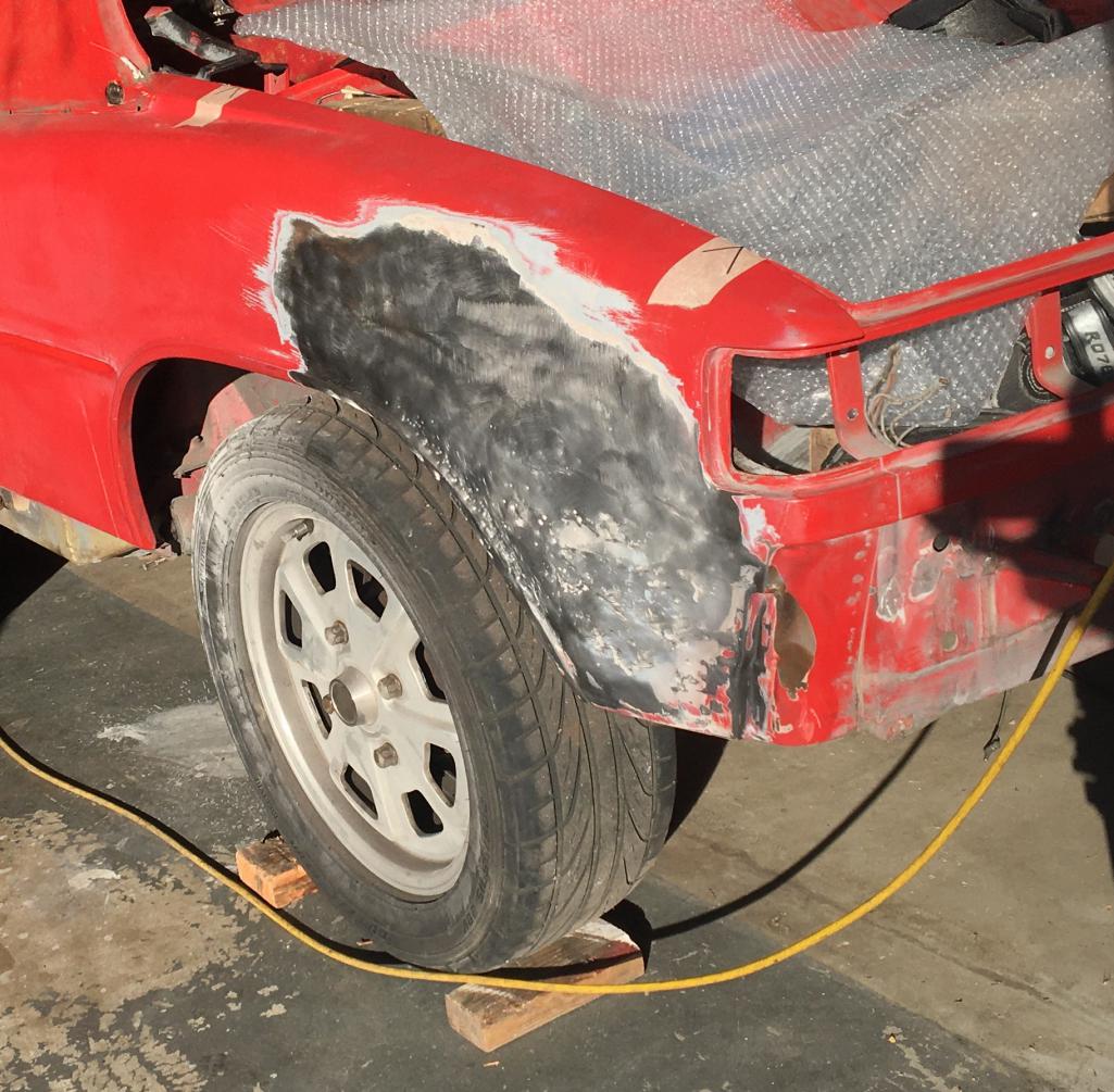 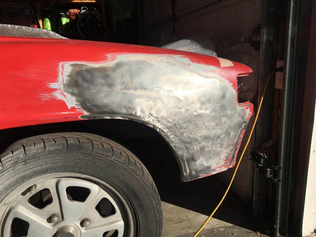 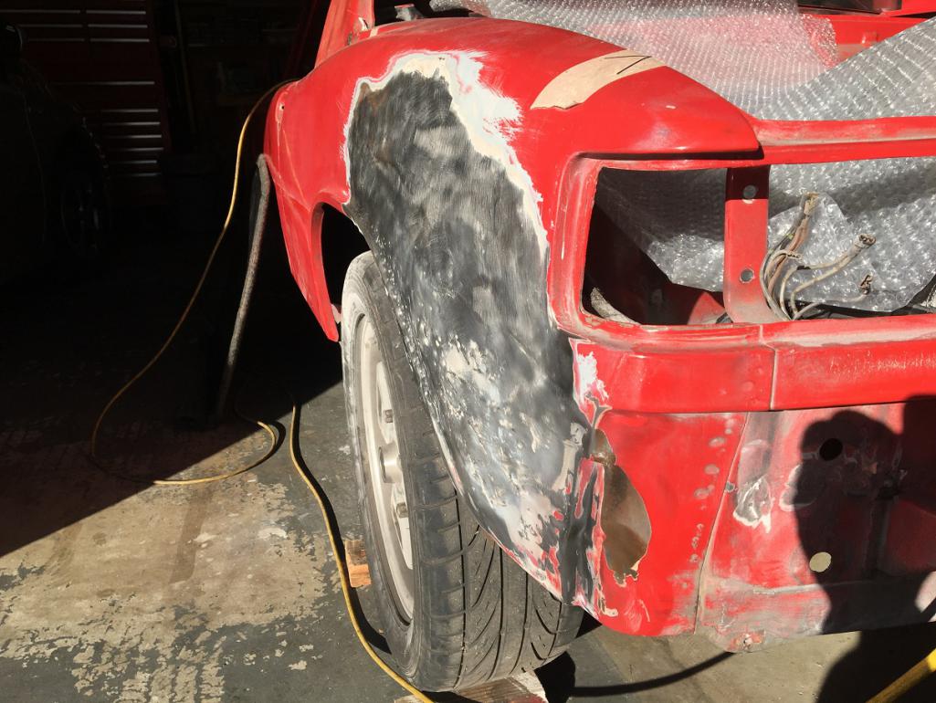 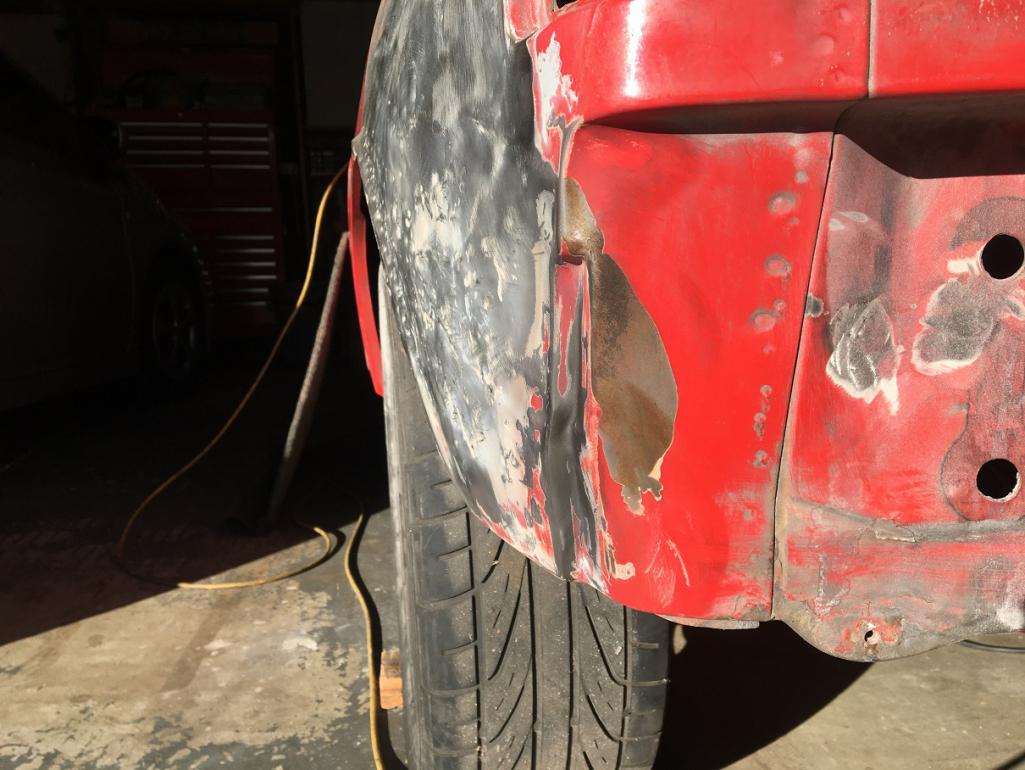 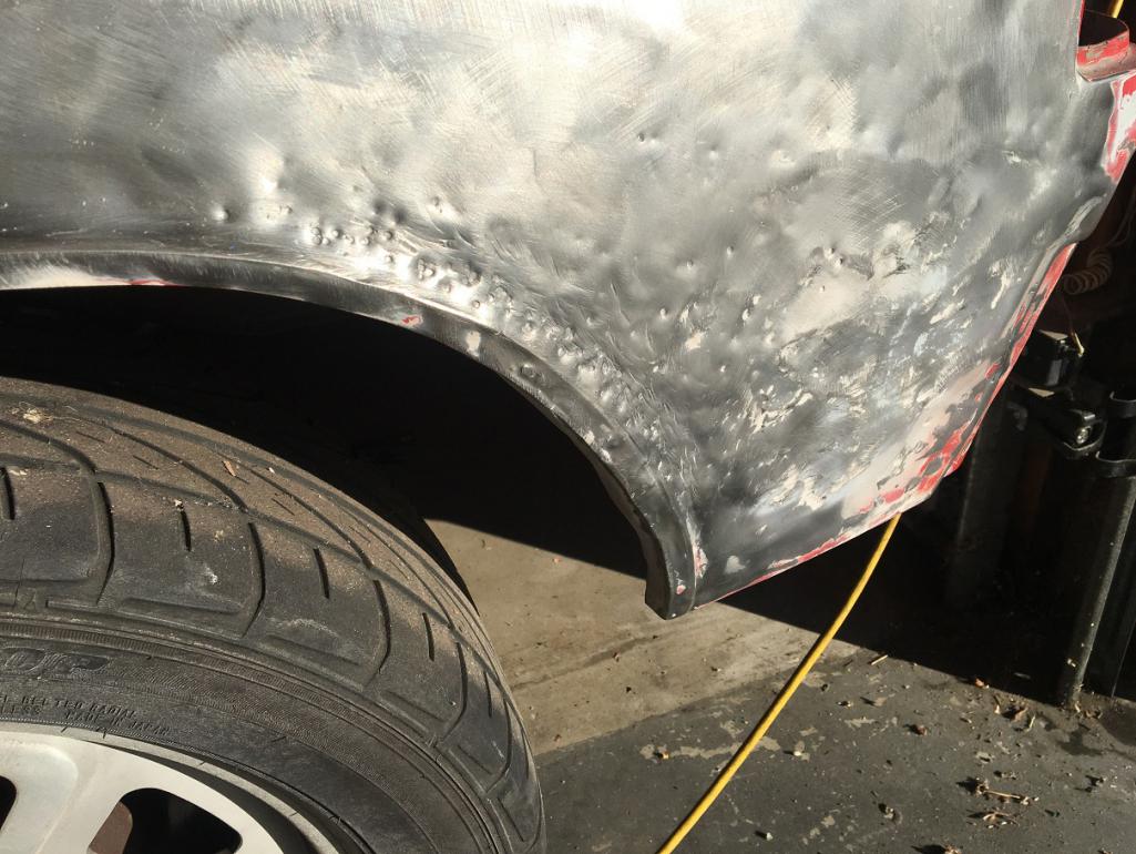 I am pretty sure this fender can be saved by the right qualified person (which is not me) but I fear the cost might be more than cutting and replacing, which is something I can do up to the level of work seen throughout this thread. (IMG:style_emoticons/default/dry.gif) This is not a show car, it will continue being a regularly driven car with a fresh paint. I do have a donner quarter I got from Bruce Stone. Unfortunately, it was cut a little shy on the back side but is probably manageable. Another option would be to get a whole fender from Vince and replace it but that involves dealing with the door, vent area, and sail. 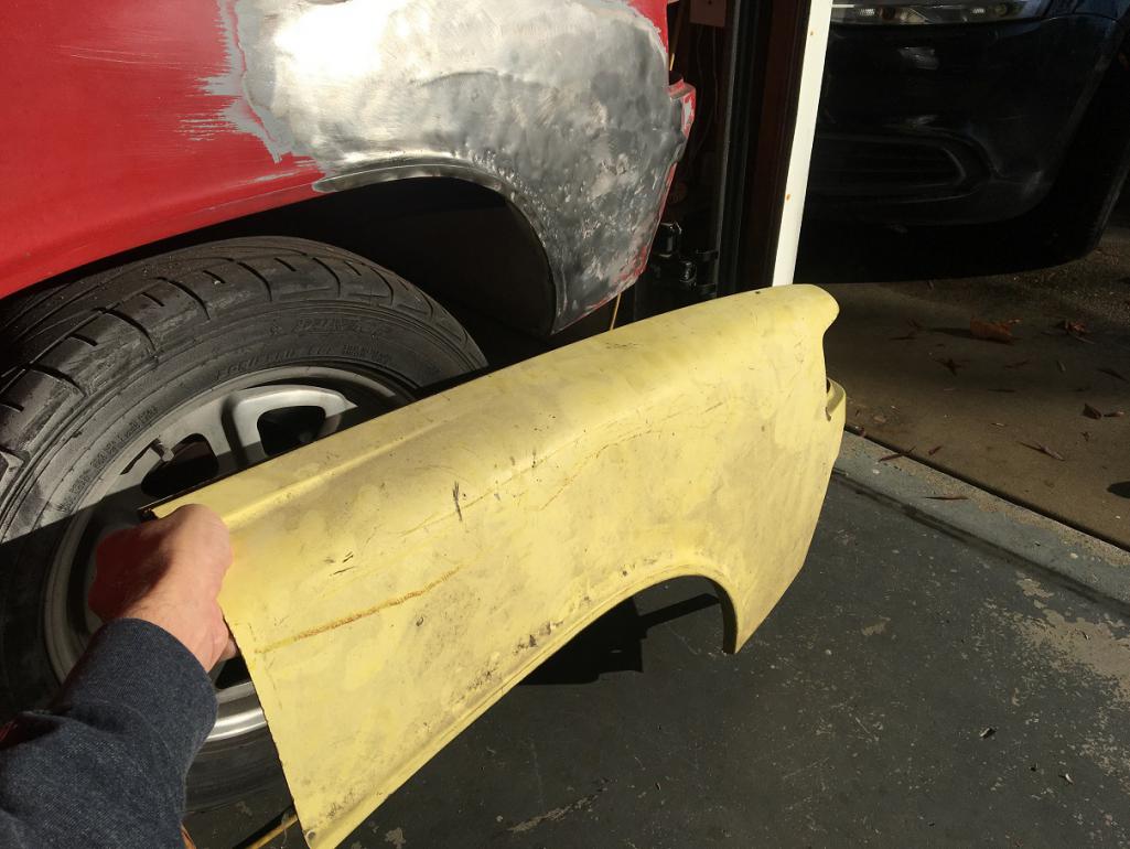 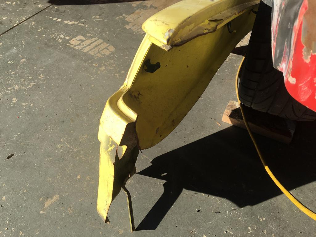 So, should I get this fixed or should I cut and replace? If I do cut/replace, should I replace the whole fender to prevent the vertical scar in the middle? Thank you for the inputs! (IMG:style_emoticons/default/smile.gif) |
|
|
|
| Luke M |
Dec 15 2021, 02:34 PM
Post
#59
|
|
Senior Member Group: Members Posts: 1,521 Joined: 8-February 05 From: WNY Member No.: 3,574 Region Association: North East States |
I've done both of these type of repairs. My brothers 914 did just that, section the rear q-panel. It was kinda of a pain to line things up just right. Took several tries but we did eventually get there. You can see where I cut and butt welded the panels together. Then cut for the flares. Getting the panels to mate just right is hard and it still doesn't look right. Bondo either way we look at it is gonna be the fix now. On my 6, I replaced the whole q-panel. It wasn't that much more work to do. Getting the panel off was the easy part. I cut off the panel then went back and removed the rest of the spot welds. Cut carefully in the targa area as you will cut into the inner support if you go too deep. If you can get your hands on a clean, rust free q-panel just replace it. Have you looked at your targa/door handle area yet? Mine looked great except it was filled with bondo over rust.
Attached image(s) 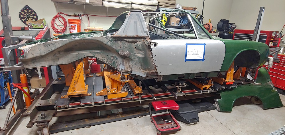 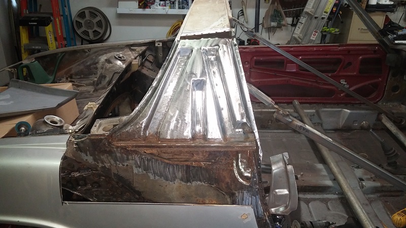 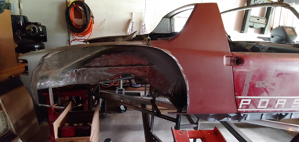
|
|
|
|
| Montreal914 |
Dec 15 2021, 03:27 PM
Post
#60
|
|
Advanced Member Group: Members Posts: 2,112 Joined: 8-August 10 From: Claremont, CA Member No.: 12,023 Region Association: Southern California |
Thank you for the advice and pictures Luke. (IMG:style_emoticons/default/smile.gif)
My door handle and sail area is in decent shape. My fear of replacing the whole quarter is dealing with the tubular vent in the door jamb and all of door edge alignment. I am sure I can get a good condition quarter that would be cut beyond the mating surfaces. I can clean it up to the mating surface making it a "new" part to install. So, from the three options initially mentioned, the current recommendation is: 1- Replace whole quarter 2- Replace partial quarter 3- Straighten whole panel - not commented |
|
|
|
|
3 User(s) are reading this topic (3 Guests and 0 Anonymous Users)
0 Members:

|
Lo-Fi Version | Time is now: 26th May 2026 - 07:06 AM |
Invision Power Board
v9.1.4 © 2026 IPS, Inc.