|
|
|
Porsche, and the Porsche crest are registered trademarks of Dr. Ing. h.c. F. Porsche AG.
This site is not affiliated with Porsche in any way. Its only purpose is to provide an online forum for car enthusiasts. All other trademarks are property of their respective owners. |
|
|

  |

| bbrock |
 Oct 11 2021, 11:59 AM Oct 11 2021, 11:59 AM
Post
#61
|
|
914 Guru  Group: Members Posts: 5,269 Joined: 17-February 17 From: Montana Member No.: 20,845 Region Association: Rocky Mountains |
QUOTE(JamesM @ Oct 11 2021, 02:21 AM)  With larger injectors you lose some level of precision in fuel metering. I experienced this first hand when a early version of the MS1 code was unable to control the larger injector well enough for a decent idle. I was reading about that last night. It sounded like this has been improved in later code versions. One discussion indicated it becomes a problem with pulse widths of 2 ms. Seems like it would be worth doing some more research. QUOTE At higher duty cycles both batch and sequential are putting the same amount of fuel though the open valve just as a result of how long the injector is firing for, so the only real difference is going to be seen below the point where the sequential starts firing on the closed valve. So when comparing 26lb to 36lb injectors with sequential injection we are basically looking at a trade off between fueling precision across the entire operating range vs possible improvement in the 1500-2200 RPM range due to firing 100% on an open valve, and honestly how much time do you spend driving in that range? I think I would go with the smaller injector either way. If my logic is right, batch firing delivers a charge in two squirts per cycle so a minimum of 50% of the charge will be sprayed onto a closed valve. That suggests some potential benefit up to 2000-3000 rpm depending on injector size because you'd have at least 25% more of the fuel charge spraying into open valves. Batch and sequential wouldn't be fully equivalent until at least 50% of the sequential charge goes on closed valves. Engine speeds up to 3000 rpm covers pretty much all city driving, which has been about a third of the driving I've done in the car so far. Most of that is speeding up or slowing down and there isn't much chance to cruise a 3K rpm. That's exactly where I expect the most potential to improve fuel economy. Looking at my old mileage records for this car when driving on pure leaded gas, I consistently got mid to upper 30s on tanks of pure highway driving (remember it was 55 mph speed limit then) and don't expect much room for improvement there. But I got low to mid teens in town. Pretty horrible for such a small car really. I don't know if it is realistic, but low to mid 20s in town would be nice. QUOTE You really took me seriously on the math there! I cheated when i looked into it and just used recorded duty cycles across the RPM range for my setup from my datalogs, wound up with a similar result though, if I recall in my case the the cutoff was going to be somewhere around 1800rpm which for my purposes wasn't worth the effort/cost. Ha ha. It was a fun little exercise. Glad to hear we came up with similar results. I wasn't sure how reliable this process for calculating would be. |
   |

 
|
| jd74914 |
Oct 11 2021, 12:38 PM
Post
#62
|
|
Its alive Group: Members Posts: 4,881 Joined: 16-February 04 From: CT Member No.: 1,659 Region Association: North East States |
QUOTE(bbrock @ Oct 11 2021, 12:59 PM) QUOTE(JamesM @ Oct 11 2021, 02:21 AM) With larger injectors you lose some level of precision in fuel metering. I experienced this first hand when a early version of the MS1 code was unable to control the larger injector well enough for a decent idle. I was reading about that last night. It sounded like this has been improved in later code versions. One discussion indicated it becomes a problem with pulse widths of 2 ms. Seems like it would be worth doing some more research. I'm not sure this is really a 'code' issue. I would place it more in the loop execution time and hardware drivers. From what I've seen over the last decade or so, it doesn't appear the internal code is getting more efficient, the processers are just getting faster. So with that, best course of action for increased time resolution with MS looks to be going with newer hardware (ie: MS3). At super low pulse widths you end up with this injector latency problem which can also pose some issues. On the 'cheap' injector side you aren't finding too many latency and flow matched sets. You could test that though... |
|
|
|
| bbrock |
Oct 11 2021, 02:08 PM
Post
#63
|
|
914 Guru Group: Members Posts: 5,269 Joined: 17-February 17 From: Montana Member No.: 20,845 Region Association: Rocky Mountains |
QUOTE(jd74914 @ Oct 11 2021, 12:38 PM) I'm not sure this is really a 'code' issue. I would place it more in the loop execution time and hardware drivers. From what I've seen over the last decade or so, it doesn't appear the internal code is getting more efficient, the processers are just getting faster. So with that, best course of action for increased time resolution with MS looks to be going with newer hardware (ie: MS3). At super low pulse widths you end up with this injector latency problem which can also pose some issues. On the 'cheap' injector side you aren't finding too many latency and flow matched sets. You could test that though... Good info and that makes sense. I'm wondering if going sequential helps with this problem. Since each injector squirts only once per cycle rather than twice as in batch injection, the pulse widths are double for a give fuel demand. Would that not help with problems of low resolution for large injectors at low speeds? Looking at my tables, it looks like the 36 lbs/hr injector would still have a pulse width of 9.6 ms at idle which doesn't seem too small. |
|
|
|
| jd74914 |
Oct 11 2021, 03:00 PM
Post
#64
|
|
Its alive Group: Members Posts: 4,881 Joined: 16-February 04 From: CT Member No.: 1,659 Region Association: North East States |
Pulses of ~10 ms aren't too bad.
But... I don't see where you add an engine pumping efficiency (VE) into the air flow calculation. I didn't check your calcs from a PV=nRT sense so I'm assuming those are correct in terms of air/fuel mass flows with perfect cylinder filling. The engine is only going to be pumping maybe 10-30%* 'efficiently' at idle making your actual fuel flow requirements much less. Pulses of 0.96 ms are too short. Most injectors have 1-1.5 ms latency (voltage and fuel pressure dependent). *Edit: Found a post showing Falcor76 has ~20% VE @ idle so I think these numbers are somewhat reasonable. |
|
|
|
| Frank S |
Oct 11 2021, 03:49 PM
Post
#65
|
|
Member Group: Members Posts: 135 Joined: 15-April 15 From: Wiesbaden, Germany Member No.: 18,632 Region Association: Germany |
Fuel Injector Size:
https://thedubshop.com/pages.php?pageid=44 I'm running 21lb/hr and they are fine for a 120 HP Engine. Don't go to large as this will be generate problems at idle and in overun conditions with to low pulswidth (out of the linear range of the injectors). MS3 can deal much better with small puls width as the Dead Time Voltage Corretcion is not linear and MS3 is addressing that problem (which alone is a clear advantage if you compare with MS2 or Mircrosquirt). Again Crank and/or Cam sensors: A Crank sensor alone can only be good for Batch injection and Wasted Spark ignition. Why? Because a engine cycle is 720° Crank rotation, so the ECU does not know if the engine is at #1 or #3 TDC. If you add a single tooth Cam Sensor in addition the ECU will be enabled to define #1 TDC, so you could run sequential fuel and spark. If you run a Toothed Wheel Cam/Distibutor Sensor, this sensor allone will enable the ECU to define #1 TDC. This is because 720° Crank rotation = 360° Cam/Distributor rotation. Sequential Modification: You don't need to modify the MS2V3 board for sequential Fuel and Spark if you use the MS3. The MS3 daughtercard has all the outputs available, you just need to connect them to the JPB Board you are planning to use. |
|
|
|
| bbrock |
Oct 11 2021, 04:04 PM
Post
#66
|
|
914 Guru Group: Members Posts: 5,269 Joined: 17-February 17 From: Montana Member No.: 20,845 Region Association: Rocky Mountains |
QUOTE(jd74914 @ Oct 11 2021, 03:00 PM) Pulses of ~10 ms aren't too bad. But... I don't see where you add an engine pumping efficiency (VE) into the air flow calculation. I didn't check your calcs from a PV=nRT sense so I'm assuming those are correct in terms of air/fuel mass flows with perfect cylinder filling. The engine is only going to be pumping maybe 10-30%* 'efficiently' at idle making your actual fuel flow requirements much less. Pulses of 0.96 ms are too short. Most injectors have 1-1.5 ms latency (voltage and fuel pressure dependent). *Edit: Found a post showing Falcor76 has ~20% VE @ idle so I think these numbers are somewhat reasonable. Excellent! Yes, there's a little obscure note in the chart that says VE is calculated at 100%. This is all new to me so I was going to refine the values to include more realistic VE numbers later. Any guidance on some standard VE values to plug in? So far I've only found typical values at max HP. This is obviously critical to the analysis. So assuming 10% VE, the idle pulse width should be around 1.3 ms with 26 lb injectors and, as you said, 0.96 ms with 36 lb. That puts the nail in the coffin for the larger injectors it seems. It seems even the 26 lb injectors might be pushing the limit. Assuming 20% VE at idle, I get a 2.7 ms pulse width with the 26s (1.9 ms with 36s). Playing with VE a little and assuming a static 85% through the range above idle stretches out the theoretic band where sequential could potentially benefit. I've added curves for % of charge sprayed into open valves below with a reference line at 50% to show the point where sequential is no different from batch. Once I have more realistic guestimate numbers for VE, I'll post updated tables. 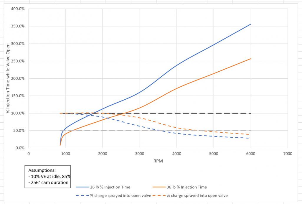 |
|
|
|
| crash914 |
Oct 11 2021, 04:06 PM
Post
#67
|
|
its a mystery to me Group: Members Posts: 1,830 Joined: 17-March 03 From: Marriottsville, MD Member No.: 434 Region Association: MidAtlantic Region |
Call Mario.
Ask about the MAX EFI. will integrate O2 sensor, cam sync, CNP, full sequential. It works well. |
|
|
|
| bbrock |
Oct 11 2021, 07:24 PM
Post
#68
|
|
914 Guru Group: Members Posts: 5,269 Joined: 17-February 17 From: Montana Member No.: 20,845 Region Association: Rocky Mountains |
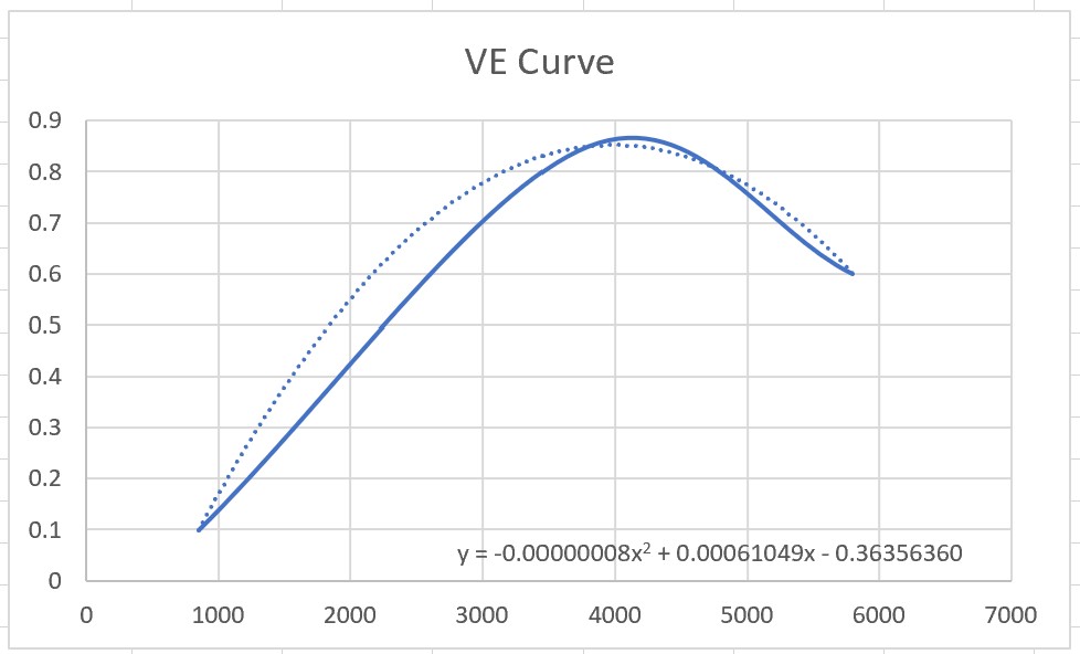
Well no reason to stop this insanity now, so here's more fun with math. I found a good discussion about VE vs engine speed for a stock 2.0L on Pelican. It didn't provide a nice table of VEs I would have liked, but led to enough info to make some WAGs to get closer with my chicken scratch estimates. I learned that VE typically follows the torque curve with peak VE being at about the same engine speed as peak torque. I also learned that typical peak VE values for 4 cylinder, 2 valve, overhead cam engines is 75-80% So I plotted a graph using 10% VE at idle to represent worst case in terms of small pulse width and max of 80% at about 3800 rpm which looks about where the 2.0L peaks (I was too lazy to look up the actual peak), and I dropped it to 60% @ 5800 rpm - again, just trying to match the shape of the torque curve. Then I had Excel calculate a polynomial equation for the shape and used that to plug in VE values in my tables. Whew - we're into some nerd shit now!
 The results are interesting. 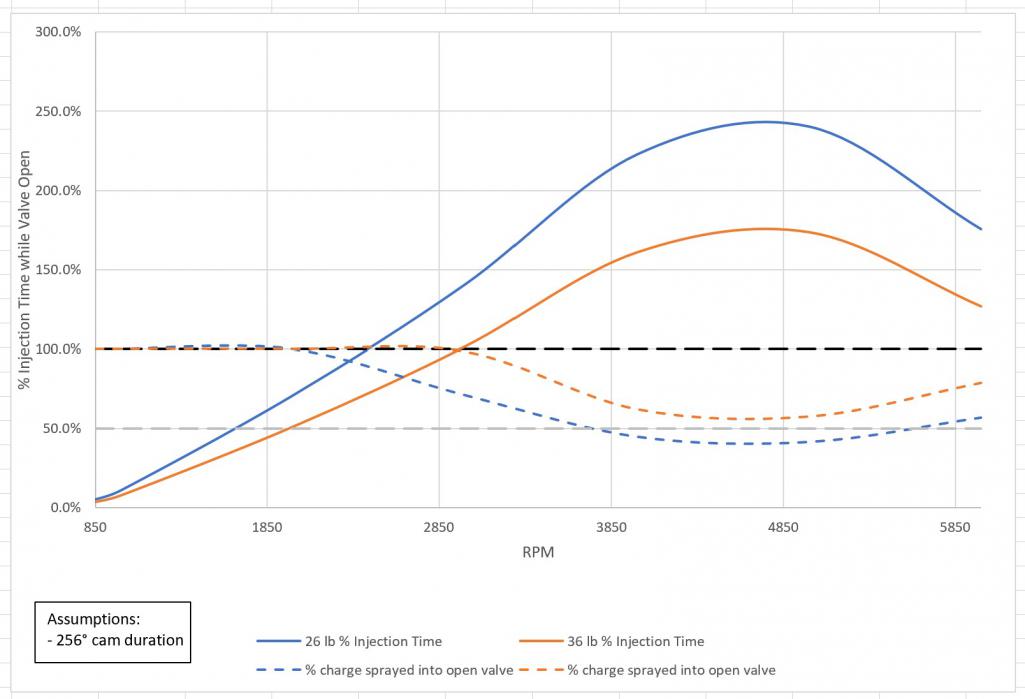 With this adjustment, both injectors extend the range where sequential would spray more of the charge into open valves than batch. Really intriguing is that the 36 lb injectors would still be spraying all or nearly all of the charge into open valves into the low 3ks which would be potential efficiency gains even into highway cruising speeds. In fact, the 36 lb never dips below 50% of charge going into open valves. But... there is still that pesky 0.94 ms pulse width @ idle. It would be nice to know what that minimum VE would actually be because even at 20% VE, the minimum pulse width climbs to 1.9 ms which might just be doable with MS3. 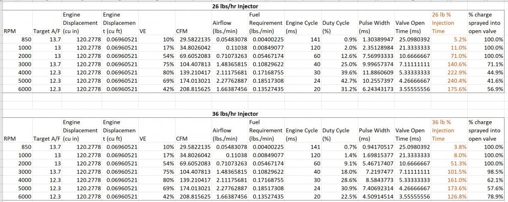 |
|
|
|
| bbrock |
Oct 11 2021, 07:45 PM
Post
#69
|
|
914 Guru Group: Members Posts: 5,269 Joined: 17-February 17 From: Montana Member No.: 20,845 Region Association: Rocky Mountains |
QUOTE(Frank S @ Oct 11 2021, 03:49 PM) Fuel Injector Size: https://thedubshop.com/pages.php?pageid=44 I'm running 21lb/hr and they are fine for a 120 HP Engine. Don't go to large as this will be generate problems at idle and in overun conditions with to low pulswidth (out of the linear range of the injectors). MS3 can deal much better with small puls width as the Dead Time Voltage Corretcion is not linear and MS3 is addressing that problem (which alone is a clear advantage if you compare with MS2 or Mircrosquirt). I think I need to look a little more into MS3 or maybe the MAX EFI option @crash914 mentioned to see if they would let me run a smaller pulse width. MS3 would add about $200 to the project ($100 more than MS2 for the board kit plus $100 for the MS3X board to get the sequential output channels. I've looked at Mario's and a couple other injector calculators and they all followed the same equation. Looks to me like they are just sizing the injector to be able to provide enough charge per cycle for the HP to be generated. Makes sense but it looks like squeezing efficiency our of sequential injection really depends on the timing of when the charge is sprayed to get as much as possible into the open valve for better atomization. Hence, the obsession over the larger injectors. QUOTE Again Crank and/or Cam sensors: A Crank sensor alone can only be good for Batch injection and Wasted Spark ignition. Why? Because a engine cycle is 720° Crank rotation, so the ECU does not know if the engine is at #1 or #3 TDC. If you add a single tooth Cam Sensor in addition the ECU will be enabled to define #1 TDC, so you could run sequential fuel and spark. If you run a Toothed Wheel Cam/Distibutor Sensor, this sensor allone will enable the ECU to define #1 TDC. This is because 720° Crank rotation = 360° Cam/Distributor rotation. Good info! QUOTE Sequential Modification: You don't need to modify the MS2V3 board for sequential Fuel and Spark if you use the MS3. The MS3 daughtercard has all the outputs available, you just need to connect them to the JPB Board you are planning to use. I looked into the daughter board and you still have to add the MS3X board to get the sequential output channels. Seems kind of weird MS3 doesn't have at least 4 injector channels built in, but I haven't found anything to indicate otherwise. The MS2 mod is really just removing a few components and adding some jumpers to repurpose unused features as output pins for injectors. If you are building the board from kit, the mod is more just skipping a few steps on assembly. Still, if MS3 can handle short pulse widths, that would be a good reason to use it. |
|
|
|
| Frank S |
Oct 11 2021, 10:55 PM
Post
#70
|
|
Member Group: Members Posts: 135 Joined: 15-April 15 From: Wiesbaden, Germany Member No.: 18,632 Region Association: Germany |
[quote]Sequential Modification:
You don't need to modify the MS2V3 board for sequential Fuel and Spark if you use the MS3. The MS3 daughtercard has all the outputs available, you just need to connect them to the JPB Board you are planning to use. [/quote] I looked into the daughter board and you still have to add the MS3X board to get the sequential output channels. Seems kind of weird MS3 doesn't have at least 4 injector channels built in, but I haven't found anything to indicate otherwise. The MS2 mod is really just removing a few components and adding some jumpers to repurpose unused features as output pins for injectors. If you are building the board from kit, the mod is more just skipping a few steps on assembly. Still, if MS3 can handle short pulse widths, that would be a good reason to use it. [/quote] I wasn't clear about the board. I thought about adding this: http://jbperf.com/quad_ign_inj/index.html Instead of the MS3X board. Regarding your fuelinjector thoughts, you don't want to spray into the open valve. MS3 is providing so much more value over MS2 that it is fully worth the extra $$ and I think if you would talk to the guys at DYI Autotune, they would also sell a MS2 kit without a MS2 daughtercard and adding a MS3 daughtercard therefore, which will remove some cost at least. The MS3 dauthercard will also fit into the MS2 case if you slightly modify it and the MS2 case will also fit into the original D-Jet housing if you want to stay with the original look. |
|
|
|
| JamesM |
Oct 12 2021, 01:17 AM
Post
#71
|
|
Advanced Member Group: Members Posts: 2,269 Joined: 6-April 06 From: Kearns, UT Member No.: 5,834 Region Association: Intermountain Region |
It sounds like you really want to go with the 36lb injectors (IMG:style_emoticons/default/biggrin.gif)
Larger injectors will always have less resolution smaller ones BUT 36lb injectors wont be an issue with an MS2 or newer CPU, it was only MS1 hardware that lacked the resolution under the stock code base to control them properly at idle. If I recall it wasn't so much an issue with the speed of the CPU as it was the limited CPU register capacity which is why they were able to address it with a custom code version that gave up other features in order to gain extra register space. We are talking ancient history here (15 or so years ago when all the MS code was written in assembly) so im not 100% on the specifics, but operationally hasn't been an issue since the early days, I ran the stock 2.0 (36lb) injectors for years, no big deal. That being said, because you do loose some resolution with the larger injectors you will want to be sure all your injection related settings, especially the injector dead time and voltage correction factors are set as exact as possible (something that is impossible with stock injectors) as having the larger injectors amplifies mixture issues due to minor voltage fluctuations. Given that fact along with what you seem to be going for here 'Frank S' brings up a good point about MS3 actually having a full table for injector voltage correction vs the MS2s linear correction. I had completely forgotten about that feature difference but am now reminded that the linear correction was one of the things that slightly annoyed me once I changed over to injectors that actually had documented voltage correction tables with them. Given you shouldn't see more than a 1-2 volt delta under normal operation conditions the linear settings get you pretty damn close (i can kick on my headlights with no AFR change noted) so for me it was splitting hairs, but if you really want to optimize it with the larger injectors, having the full correction table may be the way to go. As for PW at idle, ill have to see if i have any old logs, but if i recall on a stock motor with the large injectors I was sitting somewhere in the low to mid 2ms range. Issue with the original MS1 code though was that it could only control PW in .1ms increments and the AFR difference between a 2.2ms and 2.3 ms injection pulse at idle with a 36lb injector was surprisingly large. Thankfully that is no longer an issue. I know you haven't built your system yet, but based on what i have seen you doing so far I'm going to call it now and say you are going to wind up with the most precise (and thoroughly planned out) MS build to date. (IMG:style_emoticons/default/first.gif) |
|
|
|
| jd74914 |
Oct 12 2021, 07:08 AM
Post
#72
|
|
Its alive Group: Members Posts: 4,881 Joined: 16-February 04 From: CT Member No.: 1,659 Region Association: North East States |
QUOTE(bbrock @ Oct 11 2021, 08:45 PM) QUOTE Again Crank and/or Cam sensors: A Crank sensor alone can only be good for Batch injection and Wasted Spark ignition. Why? Because a engine cycle is 720° Crank rotation, so the ECU does not know if the engine is at #1 or #3 TDC. If you add a single tooth Cam Sensor in addition the ECU will be enabled to define #1 TDC, so you could run sequential fuel and spark. If you run a Toothed Wheel Cam/Distibutor Sensor, this sensor allone will enable the ECU to define #1 TDC. This is because 720° Crank rotation = 360° Cam/Distributor rotation. Good info! I actually have a toothed cam wheel with hall effect trigger somewhere in the garage. Never used it, but let me see if I can dig it out to show how it was done. |
|
|
|
| jd74914 |
Oct 12 2021, 07:18 AM
Post
#73
|
|
Its alive Group: Members Posts: 4,881 Joined: 16-February 04 From: CT Member No.: 1,659 Region Association: North East States |
QUOTE(bbrock @ Oct 11 2021, 08:45 PM) I've looked at Mario's and a couple other injector calculators and they all followed the same equation. Looks to me like they are just sizing the injector to be able to provide enough charge per cycle for the HP to be generated. Makes sense but it looks like squeezing efficiency our of sequential injection really depends on the timing of when the charge is sprayed to get as much as possible into the open valve for better atomization. Hence, the obsession over the larger injectors. What you're seeing is typical of automotive aftermarket...just general equations without much value besides really rough approximations. I'm really enjoying seeing your calculations-thank you! QUOTE(bbrock @ Oct 11 2021, 08:45 PM) I think I need to look a little more into MS3 or maybe the MAX EFI option @crash914 mentioned to see if they would let me run a smaller pulse width. MS3 would add about $200 to the project ($100 more than MS2 for the board kit plus $100 for the MS3X board to get the sequential output channels. Personally, I'd push to an MS3...but its easy to spend other people's money. With an MS2 loop speed of 0.33 ms, assuming engine speed of 3000 rpm, you're looking at the engine moving 5.94 degrees per loop execution time...MS3 @ 0.2 ms gives you 3.6 degrees. Pretty decent difference. Caveat here-I'm not really sure how the code is structured. You would hope they would prioritize some things like injector/ignition switching as well as engine position calculation, but I'm not sure. As a side note, The extreme high end stuff has hardware angle clocks (typ. FPGAs) to keep these kind of calculations off of the main processor. The use the main processor to schedule events to happen at definitely crank angles vs. times. Subtle difference that doesn't really matter for a 50 year old engine, but maybe interesting. QUOTE(JamesM @ Oct 12 2021, 02:17 AM) Given that fact along with what you seem to be going for here 'Frank S' brings up a good point about MS3 actually having a full table for injector voltage correction vs the MS2s linear correction. I had completely forgotten about that feature difference but am now reminded that the linear correction was one of the things that slightly annoyed me once I changed over to injectors that actually had documented voltage correction tables with them. Given you shouldn't see more than a 1-2 volt delta under normal operation conditions the linear settings get you pretty damn close (i can kick on my headlights with no AFR change noted) so for me it was splitting hairs, but if you really want to optimize it with the larger injectors, having the full correction table may be the way to go. (IMG:style_emoticons/default/first.gif) (IMG:style_emoticons/default/agree.gif) I think this correction table is very important. Not a direct comparison, but when tuning high-strung bike motors we found having full voltage correction was exceedingly important. Those were engines with poor charging capability and weight optimized harnesses so voltage drop was a thing. As James said, likely not a huge issue for you but when really pushing it... Now, you've been looking at all of this in terms of fueling during valve opening. This isn't necessarily ideal when you start looking at air/spray flow velocities and mix transit times into the cylinder. The delay is real, particularly due to the variation in intake velocity with crank angle as the valves open. For real optimization you need to tune the injector end angle at all engine speeds and load points... https://www.motec.com.au/forum/viewtopic.php?t=769 I've been fortunate enough to have a load bearing dyno to do sweeps, but this should be doable on the road. Just needs some more logging and drive time. Optimized injection timing minimizes wall condensation and actually can yield some pretty meaningful efficiency gains. You do need good engine position resolution to do this well which really pushes towards the crank sensor (say 36:1 or 60:1 wheel). |
|
|
|
| Superhawk996 |
Oct 12 2021, 08:13 AM
Post
#74
|
|
914 Guru Group: Members Posts: 7,937 Joined: 25-August 18 From: Woods of N. Idaho Member No.: 22,428 Region Association: Galt's Gulch |
You're becoming a real Geek. (IMG:style_emoticons/default/laugh.gif)
I've had these sitting on my shelf since college. I think you need them more than I do. PM me your address and they are on their way to you. 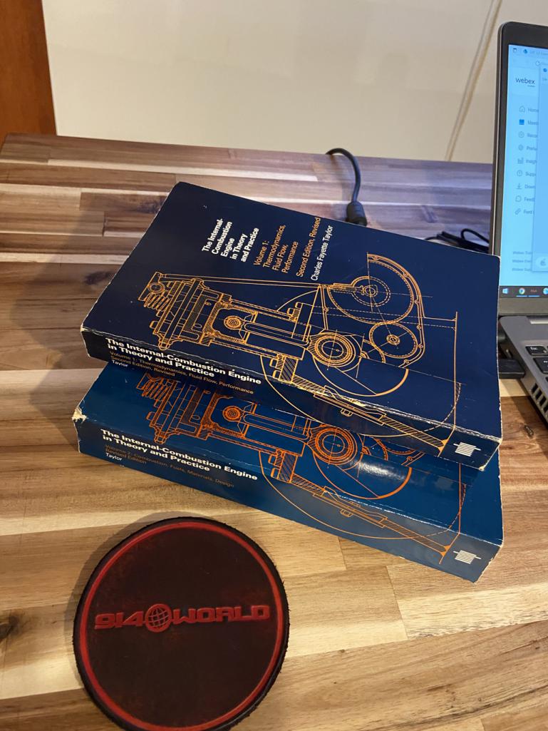 |
|
|
|
| bbrock |
Oct 12 2021, 08:38 AM
Post
#75
|
|
914 Guru Group: Members Posts: 5,269 Joined: 17-February 17 From: Montana Member No.: 20,845 Region Association: Rocky Mountains |
You guys are awesome! (IMG:style_emoticons/default/smilie_pokal.gif)
I was reading through the MS3 tuning manual last night and it does look like MS3 will be worth the added coin. I've officially gone from Microsquirt all the way up to MS3. I'm still a bit confused about cards though and am probably missing something. It looks like the daughter boards are intended to upgrade older boards to newer so an MS2 daughter card is used to upgrade an MS1 to MS2 and MS3 daughter upgrades MS2. Either of these provides only 2 injector channel outputs and the jbperf boards require 4 inputs to drive 4 injectors independently. So it seems you need to modify/expand either MS board to get 4 output channels. Difference being that MS3X can drive high impedence injectors directly where modded MS2 requires a jbperf board. I might be missing something though. @jd74914 you and @Frank S anticipated my next question. I knew talking about spraying into open valves was likely incorrect but was using it as shorthand for getting the most complete atomized charge into the combustion chamber. I think/hope the logic for my calculations still applies even though they ignore the timing issue. Last night I read about crank angle settings in the MS3 manual. They said you usually want the injectors to stop spraying just as the valve begins to open and suggested 360 degrees as a starting point. They then say further tuning was needed with dyno or road testing and my obvious question was, how? The link to the motec article answers that perfectly! (IMG:style_emoticons/default/beerchug.gif) Now after reading the MS3 manual about individual cylinder tuning, I'm looking at my Bursch collector piping and thinking, hey, I could mount 4 lambda sensors in there ... (IMG:style_emoticons/default/av-943.gif) |
|
|
|
| VaccaRabite |
Oct 12 2021, 10:22 AM
Post
#76
|
|
En Garde! Group: Admin Posts: 13,890 Joined: 15-December 03 From: Dallastown, PA Member No.: 1,435 Region Association: MidAtlantic Region |
I worry that the larger picture of building an EFI for a 4 banger aircooled motor is getting lost in the weeds here.
These aren't exactly smooth running motors to begin with, and the engine bay is somewhat open to the elements. I'd reconsider using the Microquirt and adding some simplicity back into your equation. The operational differences between wasted spark and individually controlled plugs isn't going to be noticeable when you are driving the car, but will make it more challenging to build and tune - increasing the time before you are back to driving the car again. Zach |
|
|
|
| bbrock |
Oct 12 2021, 11:10 AM
Post
#77
|
|
914 Guru Group: Members Posts: 5,269 Joined: 17-February 17 From: Montana Member No.: 20,845 Region Association: Rocky Mountains |
QUOTE(VaccaRabite @ Oct 12 2021, 10:22 AM) I worry that the larger picture of building an EFI for a 4 banger aircooled motor is getting lost in the weeds here. Was it that obvious? (IMG:style_emoticons/default/av-943.gif) You've probably given the best advice of all here, but I'm already down the rabbit hole. Here's the view from my window today so I'm already done driving until the middle of June '22. I need something to occupy myself on these long winter nights (IMG:style_emoticons/default/biggrin.gif)  |
|
|
|
| JamesM |
Oct 12 2021, 12:04 PM
Post
#78
|
|
Advanced Member Group: Members Posts: 2,269 Joined: 6-April 06 From: Kearns, UT Member No.: 5,834 Region Association: Intermountain Region |
QUOTE(VaccaRabite @ Oct 12 2021, 08:22 AM) I worry that the larger picture of building an EFI for a 4 banger aircooled motor is getting lost in the weeds here. These aren't exactly smooth running motors to begin with, and the engine bay is somewhat open to the elements. I'd reconsider using the Microquirt and adding some simplicity back into your equation. The operational differences between wasted spark and individually controlled plugs isn't going to be noticeable when you are driving the car, but will make it more challenging to build and tune - increasing the time before you are back to driving the car again. Zach I already tried to sell him on the easy button (well slightly easier button anyways). (IMG:style_emoticons/default/biggrin.gif) As someone who enjoys this stuff though I full support the effort to go completely overkill! (IMG:style_emoticons/default/beerchug.gif) I'm actually sort of curious about what will be needed to properly dial in the injector timing and what sort(if any) difference it will wind up making. The tuning process with batch injection is fairly straight forward for the home mechanic with a wideband sensor but to fully dial in sequential injector timing... I suspect that's going to take some serious time and heavy equipment. Lots of stacked variables to deal with. |
|
|
|
| JamesM |
Oct 12 2021, 12:33 PM
Post
#79
|
|
Advanced Member Group: Members Posts: 2,269 Joined: 6-April 06 From: Kearns, UT Member No.: 5,834 Region Association: Intermountain Region |
Im just going to leave this here to give you more to consider about your injector selection. (IMG:style_emoticons/default/poke.gif)
This is the datasheet I got with those A280H injectors The 26lb rating was at 3bar pressure however they provide the flow specs and voltage corrections for running them all the way up to 7 bar!!! I would imagine the 36lb sets come with similar abilities. Have read that higher pressures improve atomization, and if you wanted to look at shortening your injector pulse even further, its something to consider. 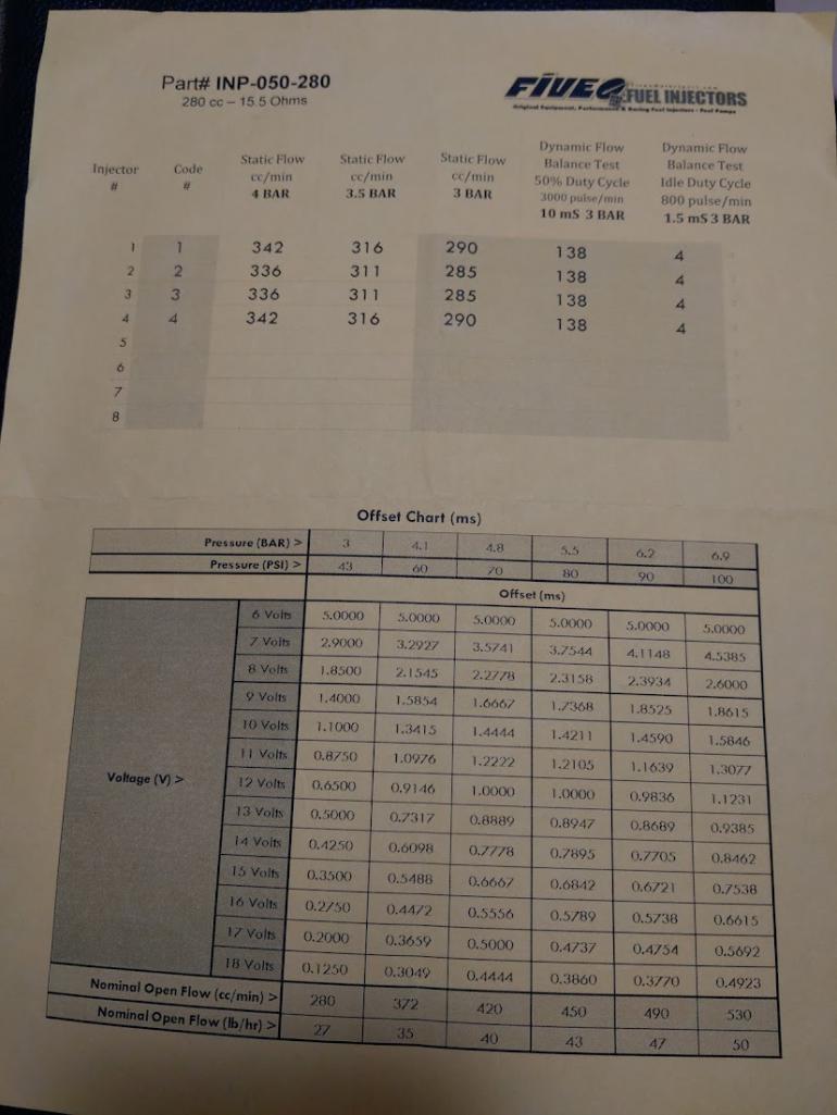 |
|
|
|
| bbrock |
Oct 12 2021, 12:35 PM
Post
#80
|
|
914 Guru Group: Members Posts: 5,269 Joined: 17-February 17 From: Montana Member No.: 20,845 Region Association: Rocky Mountains |
QUOTE(JamesM @ Oct 12 2021, 12:04 PM) QUOTE(VaccaRabite @ Oct 12 2021, 08:22 AM) I worry that the larger picture of building an EFI for a 4 banger aircooled motor is getting lost in the weeds here. These aren't exactly smooth running motors to begin with, and the engine bay is somewhat open to the elements. I'd reconsider using the Microquirt and adding some simplicity back into your equation. The operational differences between wasted spark and individually controlled plugs isn't going to be noticeable when you are driving the car, but will make it more challenging to build and tune - increasing the time before you are back to driving the car again. Zach I already tried to sell him on the easy button (well slightly easier button anyways). (IMG:style_emoticons/default/biggrin.gif) As someone who enjoys this stuff though I full support the effort to go completely overkill! (IMG:style_emoticons/default/beerchug.gif) Enabler! (IMG:style_emoticons/default/laugh.gif) QUOTE I'm actually sort of curious about what will be needed to properly dial in the injector timing and what sort(if any) difference it will wind up making. The tuning process with batch injection is fairly straight forward for the home mechanic with a wideband sensor but to fully dial in sequential injector timing... I suspect that's going to take some serious time and heavy equipment. Lots of stacked variables to deal with. You and me both. This is for sure going to be the biggest challenge. I may eat my words, but tuning for sequential spark doesn't look much different from wasted spark other than throwing some extra $ at hardware and a few configuration settings to tell the ECU the timing rules get applied across 4 channels instead of two. I'm sure there will be some head scratching in there but doesn't seem quite as daunting as sequential injection. Worst case if I get in too far over my head is that batch injection will still be an option. |
|
|
|
|
1 User(s) are reading this topic (1 Guests and 0 Anonymous Users)
0 Members:

|
Lo-Fi Version | Time is now: 8th July 2026 - 08:56 AM |
Invision Power Board
v9.1.4 © 2026 IPS, Inc.