|
|
|
Porsche, and the Porsche crest are registered trademarks of Dr. Ing. h.c. F. Porsche AG.
This site is not affiliated with Porsche in any way. Its only purpose is to provide an online forum for car enthusiasts. All other trademarks are property of their respective owners. |
|
|


| wonkipop |
 Apr 13 2022, 07:16 PM Apr 13 2022, 07:16 PM
Post
#1
|
|
Advanced Member  Group: Members Posts: 4,302 Joined: 6-May 20 From: north antarctica Member No.: 24,231 Region Association: NineFourteenerVille |
ok guys.
@JeffBowlsby and i have come across a historical question on the history/originality section of site. its been discussed for a year or so now. would be good to get to the bottom of it. not that it matters much to making your car run and (IMG:style_emoticons/default/driving-girl.gif) (IMG:style_emoticons/default/driving.gif) it. what we need is an image from the emissions warranty. from each model type. 1.7s, 1.8s, 2.0s and sixers for each model year. here is the anomaly. from my car. 74 1.8 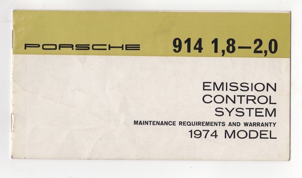  jeff has this up his excellent website of historical documentation. from a 73 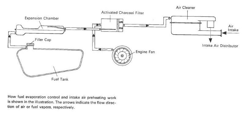 those of you with a sharp eye will notice they are different. see where fan hose goes. -------- the difference is of interest as it may be tied to how to correctly plumb the EVAP cannister after the change to engine bay location. or it may not? most of us probably don't care too much, but for those that might it could be interesting. another one of those 914 mysteries maybe. if you still have an emissions warranty, take a pic and post them up if you have time. (IMG:style_emoticons/default/beerchug.gif) |
   |

 
|
  |
Replies(1 - 19)
| bandjoey |
Apr 13 2022, 10:03 PM
Post
#2
|
|
bandjoey Group: Members Posts: 4,926 Joined: 26-September 07 From: Bedford Tx Member No.: 8,156 Region Association: Southwest Region |
Pelican Parts has full diagrams of all motors. A good place to look. People here might have those already just know of PP's.
|
|
|
|
| wonkipop |
Apr 13 2022, 10:47 PM
Post
#3
|
|
Advanced Member Group: Members Posts: 4,302 Joined: 6-May 20 From: north antarctica Member No.: 24,231 Region Association: NineFourteenerVille |
QUOTE(bandjoey @ Apr 13 2022, 10:03 PM)  Pelican Parts has full diagrams of all motors. A good place to look. People here might have those already just know of PP's. thanks @bandjoey . (IMG:style_emoticons/default/beerchug.gif) have most of that stuff already. pp material on 911s has been thoroughly and accurately tracked on that forum. looking for the same now with the 914. 1) tracking/verifying the two different systems known to be used on the 914. 2) finding where changeover happens and whether it is uniform changeover on all models or at different points in time for 1,.7/1.8 v six and 2.0. emissions warranties that came with cars (+ diagrams) are good data. |
|
|
|
| Montreal914 |
Apr 13 2022, 11:43 PM
Post
#4
|
|
Senior Member Group: Members Posts: 1,560 Joined: 8-August 10 From: Claremont, CA Member No.: 12,023 Region Association: Southern California |
Very interesting! (IMG:style_emoticons/default/popcorn[1].gif)
|
|
|
|
| Van B |
Apr 14 2022, 04:18 PM
Post
#5
|
|
Senior Member Group: Members Posts: 1,586 Joined: 20-October 21 From: Maryland Member No.: 26,011 Region Association: None |
@wonkipop I hope you like worms because you just opened a can of them lol!
Attached image(s) 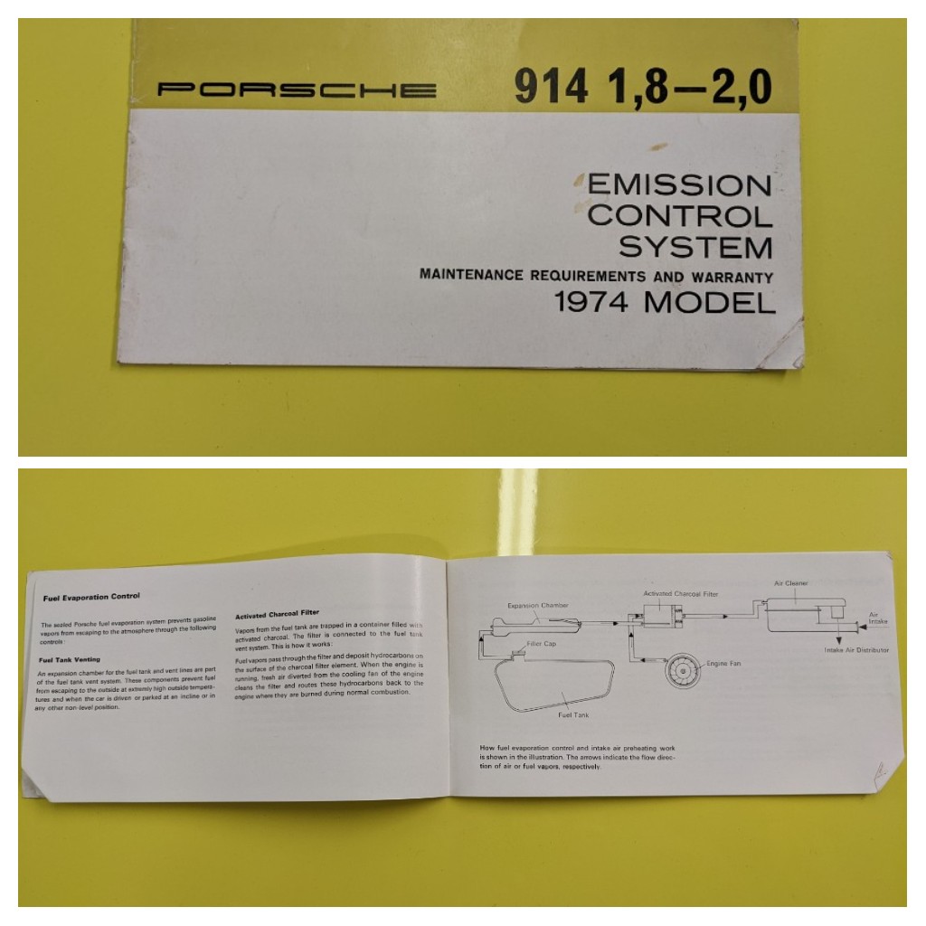
|
 |
|
| Van B |
Apr 14 2022, 04:19 PM
Post
#6
|
|
Senior Member Group: Members Posts: 1,586 Joined: 20-October 21 From: Maryland Member No.: 26,011 Region Association: None |
Needless to say, I'll be switching mine back to the PROPER configuration now! Hahaha!
|
|
|
|
| Jonathan Livesay |
Apr 14 2022, 05:13 PM
Post
#7
|
|
Senior Member Group: Members Posts: 741 Joined: 13-March 10 From: La Canada CA Member No.: 11,461 Region Association: None |
They show both in the service manual. Seems to me that one uses the air from the fan housing to push the fumes from the evap. tank into the throttle body while the other might push the fuel fumes back into the evap. tank. Am I missing something?
|
|
|
|
| Van B |
Apr 14 2022, 05:25 PM
Post
#8
|
|
Senior Member Group: Members Posts: 1,586 Joined: 20-October 21 From: Maryland Member No.: 26,011 Region Association: None |
QUOTE(Jonathan Livesay @ Apr 14 2022, 07:13 PM) They show both in the service manual. Seems to me that one uses the air from the fan housing to push the fumes from the evap. tank into the throttle body while the other might push the fuel fumes back into the evap. tank. Am I missing something? Well this is the mystery wonkipop is after. His car and mine were produced weeks apart and we have a different layout but the exact same parts. No difference in the canister, it's location, or anything else. Only an unexplained reverse hose layout... His is reversed (wonky) BTW, mine is normal! Just wanted to make that clear as this thread develops (IMG:style_emoticons/default/lol-2.gif) |
|
|
|
| JeffBowlsby |
Apr 14 2022, 05:44 PM
Post
#9
|
|
914 Wiring Harnesses Group: Members Posts: 8,510 Joined: 7-January 03 From: San Ramon CA Member No.: 104 Region Association: None |
Something I had forgotten about this diagram is that it inaccurately depicts the fuel vapor supply pipe in the charcoal filter can as extending through deep into the charcoal media. If this were so, then fuel vapors would be deposited to the far end of the canister and the supply air from the fan would direct the fuel vapors though the media so that the canister functions as intended
In reality that fuel vapor pipe in the plastic late 74 and later is a stubby, so that filtering is negligible when hooked up the 1973 way. Photo depicts the canister when opened looking into the far end. So this 1974 manual diagram works if the plastic can was built with the longer pipe, but it was not. I wonder how the inside of the 1973 and earlier metal can was constructed? Maybe they changed the piping due to intended can construction changes which may have affected the plumbing layout? Maybe the plastic cans were subject to cost reductions and they shortened the supply pipes? Attached image(s) 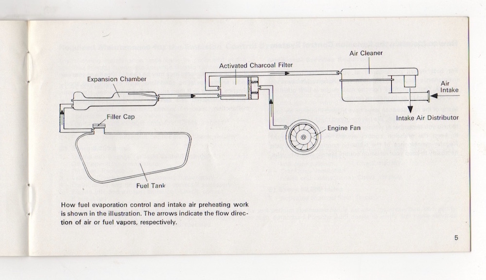 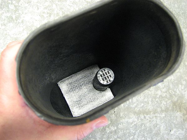
|
|
|
|
| Van B |
Apr 14 2022, 06:21 PM
Post
#10
|
|
Senior Member Group: Members Posts: 1,586 Joined: 20-October 21 From: Maryland Member No.: 26,011 Region Association: None |
Jeff, mine is the same and it’s a 12/73 build date.
Attached thumbnail(s) 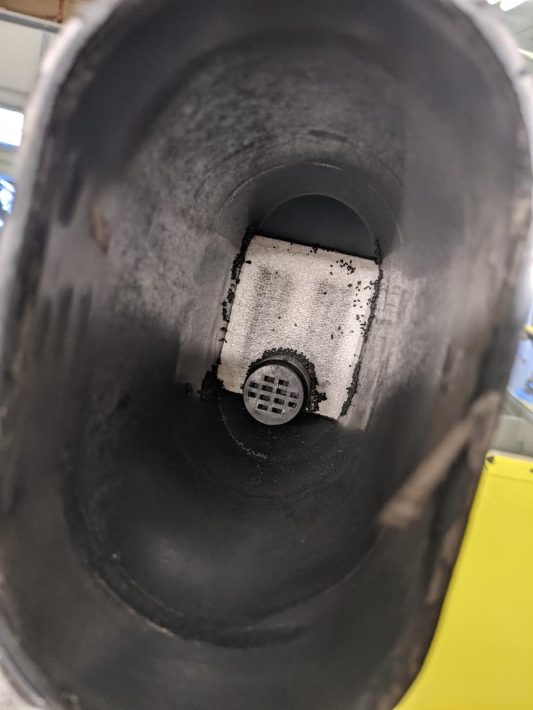
|
|
|
|
| StarBear |
Apr 14 2022, 06:34 PM
Post
#11
|
|
Senior Member Group: Members Posts: 1,885 Joined: 2-September 09 From: NJ Member No.: 10,753 Region Association: North East States |
From an engineer’s perspective (mine), the system work be more effective with a short stub in the given diagram. Presuming the function of the canister is to capture gas (petrol to some…. (IMG:style_emoticons/default/biggrin.gif) ) fumes during refueling:
1. Fumes get pushed up the gas tank through the chamber and into the canister, where the activated carbon “captures” the hydrocarbon fumes. A shorter stub allows the fumes to be exposed to more carbon. This, of course, assumes that the tank is being filled with the engine, hence fan, off. 2. When the engine (fan) is on, the positive pressure forces the hydrocarbons off of the carbon and into the air inlet, allowing the fumes to be combusted instead of being released into the atmosphere. A longer tube would expose the hydrocarbons to the charcoal on the far side of the canister, forcing them to be sent back across the carbon where they could get redeposited hence not evacuated from the canister. The fan air probably adds some back pressure to the chamber and the gas tank but not much; that pressure forces the fan air and fumes out the other outlet into the air intake. With the longer tube, yes the system would need to be plumbed differently so as to avoid that redistribution/redepositing situation. These are how industrial hydrocarbon emission reduction filters work, though often the carbon is removed and regenerated by exactly the same process as we have but in bigger, higher tech and probably more efficiently. Whew! (IMG:style_emoticons/default/rolleyes.gif) |
|
|
|
| wonkipop |
Apr 14 2022, 07:32 PM
Post
#12
|
|
Advanced Member Group: Members Posts: 4,302 Joined: 6-May 20 From: north antarctica Member No.: 24,231 Region Association: NineFourteenerVille |
QUOTE(JeffBowlsby @ Apr 14 2022, 05:44 PM) Something I had forgotten about this diagram is that it inaccurately depicts the fuel vapor supply pipe in the charcoal filter can as extending through deep into the charcoal media. If this were so, then fuel vapors would be deposited to the far end of the canister and the supply air from the fan would direct the fuel vapors though the media so that the canister functions as intended In reality that fuel vapor pipe in the plastic late 74 and later is a stubby, so that filtering is negligible when hooked up the 1973 way. Photo depicts the canister when opened looking into the far end. So this 1974 manual diagram works if the plastic can was built with the longer pipe, but it was not. I wonder how the inside of the 1973 and earlier metal can was constructed? Maybe they changed the piping due to intended can construction changes which may have affected the plumbing layout? Maybe the plastic cans were subject to cost reductions and they shortened the supply pipes? yep, its something like that jeff. and @Van B emission booklet is part of the mystery. and right in line with what i would have thought. something is going on right about the time the 1.8s come on line from nov 73 on. just like using up frunk cans first, they don't hand out the new booklets until the old ones are used up? none of it happens on exactly one car all together at one time. thanks for posting up the stuff guys. lets see what other members might have to throw more light on things in terms of their emission warranty booklet. particularly interested in see the 75 and 73 booklets. (IMG:style_emoticons/default/beerchug.gif) a thing to bear in mind at this point in time is whether it is assured that the booklets people have are original to the cars. after half a century some previous owners may have completed missing items with booklets purchased to replace lost ones. i do know mine is the one that came with the car. |
|
|
|
| wonkipop |
Apr 14 2022, 07:42 PM
Post
#13
|
|
Advanced Member Group: Members Posts: 4,302 Joined: 6-May 20 From: north antarctica Member No.: 24,231 Region Association: NineFourteenerVille |
QUOTE(StarBear @ Apr 14 2022, 06:34 PM) From an engineer’s perspective (mine), the system work be more effective with a short stub in the given diagram. Presuming the function of the canister is to capture gas (petrol to some…. (IMG:style_emoticons/default/biggrin.gif) ) fumes during refueling: 1. Fumes get pushed up the gas tank through the chamber and into the canister, where the activated carbon “captures” the hydrocarbon fumes. A shorter stub allows the fumes to be exposed to more carbon. This, of course, assumes that the tank is being filled with the engine, hence fan, off. 2. When the engine (fan) is on, the positive pressure forces the hydrocarbons off of the carbon and into the air inlet, allowing the fumes to be combusted instead of being released into the atmosphere. A longer tube would expose the hydrocarbons to the charcoal on the far side of the canister, forcing them to be sent back across the carbon where they could get redeposited hence not evacuated from the canister. The fan air probably adds some back pressure to the chamber and the gas tank but not much; that pressure forces the fan air and fumes out the other outlet into the air intake. With the longer tube, yes the system would need to be plumbed differently so as to avoid that redistribution/redepositing situation. These are how industrial hydrocarbon emission reduction filters work, though often the carbon is removed and regenerated by exactly the same process as we have but in bigger, higher tech and probably more efficiently. Whew! (IMG:style_emoticons/default/rolleyes.gif) without going into a debate about how they work which is not really the purpose of this thread, its really just to gather data at this point. - i would say this. you need to consider the behaviour of the can in the static phase. ie sitting there with the engine off. which is the other phase the can operates in, not just the dynamic state. secondly, the release of the fumes from the charcoal is akin to a chemical reaction. the carbon in the hydrocarbon is attracted to the carbon in the charcoal, thats how they get the fumes to stick to the activated charcoal. releasing the fumes is not so much blowing on them as flooding them with oxygen. the oxygen makes the charcoal release the hydrocarbons. thats really how the can works. on top of that the can is also the fuel tank ventilation "valve". it is what lets the air in to the tank to stop it being collapsed by a vacuum as you use up fuel. its a complex little device and its a passive device when compared to the systems used by most other manufacturers. but enough of that for now. its the emissions booklets we need to get hold of first. more material for jeff bowlsby's fab collection of documents on his website. |
|
|
|
| wonkipop |
Apr 14 2022, 08:05 PM
Post
#14
|
|
Advanced Member Group: Members Posts: 4,302 Joined: 6-May 20 From: north antarctica Member No.: 24,231 Region Association: NineFourteenerVille |
@Van B . @JeffBowlsby
re the different cans leading to different layouts. metal v plastic. i would say no. thats on the basis of what VW do with all their cars. VW plumb the cans as per my emission warranty in all their models from 1969 on. never change the plumbing. the can is updated along the way to plastic as per the 914. but nothing in the plumbing of which hose to which end of can changes for VWs. I think if we can get some more emissions warranties we might get some useful data. particularly whats either side of 1974 in the 73 and 75 model year cars. |
|
|
|
| wonkipop |
Apr 15 2022, 12:32 AM
Post
#15
|
|
Advanced Member Group: Members Posts: 4,302 Joined: 6-May 20 From: north antarctica Member No.: 24,231 Region Association: NineFourteenerVille |
@Van B
ok, you have not opened up a can of worms with your emissions warranty. you have shone a light on things. i just had a good look back through our EC engine research stuff. i think i can see something which puzzled me before doing EC engine research. take a look at this. (to slightly correct you, my car is not built within days of your car. mine is a good month and a half after yours and in 74 not 73). but this car (image following) we found in our research of EC engines is built within days of yours. it was built on the friday 7 dec 73 and yours on the monday 10 dec 73. i'd looked at it before and noted at first glance it had the same s curve hose from fan to lhs of can as my car but also noticed the can was around the other way from my car. pointy end of can oriented to lhs with fuel vapor line coming in that side. i thought someone might have reinstalled the can the wrong way around and messed it up. however its an extremely original car in all respects and in very good condition. and the can in this orientation with this configuration of plumbing would match your emissions warranty from nearly the same date of manufacture. 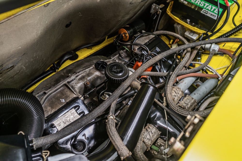 i would have loved to have been able to look inside the emissions warranty for this car. its exactly like yours with the same diagram? 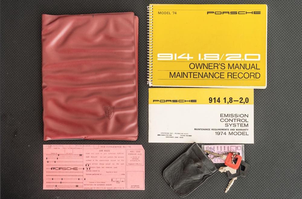 my question to you, which i have not thought to ask before - is which way is the can oriented in your car Van. is it with the pointy end to lhs and vapor line coming around to that end of it. along with fan line. and aircleaner line coming in to the rhs side which only has the one connection. you can possibly see where i am going with this? need a few more cars. just to work out if this yellow car is for real. i think it might be though. I have the same question for steve @StarBear as above. which way was can originally oriented in your car. yours is a 73 manufacture date like Vans. i know you lost the original emissions warranty steve and you have replaced it. but in the replacement one you have which diagram do you have in it anyway. is it the one like mine. or the one like vans. just to accumulate more material. and to rebuke that very naughty comment from jeff that mine was a misprint. (IMG:style_emoticons/default/smile.gif) (IMG:style_emoticons/default/stirthepot.gif) ------ now look at this one. my car is end of jan 74 car. it has the S shaped hose from fan to flat end of can with single port. the single port is on the lhs. on the rhs of can which is pointy side, it has the aircleaner hose and the vapor line. and all of that matches the diagram in the emissions warranty and is original in terms of the engine bay. i have never changed it. the car is still original and was competely original when i bought it in 89. now here is another example. this was also part of EC research material we had. this is the car the dr914 owned for a while in the AA collection. very low mileage, very original 1.8. the car is a feb 74 build. it exactly matches mine. the can is oriented the same way mine is. 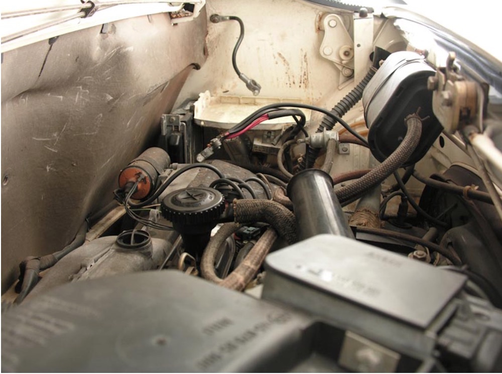 i would have loved to have seen the emissions warranty for the AA car. it matches the one that came with my car? ---------- i think we have been missing something else that was going on with the 1.8s. yes they shift the can from frunk to the engine bay. but it kind of blinded us maybe to a second change that happened which did not coincide with that. i had certainly been assuming that any change in the plumbing of the can co-incided with the change over to the engine bay can. i don't think it did now. i think it happens after that. its pretty subtle, but i no longer think that yellow car with the can oriented the other way around is wrong. its correct for when it was manufactured and it accords with the design in place at the time? its after that the design is amended and the plumbing is reversed. the same thing happens with 911s by the way. during the 1974 model year the plumbing in the can was reversed. i did some reading up on this on the P P forum and came across the thread on the 911 evap emissions system. a very extensive thread covering it all in detail and including the diagrams. a posting on that thread noted the changeover in 911s occured mid model year 1974. that would be right around december73/jan 74. i think we might be inching closer to cracking this mystery. there are 2 changes to the evap system in 74MY? 1) can location changed to engine bay. known to be very likely Nov 20 1973. 2) can plumbing revised? probably start of jan 74? maybe? having some more emissions warranties from 74 models (both 2.0 and 1.8) either side of dec 73 / jan 74 will start to shine more light on this. i doubt it makes any difference to the function of the can. and thats not the issue here with this thread - not which can works better in our opinion etc. i don't think anyone is right or anyone is wrong. what i am interested in is that porsche changed it. we know that. they changed it on the 911 and they changed it on the 914. all i want to know is the date they changed it. and the details of the change. which we just added potentially to with a detail previously overlooked. namely there were two versions of the rear firewall of the engine bay variant? if that is so, no one has picked up that little detail before. and it will only be on 1.8s too. not 2.0s. it will be in that period of 1.8s after the change from the frunk can up until sometime between 10 Dec 73 and 25 Jan 74. because they are only building 1.8s during that period. ------ i do have a view on the frunk cans in terms of how they work. and this is not to add to the back and forth about pushing or pulling air, or does the fan blow air, or does engine induction suck air etc and etc. and that is the frunk can had an inbuilt fault. look closely at the vapor line. it runs down hill from the expansion tank to the can. vapor condensing in the line can run down into the can as liquid fuel. thats one way to kill the charcoal in the can pretty quick. 911s with front mounted cans pre 74 do not have this fault. they have an extra expansion vent tank that prevents condensed vapor running down into the cannister. this extra expansion vent tank is not in the original 914 front mounted can scheme. i think fixing that fault is the reason for shifting the can to the engine bay. the vapor line descends to go through the tunnel and ascends to get to the can. any condensed vapor in the line runs downhill away from the can. this is separate from the matter of then going on to rearrange the plumbing to the can after that. more data is needed. though in the end its only of interest to a restorer seeking authenticity. and thats all this research is intended for. just to lodge the material to assist restoration and to have it filed in the originality section of the website for future owners. |
|
|
|
| Van B |
Apr 15 2022, 07:09 AM
Post
#16
|
|
Senior Member Group: Members Posts: 1,586 Joined: 20-October 21 From: Maryland Member No.: 26,011 Region Association: None |
@wonkipop
Mine is oriented as two hoses on the right, with the small evap hose on bottom. Further, when I took it apart, it was clear from the marks on the plastic case that it had been in only that orientation for it's whole life despite the fact that someone had refilled it (with the wrong pellets) at least once before. I think your originality pursuit is a good one even for guys like me who would never do concourse. For most of us, I think we'd all agree it's cool that 50yrs after this car was produced, we are still accumulating knowledge as a community that quite possibly wasn't fully known by anyone outside of the factory! Ref your email to the Porsche museum lol! Hopefully, some 2.0 guys will start chiming in soon *wink wink, nod, nod* |
|
|
|
| StarBear |
Apr 15 2022, 08:21 AM
Post
#17
|
|
Senior Member Group: Members Posts: 1,885 Joined: 2-September 09 From: NJ Member No.: 10,753 Region Association: North East States |
I checked and confirmed that mine is oriented and plumbed as shown on page 5 of the warranty booklet. Small fume inlet on small end, passenger/battery side.
@wonkipop ; you are correct- I don’t recall ever getting/ keeping my original booklet but got an “ok” original a while ago. @van b ; finally remembered to look at that “error” in the sales brochure. You are spot on with that photo of the guy loading the luggage. A few other pics show no bumper eyes in a few other photos and no front side marker lights in two photos of the yellow car. |
|
|
|
| wonkipop |
Apr 15 2022, 01:10 PM
Post
#18
|
|
Advanced Member Group: Members Posts: 4,302 Joined: 6-May 20 From: north antarctica Member No.: 24,231 Region Association: NineFourteenerVille |
QUOTE(StarBear @ Apr 15 2022, 08:21 AM) I checked and confirmed that mine is oriented and plumbed as shown on page 5 of the warranty booklet. Small fume inlet on small end, passenger/battery side. @wonkipop ; you are correct- I don’t recall ever getting/ keeping my original booklet but got an “ok” original a while ago. @van b ; finally remembered to look at that “error” in the sales brochure. You are spot on with that photo of the guy loading the luggage. A few other pics show no bumper eyes in a few other photos and no front side marker lights in two photos of the yellow car. what i was asking @StarBear was is the emissions warranty you picked up a version like Van B or is it like mine. see the fan hose hook up difference. just want to see which one it is. its going to need a few members with emissions warranties that came with cars to be able to place the two different diagrams in emissions warranty with the set up. 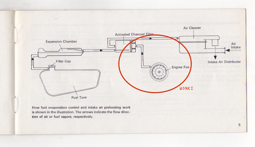 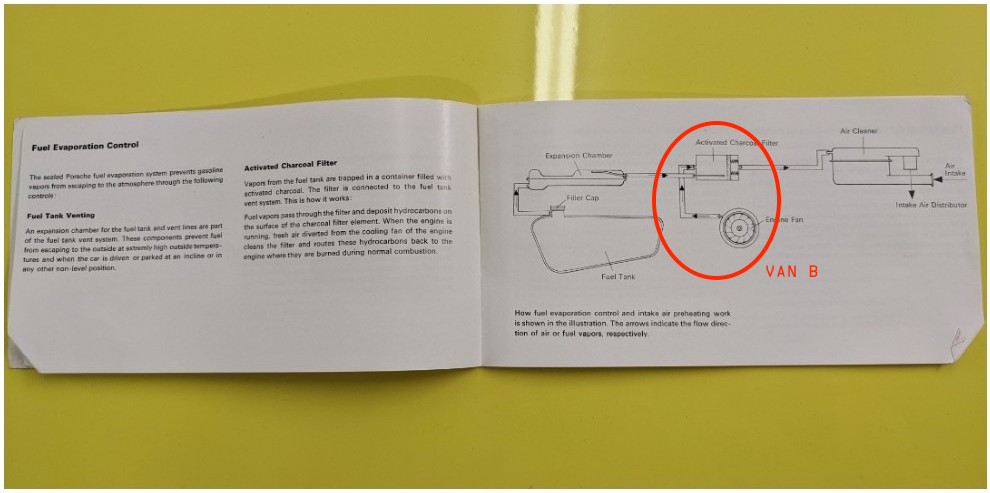 |
|
|
|
| wonkipop |
Apr 15 2022, 01:22 PM
Post
#19
|
|
Advanced Member Group: Members Posts: 4,302 Joined: 6-May 20 From: north antarctica Member No.: 24,231 Region Association: NineFourteenerVille |
QUOTE(Van B @ Apr 15 2022, 07:09 AM) @wonkipop Mine is oriented as two hoses on the right, with the small evap hose on bottom. Further, when I took it apart, it was clear from the marks on the plastic case that it had been in only that orientation for it's whole life despite the fact that someone had refilled it (with the wrong pellets) at least once before. I think your originality pursuit is a good one even for guys like me who would never do concourse. For most of us, I think we'd all agree it's cool that 50yrs after this car was produced, we are still accumulating knowledge as a community that quite possibly wasn't fully known by anyone outside of the factory! Ref your email to the Porsche museum lol! Hopefully, some 2.0 guys will start chiming in soon *wink wink, nod, nod* i don't do concourse either. reason being exactly this kind of stuff. as we can see from what we have been doing with EC-A or EC-B etc, there are no experts when it comes to this. its never been researched. jeff bowlsby got me fired up on this with his revelation about the EC A and B versions. boy - thats one for the history books. they all said the EC engine was a 50 state car. i also admire how VW did one of the best jobs during the malaise era. with such small engines in their cars they could not afford to lose power output. they did a remarkable job when you compare them to just how much the USA domestic manufacturers suffered in terms of performance loss. |
|
|
|
| wonkipop |
Apr 15 2022, 01:34 PM
Post
#20
|
|
Advanced Member Group: Members Posts: 4,302 Joined: 6-May 20 From: north antarctica Member No.: 24,231 Region Association: NineFourteenerVille |
QUOTE(StarBear @ Apr 15 2022, 08:21 AM) I checked and confirmed that mine is oriented and plumbed as shown on page 5 of the warranty booklet. Small fume inlet on small end, passenger/battery side. @wonkipop ; you are correct- I don’t recall ever getting/ keeping my original booklet but got an “ok” original a while ago. @van b ; finally remembered to look at that “error” in the sales brochure. You are spot on with that photo of the guy loading the luggage. A few other pics show no bumper eyes in a few other photos and no front side marker lights in two photos of the yellow car. slight diversion. @StarBear and @Van B by bumper eyes i'm guessing you guys are talking about covers for holes in the bumpers where tits mounted on USA models. here are my photos of dr. marchant car in porsche museum from 10 years back. euro spec 74s did not have drilled holes or covers. 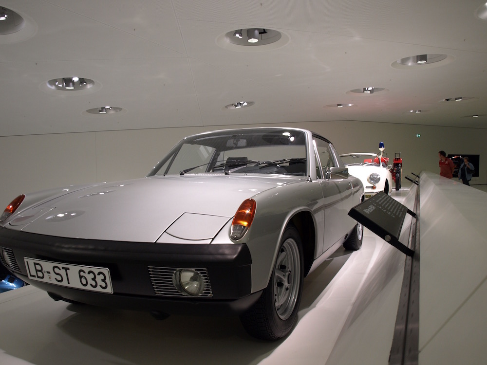 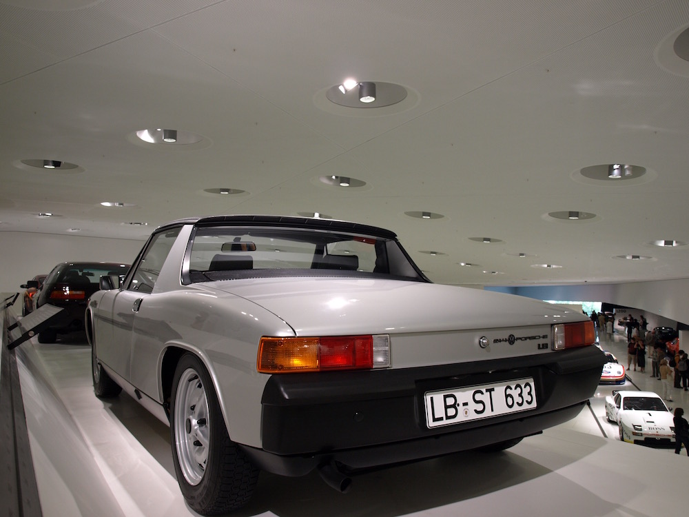 |
|
|
|
|
1 User(s) are reading this topic (1 Guests and 0 Anonymous Users)
0 Members:

|
Lo-Fi Version | Time is now: 18th May 2024 - 09:58 AM |
Invision Power Board
v9.1.4 © 2024 IPS, Inc.