|
|
|
Porsche, and the Porsche crest are registered trademarks of Dr. Ing. h.c. F. Porsche AG.
This site is not affiliated with Porsche in any way. Its only purpose is to provide an online forum for car enthusiasts. All other trademarks are property of their respective owners. |
|
|


| bbrock |
 Jul 28 2022, 07:17 PM Jul 28 2022, 07:17 PM
Post
#1
|
|
914 Guru  Group: Members Posts: 5,269 Joined: 17-February 17 From: Montana Member No.: 20,845 Region Association: Rocky Mountains |
Right after ordering a complete Car Magic kit to convert my windshield washer to electric, I read Sir Andy's excellent tech article on the conversion. The idea of pulling power for the washer pump off the intermittent wiper feed so the washer is activated by pulling back on the wiper lever was too elegant not to try.
I happened to have this nifty vintage VW style splitter I bought some time ago for not other reason than I thought it might come in handy for some future custom wiring project. It was just the ticket for splitting off of my intermittent washer relay to power the washer pump. 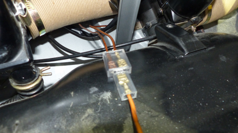 After hooking everything up, I pulled back on the wiper lever and HUZZAH! The washers squirted and the wipers ran for two sweeps and parked. Pretty slick! I couldn't understand how the intermittent wipers would work when the lever was pulled down to turn the intermittent wipers on. I pull down on the lever to test them and nothing. As soon as I unplug the washer pump, the intermittent wipers start running. I'm not sure how the intermittent relay works, but thinking the timer is from charging a capacitor which then "bump starts" the wipers to run a single cycle. Is there is a reasonably simple way to isolate the pump so it allows the intermittent mechanism to run without activating the washer pump? Could be a fun project. Or should I just go back to the original plan of installing the Car Magic switch? I just like the idea of minimizing the wiring. |
   |

 
|
Posts in this topic
 bbrock Attention Electrical Gurus Jul 28 2022, 07:17 PM
 Spoke @bbrock
Do you have documentation describing the... Jul 29 2022, 09:20 AM
Spoke @bbrock
Do you have documentation describing the... Jul 29 2022, 09:20 AM
 bbrock
@[url=http://www.914world.com/bbs2/index.php?show... Jul 29 2022, 10:04 AM Superhawk996
Instead of the kit, I'm branching off the br... Jul 31 2022, 01:46 PM bbrock
Instead of the kit, I'm branching off the b... Jul 31 2022, 01:51 PM dr914@autoatlanta.com intermittent is activated by pulling the stalk dow... Jul 29 2022, 11:02 AM FlacaProductions As George says - but do you have the tab broken ou... Jul 29 2022, 11:53 AM bbrock Let's back up a bit. My intermittent wipers w... Jul 29 2022, 12:45 PM lesorubcheek It's kinda difficult looking at the wiring dia... Jul 29 2022, 01:45 PM bbrock
It's kinda difficult looking at the wiring di... Jul 29 2022, 04:52 PM lesorubcheek I know the feeling. You just can't let this go... Jul 29 2022, 07:47 PM bbrock
I know the feeling. You just can't let this g... Jul 29 2022, 10:52 PM Spoke I've been following this discussion but haven... Jul 31 2022, 04:44 PM bbrock
I've been following this discussion but haven... Jul 31 2022, 05:09 PM Spoke
Ah! There is something I should have explai... Jul 31 2022, 06:10 PM bbrock
[b]@[url=http://www.914world.com/bbs2/index.php?... Jul 31 2022, 06:45 PM Spoke @bbrock
I'm not sure how pulling back on the... Jul 29 2022, 09:54 PM bbrock
[b]@[url=http://www.914world.com/bbs2/index.php?s... Jul 29 2022, 10:40 PM bbrock My previous post was incorrect. It was dark in th... Jul 30 2022, 10:29 AM Superhawk996 I apologize I'm worthless for this thread. Al... Jul 30 2022, 10:36 AM bbrock
I apologize I'm worthless for this thread. A... Jul 30 2022, 11:20 AM Superhawk996
I apologize I'm worthless for this thread. ... Jul 30 2022, 11:38 AM bbrock
Can you post a more comprehensive circuit diagra... Jul 30 2022, 12:41 PM Superhawk996
The circuit is so simple there is really no need... Jul 30 2022, 01:18 PM bbrock
The circuit is so simple there is really no nee... Jul 30 2022, 03:51 PM Bartlett 914 It has been awhile since I worked with the washer ... Jul 30 2022, 01:08 PM bbrock I went ahead and ordered one of these low voltage ... Jul 31 2022, 10:16 AM Superhawk996
I went ahead and ordered one of these low voltage... Jul 31 2022, 10:27 AM windforfun
I went ahead and ordered one of these low voltag... Jul 31 2022, 10:32 AM bbrock
I went ahead and ordered one of these low voltag... Jul 31 2022, 11:29 AM Superhawk996
Here, I added the "complicated" part f... Jul 31 2022, 11:43 AM Superhawk996 @bbrock
Do you actually have your intermittent r... Jul 31 2022, 12:50 PM bbrock
[b]@[url=http://www.914world.com/bbs2/index.php?s... Jul 31 2022, 01:42 PM Superhawk996
You're explanation of the grn/wht wire make... Jul 31 2022, 01:58 PM bbrock
[quote name='bbrock' post='3019478' date='Jul 31 ... Jul 31 2022, 02:07 PM bbrock
No -- that brown / black doesn't get ground t... Jul 31 2022, 02:26 PM lesorubcheek
Anyway, the DMM says this. Pull back the lever a... Jul 31 2022, 02:54 PM Superhawk996 just saw your other post
Yes - the schematics are... Jul 31 2022, 01:48 PM bbrock
just saw your other post
Yes - the schematics ar... Jul 31 2022, 01:59 PM bbrock And I agree about the confusion. I'm not a fa... Jul 31 2022, 02:09 PM Superhawk996 I don't think you'll be able to get the co... Jul 31 2022, 02:26 PM bbrock
I don't think you'll be able to get the c... Jul 31 2022, 02:31 PM Superhawk996 :idea:
Ok now I think I understand your idea bet... Jul 31 2022, 02:58 PM bbrock
:idea:
Ok now I think I understand your idea be... Jul 31 2022, 03:47 PM Superhawk996 Now that I've had some time to think about the... Jul 31 2022, 04:10 PM bbrock
Now that I've had some time to think about th... Jul 31 2022, 04:57 PM Superhawk996
Don't think that one will work. It switches... Jul 31 2022, 05:17 PM Spoke
Now that I've had some time to think about t... Jul 31 2022, 06:31 PM bbrock
I think I agree with you about the switching. Th... Jul 31 2022, 06:56 PM Spoke
Yes, but the voltage readings are small. In the... Jul 31 2022, 07:39 PM bbrock
Yes, but the voltage readings are small. In th... Jul 31 2022, 08:42 PM Superhawk996
I shouldn't have called this a "simple... Aug 1 2022, 06:38 AM bbrock
I shouldn't have called this a "simple... Aug 1 2022, 08:39 AM Superhawk996
I still say we didn't need the full schematic... Aug 1 2022, 09:03 AM lesorubcheek If the goal is to have an open circuit at S on the... Aug 1 2022, 12:03 PM Spoke
If the goal is to have an open circuit at S on th... Aug 1 2022, 05:08 PM bbrock
[quote name='lesorubcheek' post='3019726' date='A... Aug 1 2022, 06:18 PM lesorubcheek
[quote name='lesorubcheek' post='3019726' date='... Aug 1 2022, 06:34 PM bbrock
I did . . . just because that is the way I... Aug 1 2022, 01:40 PM Superhawk996 Here's the blurb from the 73' owner's ... Aug 1 2022, 06:53 AM bbrock GENIUS!
Dug through my spares and found an un... Aug 1 2022, 06:55 PM Spoke Sounds like the intermittent relay needs a couple ... Aug 2 2022, 03:50 AM bbrock
Sounds like the intermittent relay needs a couple... Aug 2 2022, 08:12 AM Spoke @bbrock
Either BY880 diodes will work. According... Aug 2 2022, 08:31 AM bbrock
@[url=http://www.914world.com/bbs2/index.php?show... Aug 2 2022, 10:55 AM Superhawk996 Getting close. :trophy: Aug 2 2022, 08:35 AM bbrock Unbelievable! The diodes arrived yesterday. ... Aug 6 2022, 02:26 PM bbrock Well that escalated quickly :blink:
The new VDO ... Aug 13 2022, 07:44 PM 930cabman
[b]Well that escalated quickly :blink:
The new ... Aug 14 2022, 09:30 AM bbrock
I may be able to piece together an original washe... Aug 14 2022, 11:32 AM FlacaProductions Very cool - and everyone likes a graceful recovery... Aug 13 2022, 10:29 PM davep A very interesting discussion. I have been kicking... Aug 13 2022, 10:31 PM bbrock
A very interesting discussion. I have been kickin... Aug 13 2022, 11:33 PM Superhawk996 :cool: Bookmarking this thread. Aug 14 2022, 08:38 AM
bbrock
@[url=http://www.914world.com/bbs2/index.php?show... Jul 29 2022, 10:04 AM Superhawk996
Instead of the kit, I'm branching off the br... Jul 31 2022, 01:46 PM bbrock
Instead of the kit, I'm branching off the b... Jul 31 2022, 01:51 PM dr914@autoatlanta.com intermittent is activated by pulling the stalk dow... Jul 29 2022, 11:02 AM FlacaProductions As George says - but do you have the tab broken ou... Jul 29 2022, 11:53 AM bbrock Let's back up a bit. My intermittent wipers w... Jul 29 2022, 12:45 PM lesorubcheek It's kinda difficult looking at the wiring dia... Jul 29 2022, 01:45 PM bbrock
It's kinda difficult looking at the wiring di... Jul 29 2022, 04:52 PM lesorubcheek I know the feeling. You just can't let this go... Jul 29 2022, 07:47 PM bbrock
I know the feeling. You just can't let this g... Jul 29 2022, 10:52 PM Spoke I've been following this discussion but haven... Jul 31 2022, 04:44 PM bbrock
I've been following this discussion but haven... Jul 31 2022, 05:09 PM Spoke
Ah! There is something I should have explai... Jul 31 2022, 06:10 PM bbrock
[b]@[url=http://www.914world.com/bbs2/index.php?... Jul 31 2022, 06:45 PM Spoke @bbrock
I'm not sure how pulling back on the... Jul 29 2022, 09:54 PM bbrock
[b]@[url=http://www.914world.com/bbs2/index.php?s... Jul 29 2022, 10:40 PM bbrock My previous post was incorrect. It was dark in th... Jul 30 2022, 10:29 AM Superhawk996 I apologize I'm worthless for this thread. Al... Jul 30 2022, 10:36 AM bbrock
I apologize I'm worthless for this thread. A... Jul 30 2022, 11:20 AM Superhawk996
I apologize I'm worthless for this thread. ... Jul 30 2022, 11:38 AM bbrock
Can you post a more comprehensive circuit diagra... Jul 30 2022, 12:41 PM Superhawk996
The circuit is so simple there is really no need... Jul 30 2022, 01:18 PM bbrock
The circuit is so simple there is really no nee... Jul 30 2022, 03:51 PM Bartlett 914 It has been awhile since I worked with the washer ... Jul 30 2022, 01:08 PM bbrock I went ahead and ordered one of these low voltage ... Jul 31 2022, 10:16 AM Superhawk996
I went ahead and ordered one of these low voltage... Jul 31 2022, 10:27 AM windforfun
I went ahead and ordered one of these low voltag... Jul 31 2022, 10:32 AM bbrock
I went ahead and ordered one of these low voltag... Jul 31 2022, 11:29 AM Superhawk996
Here, I added the "complicated" part f... Jul 31 2022, 11:43 AM Superhawk996 @bbrock
Do you actually have your intermittent r... Jul 31 2022, 12:50 PM bbrock
[b]@[url=http://www.914world.com/bbs2/index.php?s... Jul 31 2022, 01:42 PM Superhawk996
You're explanation of the grn/wht wire make... Jul 31 2022, 01:58 PM bbrock
[quote name='bbrock' post='3019478' date='Jul 31 ... Jul 31 2022, 02:07 PM bbrock
No -- that brown / black doesn't get ground t... Jul 31 2022, 02:26 PM lesorubcheek
Anyway, the DMM says this. Pull back the lever a... Jul 31 2022, 02:54 PM Superhawk996 just saw your other post
Yes - the schematics are... Jul 31 2022, 01:48 PM bbrock
just saw your other post
Yes - the schematics ar... Jul 31 2022, 01:59 PM bbrock And I agree about the confusion. I'm not a fa... Jul 31 2022, 02:09 PM Superhawk996 I don't think you'll be able to get the co... Jul 31 2022, 02:26 PM bbrock
I don't think you'll be able to get the c... Jul 31 2022, 02:31 PM Superhawk996 :idea:
Ok now I think I understand your idea bet... Jul 31 2022, 02:58 PM bbrock
:idea:
Ok now I think I understand your idea be... Jul 31 2022, 03:47 PM Superhawk996 Now that I've had some time to think about the... Jul 31 2022, 04:10 PM bbrock
Now that I've had some time to think about th... Jul 31 2022, 04:57 PM Superhawk996
Don't think that one will work. It switches... Jul 31 2022, 05:17 PM Spoke
Now that I've had some time to think about t... Jul 31 2022, 06:31 PM bbrock
I think I agree with you about the switching. Th... Jul 31 2022, 06:56 PM Spoke
Yes, but the voltage readings are small. In the... Jul 31 2022, 07:39 PM bbrock
Yes, but the voltage readings are small. In th... Jul 31 2022, 08:42 PM Superhawk996
I shouldn't have called this a "simple... Aug 1 2022, 06:38 AM bbrock
I shouldn't have called this a "simple... Aug 1 2022, 08:39 AM Superhawk996
I still say we didn't need the full schematic... Aug 1 2022, 09:03 AM lesorubcheek If the goal is to have an open circuit at S on the... Aug 1 2022, 12:03 PM Spoke
If the goal is to have an open circuit at S on th... Aug 1 2022, 05:08 PM bbrock
[quote name='lesorubcheek' post='3019726' date='A... Aug 1 2022, 06:18 PM lesorubcheek
[quote name='lesorubcheek' post='3019726' date='... Aug 1 2022, 06:34 PM bbrock
I did . . . just because that is the way I... Aug 1 2022, 01:40 PM Superhawk996 Here's the blurb from the 73' owner's ... Aug 1 2022, 06:53 AM bbrock GENIUS!
Dug through my spares and found an un... Aug 1 2022, 06:55 PM Spoke Sounds like the intermittent relay needs a couple ... Aug 2 2022, 03:50 AM bbrock
Sounds like the intermittent relay needs a couple... Aug 2 2022, 08:12 AM Spoke @bbrock
Either BY880 diodes will work. According... Aug 2 2022, 08:31 AM bbrock
@[url=http://www.914world.com/bbs2/index.php?show... Aug 2 2022, 10:55 AM Superhawk996 Getting close. :trophy: Aug 2 2022, 08:35 AM bbrock Unbelievable! The diodes arrived yesterday. ... Aug 6 2022, 02:26 PM bbrock Well that escalated quickly :blink:
The new VDO ... Aug 13 2022, 07:44 PM 930cabman
[b]Well that escalated quickly :blink:
The new ... Aug 14 2022, 09:30 AM bbrock
I may be able to piece together an original washe... Aug 14 2022, 11:32 AM FlacaProductions Very cool - and everyone likes a graceful recovery... Aug 13 2022, 10:29 PM davep A very interesting discussion. I have been kicking... Aug 13 2022, 10:31 PM bbrock
A very interesting discussion. I have been kickin... Aug 13 2022, 11:33 PM Superhawk996 :cool: Bookmarking this thread. Aug 14 2022, 08:38 AM  |
1 User(s) are reading this topic (1 Guests and 0 Anonymous Users)
0 Members:

|
Lo-Fi Version | Time is now: 28th June 2026 - 07:28 PM |
Invision Power Board
v9.1.4 © 2026 IPS, Inc.