|
|
|
Porsche, and the Porsche crest are registered trademarks of Dr. Ing. h.c. F. Porsche AG.
This site is not affiliated with Porsche in any way. Its only purpose is to provide an online forum for car enthusiasts. All other trademarks are property of their respective owners. |
|
|

  |

| shredtherad |
 May 18 2023, 08:00 AM May 18 2023, 08:00 AM
Post
#1
|
|
Member  Group: Members Posts: 86 Joined: 17-May 22 From: Longmont, Colorado Member No.: 26,559 Region Association: Rocky Mountains |
I got the tank out, removed the old lines, got the fuel lines through the tunnel but I am stuck on how the engine bay lines work.
Anyone have any photos of how they worked that one? Or what the layout looks like? Also, anyone have a schematic on how the layout looks for the fuel pump relocation to the front under the car but the steering rack? I must suck at searching because I was unable to find what I was looking for... thanks all! |
   |

 
|
| nditiz1 |
May 18 2023, 08:13 AM
Post
#2
|
|
Senior Member Group: Members Posts: 1,180 Joined: 26-May 15 From: Mount Airy, Maryland Member No.: 18,763 Region Association: MidAtlantic Region |
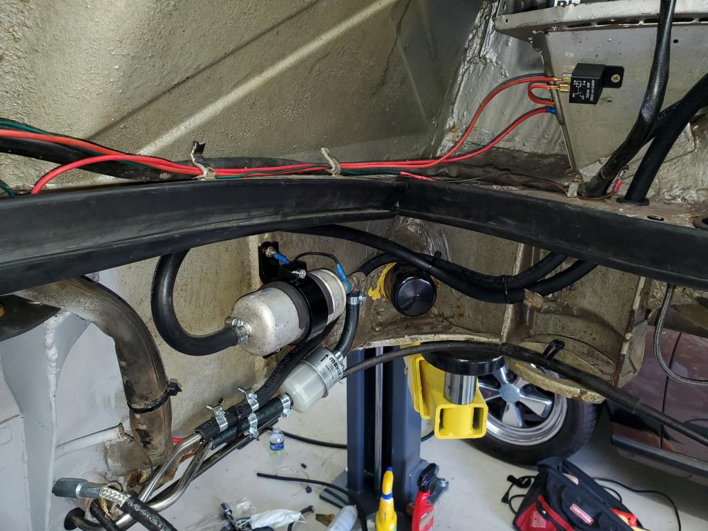
Before I moved it to the frunk
 |
|
|
|
| r_towle |
May 18 2023, 08:17 AM
Post
#3
|
|
Custom Member Group: Members Posts: 24,571 Joined: 9-January 03 From: Taxachusetts Member No.: 124 Region Association: North East States |
If the pump is in front, the feed line (rubber) goes up the passenger long, along the back trunk wall, then connects to the fuel pressure regulator.
Off the regulator feeds the driver side injectors, then from there to the passenger side injectors, then back to the return line to the tank. I guess it’s up to you, but the regulator is first, then injectors |
|
|
|
| NARP74 |
May 18 2023, 08:22 AM
Post
#4
|
|
Senior Member Group: Members Posts: 1,056 Joined: 29-July 20 From: Colorado, USA, Earth Member No.: 24,549 Region Association: Rocky Mountains |
Lots of results here. You can narrow your search as needed.
site:914world.com stainless steel fuel lines |
|
|
|
| NARP74 |
May 18 2023, 08:27 AM
Post
#5
|
|
Senior Member Group: Members Posts: 1,056 Joined: 29-July 20 From: Colorado, USA, Earth Member No.: 24,549 Region Association: Rocky Mountains |
|
|
|
|
| sportlicherFahrer |
May 18 2023, 10:21 AM
Post
#6
|
|
Nothing to see here. Group: Members Posts: 1,076 Joined: 18-April 05 From: Tacoma, WA Member No.: 3,945 Region Association: Pacific Northwest |
QUOTE(r_towle @ May 18 2023, 07:17 AM)  If the pump is in front, the feed line (rubber) goes up the passenger long, along the back trunk wall, then connects to the fuel pressure regulator. Off the regulator feeds the driver side injectors, then from there to the passenger side injectors, then back to the return line to the tank. I guess it’s up to you, but the regulator is first, then injectors Got that backwards. Pressure goes from the tunnel to the #3/#4 rail, across the top of the engine to the #1/#2 rail, then to the regulator. Ljet has the CSV in the middle of the run between banks, and Djet has it off the #1/#2 rail. Return goes from the regulator, across the back of the engine/rear firewall, back down to the tunnel. @iankarr did a video on the install: https://youtu.be/IDFsZoI_W3g Pelican link for hose diagrams. For late model under-car routing look at the 1.8 diagram: https://www.pelicanparts.com/914/technical_...el_diagrams.htm |
|
|
|
| shredtherad |
May 18 2023, 10:28 AM
Post
#7
|
|
Member Group: Members Posts: 86 Joined: 17-May 22 From: Longmont, Colorado Member No.: 26,559 Region Association: Rocky Mountains |
QUOTE(NARP74 @ May 18 2023, 08:27 AM) Cool, thanks. I had looked at this before. Didn't really help me with the engine bay ss lines that are included with kit and the photo that is included with the kit is rubbish... haha. Plus the pump is up front now too... I will just figure it out, seems like the only way (IMG:style_emoticons/default/smile.gif) |
|
|
|
| shredtherad |
May 18 2023, 10:50 AM
Post
#8
|
|
Member Group: Members Posts: 86 Joined: 17-May 22 From: Longmont, Colorado Member No.: 26,559 Region Association: Rocky Mountains |
QUOTE(sportlicherFahrer @ May 18 2023, 10:21 AM) QUOTE(r_towle @ May 18 2023, 07:17 AM) If the pump is in front, the feed line (rubber) goes up the passenger long, along the back trunk wall, then connects to the fuel pressure regulator. Off the regulator feeds the driver side injectors, then from there to the passenger side injectors, then back to the return line to the tank. I guess it’s up to you, but the regulator is first, then injectors Got that backwards. Pressure goes from the tunnel to the #3/#4 rail, across the top of the engine to the #1/#2 rail, then to the regulator. Ljet has the CSV in the middle of the run between banks, and Djet has it off the #1/#2 rail. Return goes from the regulator, across the back of the engine/rear firewall, back down to the tunnel. @iankarr did a video on the install: https://youtu.be/IDFsZoI_W3g Pelican link for hose diagrams. For late model under-car routing look at the 1.8 diagram: https://www.pelicanparts.com/914/technical_...el_diagrams.htm thanks! i looked at that video, he skips over the lines in the engine bay, that is the part I am sort of lost on, how the Shorter stainless lines are run in the engine bay. |
|
|
|
| sportlicherFahrer |
May 18 2023, 11:00 AM
Post
#9
|
|
Nothing to see here. Group: Members Posts: 1,076 Joined: 18-April 05 From: Tacoma, WA Member No.: 3,945 Region Association: Pacific Northwest |
QUOTE(shredtherad @ May 18 2023, 09:50 AM) thanks! i looked at that video, he skips over the lines in the engine bay, that is the part I am sort of lost on, how the Shorter stainless lines are run in the engine bay. They poke through grommets on the shelf under the battery pedestal. Larger bend radius(in regards to the "hooked" end that goes towards the top rear passenger corner of the engine compartment) line goes in the forward hole and is usually used for return, smaller bend radius in the aft hole and is usually used for pressure as it is just a little closer to the #3/#4 fuel rail. In reality, you can use whichever one you want for pressure or return as long as you mark them somehow to avoid confusion when you're completing the circuit. Mine were very similar, so I just used red nail polish to mark the pressure line a couple inches away from the end. Basic point is that the longer more-straight end goes down through the shelf, and the hooked end sticks up in the engine bay aft of the battery for both lines. Edit: you can see the top end of the lines at 9:38 in Ian's video. Note the MPS mounted above the shelf and the rain tray drain hose for reference. The thick black cable to the left of the lines is the positive battery cable going from the battery to the starter. |
|
|
|
| r_towle |
May 18 2023, 11:05 AM
Post
#10
|
|
Custom Member Group: Members Posts: 24,571 Joined: 9-January 03 From: Taxachusetts Member No.: 124 Region Association: North East States |
exactly backwards of what I said....lol
Diagrams help. Attached image(s) 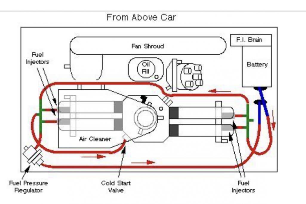
|
|
|
|
| shredtherad |
May 18 2023, 11:06 AM
Post
#11
|
|
Member Group: Members Posts: 86 Joined: 17-May 22 From: Longmont, Colorado Member No.: 26,559 Region Association: Rocky Mountains |
QUOTE(sportlicherFahrer @ May 18 2023, 11:00 AM) QUOTE(shredtherad @ May 18 2023, 09:50 AM) thanks! i looked at that video, he skips over the lines in the engine bay, that is the part I am sort of lost on, how the Shorter stainless lines are run in the engine bay. They poke through grommets on the shelf under the battery pedestal. Larger bend radius(in regards to the "hooked" end that goes towards the top rear passenger corner of the engine compartment) line goes in the forward hole and is usually used for return, smaller bend radius in the aft hole and is usually used for pressure as it is just a little closer to the #3/#4 fuel rail. In reality, you can use whichever one you want for pressure or return as long as you mark them somehow to avoid confusion when you're completing the circuit. Mine were very similar, so I just used red nail polish to mark the pressure line a couple inches away from the end. Basic point is that the longer more-straight end goes down through the shelf, and the hooked end sticks up in the engine bay aft of the battery for both lines. Sweet! thanks mate. I assume a reducer is needed between the engine bay ss line and the fuel lines in the rail for the supply line? Thanks for helping, I am a noob to working on cars :/ |
|
|
|
| sportlicherFahrer |
May 18 2023, 11:15 AM
Post
#12
|
|
Nothing to see here. Group: Members Posts: 1,076 Joined: 18-April 05 From: Tacoma, WA Member No.: 3,945 Region Association: Pacific Northwest |
QUOTE(shredtherad @ May 18 2023, 10:06 AM) Sweet! thanks mate. I assume a reducer is needed between the engine bay ss line and the fuel lines in the rail for the supply line? You're welcome! Sounds like you have the early large diameter feed line in the tunnel? The best solution is to use one of the reducers Tangerine sells, or something similar if you happen to have a local source. Stretching the small hose to the large line can damage or fatigue the hose causing leaks, and clamping a large hose to the smaller tube will almost always result in a leak. Up to you on how and where you want to fit a transition in. https://tangerineracing.com/shop/ols/produc...e-adapter-piece |
|
|
|
| shredtherad |
May 18 2023, 11:30 AM
Post
#13
|
|
Member Group: Members Posts: 86 Joined: 17-May 22 From: Longmont, Colorado Member No.: 26,559 Region Association: Rocky Mountains |
QUOTE(sportlicherFahrer @ May 18 2023, 11:15 AM) QUOTE(shredtherad @ May 18 2023, 10:06 AM) Sweet! thanks mate. I assume a reducer is needed between the engine bay ss line and the fuel lines in the rail for the supply line? You're welcome! Sounds like you have the early large diameter feed line in the tunnel? The best solution is to use one of the reducers Tangerine sells, or something similar if you happen to have a local source. Stretching the small hose to the large line can damage or fatigue the hose causing leaks, and clamping a large hose to the smaller tube will almost always result in a leak. Up to you on how and where you want to fit a transition in. https://tangerineracing.com/shop/ols/produc...e-adapter-piece Cool, I got a couple already! I planned a little bit. I think I got the layout down. but not sure what #1 in my photo is and there is a hose that was going to to the FP before I moved it #2 Attached image(s) 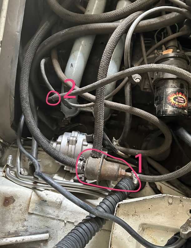
|
|
|
|
| sportlicherFahrer |
May 18 2023, 12:16 PM
Post
#14
|
|
Nothing to see here. Group: Members Posts: 1,076 Joined: 18-April 05 From: Tacoma, WA Member No.: 3,945 Region Association: Pacific Northwest |
Great! (IMG:style_emoticons/default/beer.gif)
#1 is the Decel Valve, and #2 looks to be the same hose that is attached to the right hand side of #1. If it is, it should be connected to manifold vacuum, as should the port pointed up in relation to the photo. Port on the left should be routed to the air filter housing. |
|
|
|
| shredtherad |
May 18 2023, 12:28 PM
Post
#15
|
|
Member Group: Members Posts: 86 Joined: 17-May 22 From: Longmont, Colorado Member No.: 26,559 Region Association: Rocky Mountains |
QUOTE(sportlicherFahrer @ May 18 2023, 12:16 PM) Great! (IMG:style_emoticons/default/beer.gif) #1 is the Decel Valve, and #2 looks to be the same hose that is attached to the right hand side of #1. If it is, it should be connected to manifold vacuum, as should the port pointed up in relation to the photo. Port on the left should be routed to the air filter housing. Ok, thanks. man, I wish I shot photos before unhooking stuff because I pretty sure #2 was connected to something to do with the fuel lines... damn, I usually take before photos... |
|
|
|
| mgp4591 |
May 18 2023, 04:25 PM
Post
#16
|
|
914 Guru Group: Members Posts: 5,368 Joined: 1-August 12 From: Salt Lake City Ut Member No.: 14,748 Region Association: Intermountain Region |
QUOTE(shredtherad @ May 18 2023, 08:00 AM) I got the tank out, removed the old lines, got the fuel lines through the tunnel but I am stuck on how the engine bay lines work. Anyone have any photos of how they worked that one? Or what the layout looks like? Also, anyone have a schematic on how the layout looks for the fuel pump relocation to the front under the car but the steering rack? I must suck at searching because I was unable to find what I was looking for... thanks all! Check out Ian Karr's video about the fuel line install...I've referred to it a few times and it's very helpful. Google 914 fuel lines Ian Karr and you're there. |
|
|
|
| Mikey914 |
May 18 2023, 04:49 PM
Post
#17
|
|
The rubber man Group: Members Posts: 12,649 Joined: 27-December 04 From: Hillsboro, OR Member No.: 3,348 Region Association: None |
We have a "Tribal Wiki" that is accessed from the resources tab on the front page.
https://914rubber-tk.com/doku.php?id=fuel_line_installation Attached thumbnail(s) 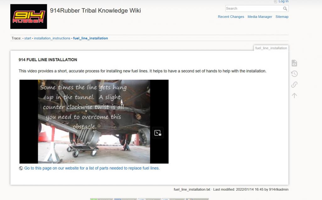 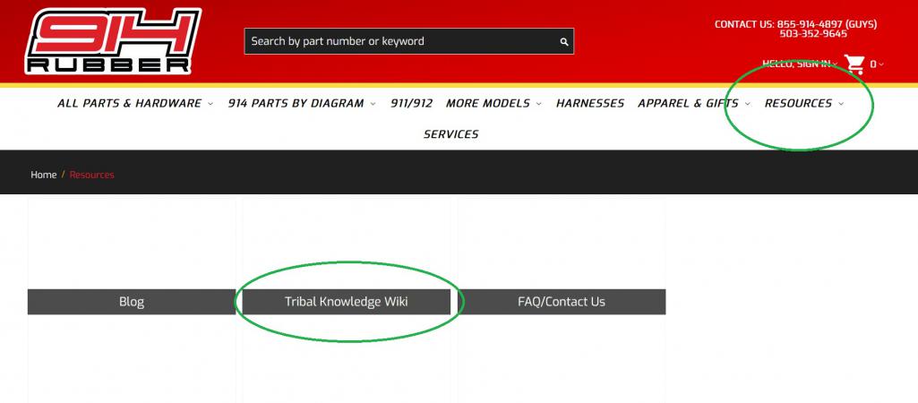
|
|
|
|
| DennisV |
May 20 2023, 08:39 AM
Post
#18
|
|
Member Group: Members Posts: 468 Joined: 8-August 20 From: Santa Rosa, CA Member No.: 24,575 Region Association: Northern California |
QUOTE(shredtherad @ May 18 2023, 10:30 AM) Cool, I got a couple already! I planned a little bit. Did you get it complete? How did it go? What were the gotchas? I'm going to do this on our 914-6 next weekend and have a small window to get it done. Not sure how different the 4 and the 6 are other than the lines themselves. |
|
|
|
| shredtherad |
May 22 2023, 08:07 AM
Post
#19
|
|
Member Group: Members Posts: 86 Joined: 17-May 22 From: Longmont, Colorado Member No.: 26,559 Region Association: Rocky Mountains |
QUOTE(Mikey914 @ May 18 2023, 04:49 PM) We have a "Tribal Wiki" that is accessed from the resources tab on the front page. https://914rubber-tk.com/doku.php?id=fuel_line_installation Cool, I will check this out! Thanks. |
|
|
|
| shredtherad |
May 22 2023, 08:08 AM
Post
#20
|
|
Member Group: Members Posts: 86 Joined: 17-May 22 From: Longmont, Colorado Member No.: 26,559 Region Association: Rocky Mountains |
QUOTE(DennisV @ May 20 2023, 08:39 AM) QUOTE(shredtherad @ May 18 2023, 10:30 AM) Cool, I got a couple already! I planned a little bit. Did you get it complete? How did it go? What were the gotchas? I'm going to do this on our 914-6 next weekend and have a small window to get it done. Not sure how different the 4 and the 6 are other than the lines themselves. I have it mostly sorted out and will button it up today. I will share my thoughts after. |
|
|
|
|
1 User(s) are reading this topic (1 Guests and 0 Anonymous Users)
0 Members:

|
Lo-Fi Version | Time is now: 3rd May 2024 - 05:39 AM |
Invision Power Board
v9.1.4 © 2024 IPS, Inc.