|
|
|
Porsche, and the Porsche crest are registered trademarks of Dr. Ing. h.c. F. Porsche AG.
This site is not affiliated with Porsche in any way. Its only purpose is to provide an online forum for car enthusiasts. All other trademarks are property of their respective owners. |
|
|


| Spoke |
 Dec 3 2023, 06:10 PM Dec 3 2023, 06:10 PM
Post
#41
|
|
Jerry  Group: Members Posts: 7,370 Joined: 29-October 04 From: Allentown, PA Member No.: 3,031 Region Association: None |
There has been some interest in a module that would flash the front sidemarker with the turnsignal. The rear running/brake/turnsignal board I did for the 356 using the front turnsignal bucket from a 914 uses the same function to flash the running or brake light when the turnsignal comes on.
The flashing circuit was lifted from the 356 board and placed on this board with some modification. The board will be about 1.6in x 1in and will be enclosed in a small plastic box. The module will replace the wires which go from the front trunk into the rubber wire channel to the sidemarker and turnsignal. Basically the wires to the turnsignal and sidemarker will be pulled out of the rubber channel and connected to the module. The module will have wires that will be fished into the rubber channel and connected to the sidemarker and turnsignal just like the OEM wiring. The OEM wiring will remain intact keeping with my goal of no cutting/screwing/gluing plug-and-play installation. @Cairo94507 Attached thumbnail(s) 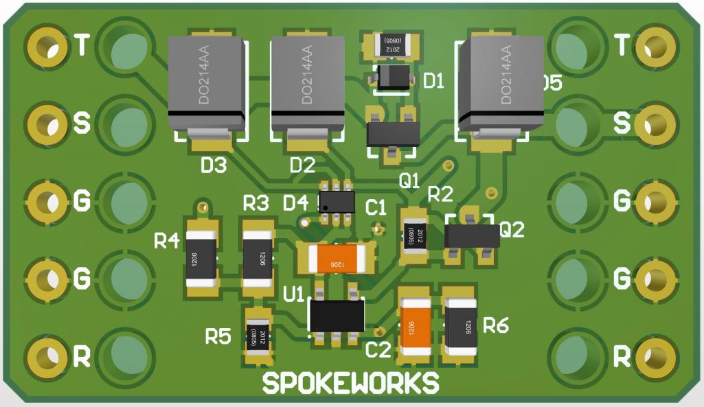
|
   |

 
|
Posts in this topic
 Spoke Front Sidemarker Flasher Module Dec 3 2023, 06:10 PM
 Long_ago Yes please.
HB Dec 3 2023, 06:18 PM FlacaProductions Interested. Dec 3 2023, 06:40 PM 914werke :cheer: Dec 3 2023, 06:59 PM burton73 Great idea to be safe.
Bob B Dec 3 2023, 07:20 PM 56kabrio
There has been some interest in a module that wou... Dec 3 2023, 09:26 PM second wind This would be a very nice safety modification....p... Dec 3 2023, 11:58 PM Cairo94507 Of course I want a set. :). Thank you Jerry for so... Dec 4 2023, 08:30 AM sb914 Great job once again! Dec 4 2023, 10:10 AM 914werke to clarify will this new board cause the sidemarke... Dec 4 2023, 10:51 AM
Long_ago Yes please.
HB Dec 3 2023, 06:18 PM FlacaProductions Interested. Dec 3 2023, 06:40 PM 914werke :cheer: Dec 3 2023, 06:59 PM burton73 Great idea to be safe.
Bob B Dec 3 2023, 07:20 PM 56kabrio
There has been some interest in a module that wou... Dec 3 2023, 09:26 PM second wind This would be a very nice safety modification....p... Dec 3 2023, 11:58 PM Cairo94507 Of course I want a set. :). Thank you Jerry for so... Dec 4 2023, 08:30 AM sb914 Great job once again! Dec 4 2023, 10:10 AM 914werke to clarify will this new board cause the sidemarke... Dec 4 2023, 10:51 AM
 Spoke
to clarify will this new board cause the sidemark... Dec 4 2023, 11:04 AM Root_Werks What a neat idea! Almost wish I still had side... Dec 4 2023, 04:38 PM DRPHIL914
There has been some interest in a module that wou... Dec 5 2023, 12:27 PM Spoke
There has been some interest in a module that wo... Dec 5 2023, 04:10 PM Chris H. I'll take a set. Dec 5 2023, 12:39 PM Spoke BTW looks like I f'ed up the schematic on the ... Dec 5 2023, 04:21 PM majkos1 :popcorn: Dec 6 2023, 08:22 AM majkos1 :popcorn: Dec 6 2023, 08:23 AM anderssj Yes please. Dec 6 2023, 06:14 PM StratPlayer In, indeed Dec 6 2023, 08:26 PM second wind You build ....I buy !!!!
gg Dec 6 2023, 11:24 PM Spoke A little Christmas present a bit early. Gotta do s... Dec 16 2023, 02:23 AM Cairo94507 Very cool; can't wait to get them. Thanks for ... Dec 16 2023, 07:04 AM Spoke Assembled the first set of boards. They seem to wo... Dec 22 2023, 07:27 PM Jack Standz OK, looks great!
We will take one set when ... Dec 23 2023, 10:56 AM Spoke OK time to install the flasher module on my 914. M... Dec 24 2023, 03:02 PM Spoke Pulled the sidemarker wires off the socket ok. But... Dec 24 2023, 03:06 PM Spoke All the wires have been pulled out of the conduit.... Dec 24 2023, 03:11 PM Spoke This is the power spade pulled off of the sidemark... Dec 24 2023, 03:14 PM Spoke This is the assembly for one side. The module has ... Dec 24 2023, 07:48 PM Spoke To pull the wires and spades for the sidemarker th... Dec 24 2023, 07:55 PM Spoke Sidemarker wires pulled through the main conduit.
... Dec 24 2023, 07:59 PM Spoke Wires all connected and tie wrapped. The pigtail w... Dec 24 2023, 08:03 PM Spoke The module in action. When the turnsignals end not... Dec 24 2023, 08:07 PM Cairo94507 Great work Jerry; Merry Christmas. Looking forwar... Dec 25 2023, 08:00 AM Osnabruck914 Not sure why this is being made so complicated. I... Dec 25 2023, 12:32 PM Spoke
Not sure why this is being made so complicated. ... Dec 25 2023, 06:42 PM Osnabruck914
[quote name='Osnabruck914' post='3119885' date='D... Dec 25 2023, 06:56 PM Cairo94507 Going to take a shot at this.... Jerry is making L... Dec 25 2023, 04:13 PM FlacaProductions Maybe this is the procedure in this thread:
https:... Dec 25 2023, 10:03 PM Spoke
Maybe this is the procedure in this thread:
https... Dec 26 2023, 04:18 PM FlacaProductions Interesting and didn't want to rain on your de... Dec 26 2023, 05:05 PM Spoke The driver side installation went very well. Lesso... Jan 1 2024, 02:46 PM fixer34 So I got looking at the diagrams and wondering if ... Jan 3 2024, 09:00 PM Spoke
So I got looking at the diagrams and wondering if... Jan 3 2024, 11:11 PM fixer34
So I got looking at the diagrams and wondering i... Jan 4 2024, 09:42 AM BillC @Spoke -- I love the idea, but have a question ab... Jan 4 2024, 11:42 AM Spoke
@[url=http://www.914world.com/bbs2/index.php?show... Jan 6 2024, 03:11 PM BillC
[quote name='BillC' post='3121791' date='Jan 4 20... Jan 27 2024, 11:04 AM Spoke
Any idea when these new modules will come to mark... Jul 25 2025, 09:46 AM fixer34
[quote name='BillC' post='3125778' date='Jan 27 2... Jul 25 2025, 06:29 PM Spoke I still have a couple 1.5 x2" project boards ... Jul 25 2025, 07:56 PM Spoke
There's an obvious mistake on the circuit. Ca... Aug 4 2025, 11:12 AM fixer34
[b]@[url=http://www.914world.com/bbs2/index.php?s... Jan 6 2024, 06:35 PM Cairo94507 Another way to make our cars a little bit more vis... Jul 25 2025, 09:57 AM Spoke Got the first modules assembled and working.
POX0... Aug 3 2025, 09:56 PM Spoke @Cairo94507
[b]@[url=http://www.914world.com/bbs... Aug 11 2025, 11:08 AM Spoke The installation procedure is:
1) Jack the car up... Aug 11 2025, 11:28 AM Cairo94507 @Spoke - Wow! Thank you Jerry. I look forwa... Aug 12 2025, 05:55 AM saladin @Cairo94507 and [b]@[url=http://www.914world.com... Dec 18 2025, 10:45 PM Cairo94507 I am sorry I have not got to these; I have been bu... Dec 19 2025, 07:42 AM Spoke Bill decided not to do the conversion so @Ron914 ... Dec 19 2025, 08:12 AM Ron914 Hi Jerry , @Spoke
I almost have all the parts ne... Dec 19 2025, 09:42 AM Ron914 I finally had a chance to start the install of Spo... Feb 2 2026, 09:16 PM
Spoke
to clarify will this new board cause the sidemark... Dec 4 2023, 11:04 AM Root_Werks What a neat idea! Almost wish I still had side... Dec 4 2023, 04:38 PM DRPHIL914
There has been some interest in a module that wou... Dec 5 2023, 12:27 PM Spoke
There has been some interest in a module that wo... Dec 5 2023, 04:10 PM Chris H. I'll take a set. Dec 5 2023, 12:39 PM Spoke BTW looks like I f'ed up the schematic on the ... Dec 5 2023, 04:21 PM majkos1 :popcorn: Dec 6 2023, 08:22 AM majkos1 :popcorn: Dec 6 2023, 08:23 AM anderssj Yes please. Dec 6 2023, 06:14 PM StratPlayer In, indeed Dec 6 2023, 08:26 PM second wind You build ....I buy !!!!
gg Dec 6 2023, 11:24 PM Spoke A little Christmas present a bit early. Gotta do s... Dec 16 2023, 02:23 AM Cairo94507 Very cool; can't wait to get them. Thanks for ... Dec 16 2023, 07:04 AM Spoke Assembled the first set of boards. They seem to wo... Dec 22 2023, 07:27 PM Jack Standz OK, looks great!
We will take one set when ... Dec 23 2023, 10:56 AM Spoke OK time to install the flasher module on my 914. M... Dec 24 2023, 03:02 PM Spoke Pulled the sidemarker wires off the socket ok. But... Dec 24 2023, 03:06 PM Spoke All the wires have been pulled out of the conduit.... Dec 24 2023, 03:11 PM Spoke This is the power spade pulled off of the sidemark... Dec 24 2023, 03:14 PM Spoke This is the assembly for one side. The module has ... Dec 24 2023, 07:48 PM Spoke To pull the wires and spades for the sidemarker th... Dec 24 2023, 07:55 PM Spoke Sidemarker wires pulled through the main conduit.
... Dec 24 2023, 07:59 PM Spoke Wires all connected and tie wrapped. The pigtail w... Dec 24 2023, 08:03 PM Spoke The module in action. When the turnsignals end not... Dec 24 2023, 08:07 PM Cairo94507 Great work Jerry; Merry Christmas. Looking forwar... Dec 25 2023, 08:00 AM Osnabruck914 Not sure why this is being made so complicated. I... Dec 25 2023, 12:32 PM Spoke
Not sure why this is being made so complicated. ... Dec 25 2023, 06:42 PM Osnabruck914
[quote name='Osnabruck914' post='3119885' date='D... Dec 25 2023, 06:56 PM Cairo94507 Going to take a shot at this.... Jerry is making L... Dec 25 2023, 04:13 PM FlacaProductions Maybe this is the procedure in this thread:
https:... Dec 25 2023, 10:03 PM Spoke
Maybe this is the procedure in this thread:
https... Dec 26 2023, 04:18 PM FlacaProductions Interesting and didn't want to rain on your de... Dec 26 2023, 05:05 PM Spoke The driver side installation went very well. Lesso... Jan 1 2024, 02:46 PM fixer34 So I got looking at the diagrams and wondering if ... Jan 3 2024, 09:00 PM Spoke
So I got looking at the diagrams and wondering if... Jan 3 2024, 11:11 PM fixer34
So I got looking at the diagrams and wondering i... Jan 4 2024, 09:42 AM BillC @Spoke -- I love the idea, but have a question ab... Jan 4 2024, 11:42 AM Spoke
@[url=http://www.914world.com/bbs2/index.php?show... Jan 6 2024, 03:11 PM BillC
[quote name='BillC' post='3121791' date='Jan 4 20... Jan 27 2024, 11:04 AM Spoke
Any idea when these new modules will come to mark... Jul 25 2025, 09:46 AM fixer34
[quote name='BillC' post='3125778' date='Jan 27 2... Jul 25 2025, 06:29 PM Spoke I still have a couple 1.5 x2" project boards ... Jul 25 2025, 07:56 PM Spoke
There's an obvious mistake on the circuit. Ca... Aug 4 2025, 11:12 AM fixer34
[b]@[url=http://www.914world.com/bbs2/index.php?s... Jan 6 2024, 06:35 PM Cairo94507 Another way to make our cars a little bit more vis... Jul 25 2025, 09:57 AM Spoke Got the first modules assembled and working.
POX0... Aug 3 2025, 09:56 PM Spoke @Cairo94507
[b]@[url=http://www.914world.com/bbs... Aug 11 2025, 11:08 AM Spoke The installation procedure is:
1) Jack the car up... Aug 11 2025, 11:28 AM Cairo94507 @Spoke - Wow! Thank you Jerry. I look forwa... Aug 12 2025, 05:55 AM saladin @Cairo94507 and [b]@[url=http://www.914world.com... Dec 18 2025, 10:45 PM Cairo94507 I am sorry I have not got to these; I have been bu... Dec 19 2025, 07:42 AM Spoke Bill decided not to do the conversion so @Ron914 ... Dec 19 2025, 08:12 AM Ron914 Hi Jerry , @Spoke
I almost have all the parts ne... Dec 19 2025, 09:42 AM Ron914 I finally had a chance to start the install of Spo... Feb 2 2026, 09:16 PM  |
1 User(s) are reading this topic (1 Guests and 0 Anonymous Users)
0 Members:

|
Lo-Fi Version | Time is now: 2nd April 2026 - 05:00 PM |
Invision Power Board
v9.1.4 © 2026 IPS, Inc.