|
|
|
Porsche, and the Porsche crest are registered trademarks of Dr. Ing. h.c. F. Porsche AG.
This site is not affiliated with Porsche in any way. Its only purpose is to provide an online forum for car enthusiasts. All other trademarks are property of their respective owners. |
|
|


| Dr. Roger |
 Aug 19 2005, 03:47 PM Aug 19 2005, 03:47 PM
Post
#1
|
|
A bat out of hell.  Group: Members Posts: 3,944 Joined: 31-January 05 From: Hercules, California Member No.: 3,533 Region Association: Northern California |
I'm getting rid of that POS board and doing my own thing there.
I'm sure it's been posted before what all 16 or 18 wires are going into the relay board. I searched for relay board pins relay board, which brought a zillion responses relay, the same. pin layout by any chance does anyone know where that msg thread is? =-) Much thanks, Roger |
   |

 
|
  |
Replies(1 - 9)
| lapuwali |
Aug 19 2005, 04:18 PM
Post
#2
|
|
Not another one! Group: Benefactors Posts: 4,526 Joined: 1-March 04 From: San Mateo, CA Member No.: 1,743 |
See my blog...
|
|
|
|
| Cap'n Krusty |
Aug 19 2005, 04:27 PM
Post
#3
|
|
Cap'n Krusty Group: Members Posts: 10,794 Joined: 24-June 04 From: Santa Maria, CA Member No.: 2,246 Region Association: Central California |
|
|
|
|
| Mueller |
Aug 19 2005, 04:31 PM
Post
#4
|
|
914 Freak! Group: Members Posts: 17,146 Joined: 4-January 03 From: Antioch, CA Member No.: 87 Region Association: None |
I cheated and re-used the male pins from the relay board and soldered them to the female pins from one of the connectors:
Pins removed from relay board: Attached image(s) 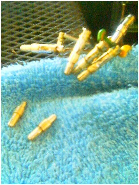
|
|
|
|
| Mueller |
Aug 19 2005, 04:32 PM
Post
#5
|
|
914 Freak! Group: Members Posts: 17,146 Joined: 4-January 03 From: Antioch, CA Member No.: 87 Region Association: None |
assembled and in use:
Attached image(s) 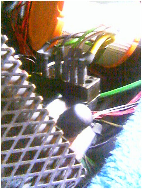
|
|
|
|
| john rogers |
Aug 19 2005, 04:43 PM
Post
#6
|
|
Senior Member Group: Members Posts: 1,525 Joined: 4-March 03 From: Chula Vista CA Member No.: 391 |
What I have seen on several cars and I plan to do one of these days is to buy one of those multi pin mil spec connectors or two and replace the board in my six conversion race car. The voltage regulator is internal to the alt and it would make that corner look much nicer. In the case of a more stock sort of setup the relays and fuses can be added in-line with connectors that are available at any good electronics store or Mouser.com.
|
|
|
|
| lapuwali |
Aug 19 2005, 04:50 PM
Post
#7
|
|
Not another one! Group: Benefactors Posts: 4,526 Joined: 1-March 04 From: San Mateo, CA Member No.: 1,743 |
Have you priced those MIL-SPEC connectors? Two shells (male and female) and pins can easily add up to over $100. Look at rs-autosport.com or waytekwire.com for sealed Weatherpack connectors. $20 should buy you all you require.
|
|
|
|
| Dr. Roger |
Aug 19 2005, 05:08 PM
Post
#8
|
|
A bat out of hell. Group: Members Posts: 3,944 Joined: 31-January 05 From: Hercules, California Member No.: 3,533 Region Association: Northern California |
Thank you James, Mike, John, and Capn'. =-)
Gotta get back to the garage for an evening finale of productivity.... (IMG:http://www.914world.com/bbs2/html/emoticons/laugh.gif) (IMG:http://www.914world.com/bbs2/html/emoticons/smile.gif) |
|
|
|
| scruz914 |
Aug 19 2005, 07:23 PM
Post
#9
|
|
Senior Member Group: Members Posts: 815 Joined: 26-February 04 From: Santa Cruz, CA Member No.: 1,724 |
This is for a '73 board. May help you.
-Jeff Attached thumbnail(s) 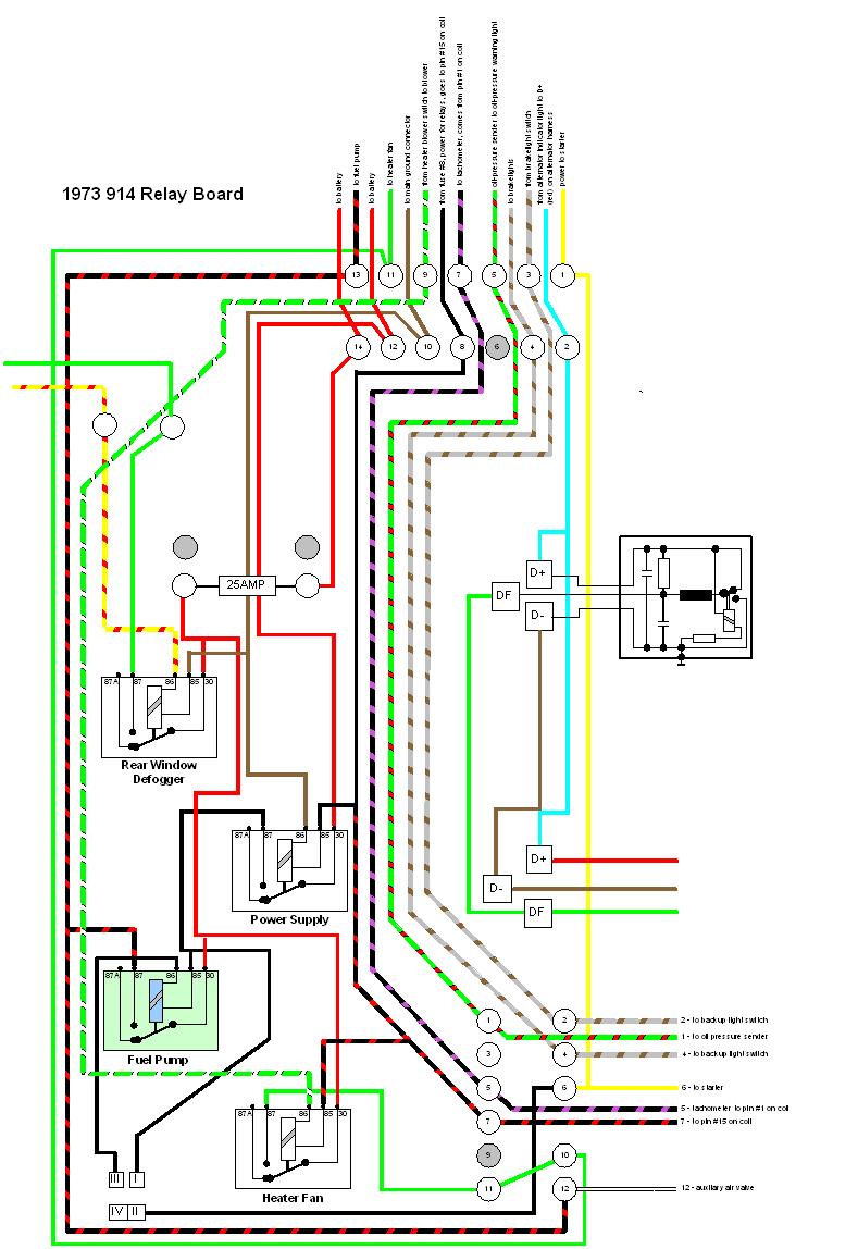
|
|
|
|
| SGB |
Aug 19 2005, 08:08 PM
Post
#10
|
|
just visiting Group: Members Posts: 4,086 Joined: 8-March 03 From: Huntsville, AL Member No.: 404 Region Association: South East States |
Jeff -
that is a really nice diagram. I've rebuilt my relay board, now, and kinda wondered about it then since it looked kinda convoluted. Why would the designers make such strange setup- one relay feeds the other relays. Why? And some relays are fused like the rw defroster, but others supplied by the power relay. Seems awfully unnecessary. |
|
|
|
|
1 User(s) are reading this topic (1 Guests and 0 Anonymous Users)
0 Members:

|
Lo-Fi Version | Time is now: 24th May 2024 - 07:45 AM |
Invision Power Board
v9.1.4 © 2024 IPS, Inc.