|
|
|
Porsche, and the Porsche crest are registered trademarks of Dr. Ing. h.c. F. Porsche AG.
This site is not affiliated with Porsche in any way. Its only purpose is to provide an online forum for car enthusiasts. All other trademarks are property of their respective owners. |
|
|

  |

| Ron914 |
 Jun 30 2026, 01:43 PM Jun 30 2026, 01:43 PM
Post
#101
|
|
Senior Member  Group: Members Posts: 548 Joined: 19-April 22 From: Huntington Beach,Ca Member No.: 26,487 Region Association: Southern California |
QUOTE(930cabman @ Jun 30 2026, 01:53 PM)  It's possible it fixed itself, those are the best ones (IMG:style_emoticons/default/piratenanner.gif) (IMG:style_emoticons/default/piratenanner.gif) If only I could be so lucky. |
   |

 
|
| Ron914 |
Jun 30 2026, 02:07 PM
Post
#102
|
|
Senior Member Group: Members Posts: 548 Joined: 19-April 22 From: Huntington Beach,Ca Member No.: 26,487 Region Association: Southern California |
QUOTE(Superhawk996 @ Jun 30 2026, 01:48 PM) (IMG:style_emoticons/default/smilie_pokal.gif) Now let’s figure out that Dakota CHT I don’t have one but lots of others here have them and can chime in with their set up. Reading manual it seems F/C default is controlled by a one time set up. In turn controlled by temporarily shorting the thermocouple inputs? How is your CHT set up? Did you do the initial set up? Have you ever tested a calibration point (boiling water) . Did you change any of the ring terminals anywhere in the sensor to gauge connection path? I’m not buying that your heads are only 100 degrees even if that is reading Celsius. Their manual mentions they limit low end temp to 90-150F. Does your gauge ever read higher than this range? I don't buy the temperature of my heads either ? I sent the gauge back under warranty and explained the problem to the THD guy . Here is the response to me and the instructions to set up. I have probably reset this 40 times , so many that I put in a DPDT toggle switch to make it easier. As you can see in the manual factory default is F /450F hi warning temp. I did order the wrong ring terminal sensor 1/2". I have not messed with any of the connection ring terminals on the wire from the sensor to the gauge although they also told me if I wanted to shorten it was ok just don't mess with the sensor wire (I did not) . I did purchase the 14' wire with 1/2 ring . I might try calling one more time and push the ongoing warranty issue and send a video of the gauge being set and under driving conditions . 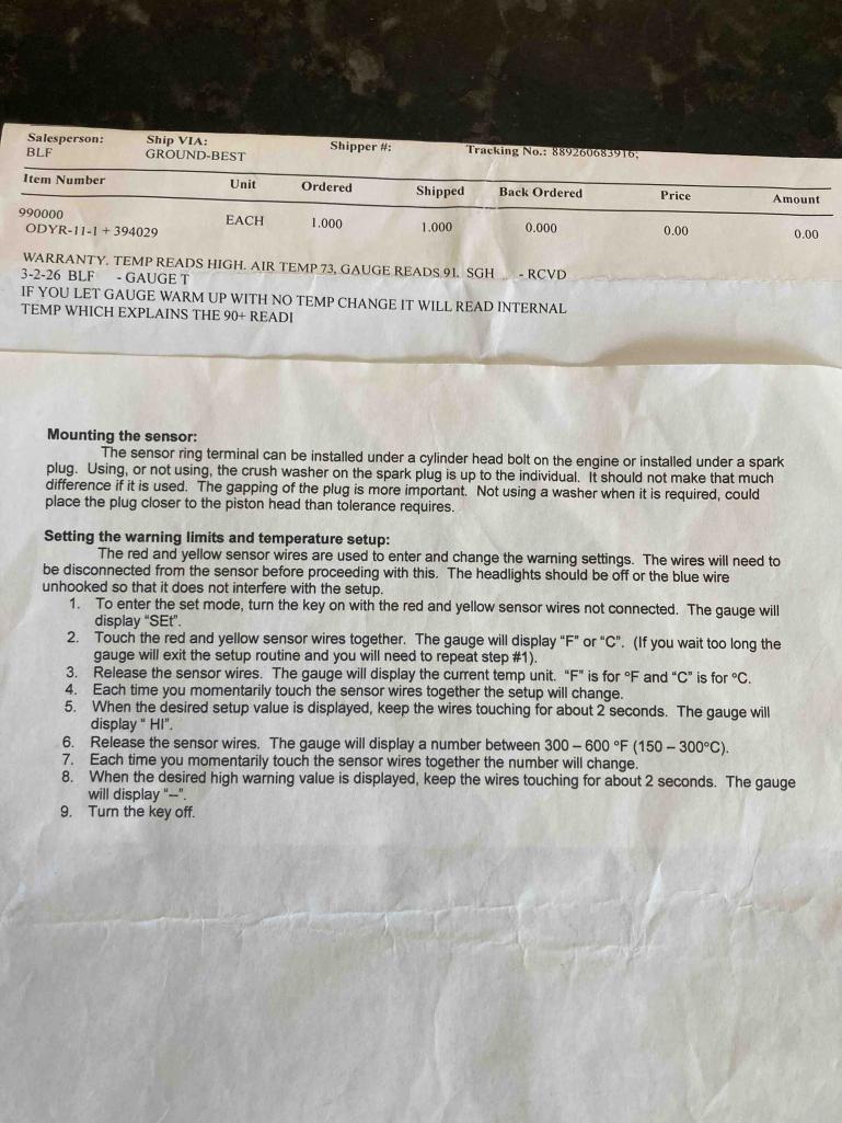 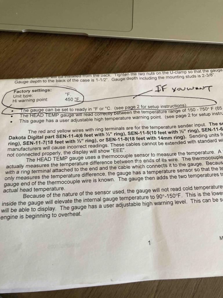 |
|
|
|
| Superhawk996 |
Jun 30 2026, 02:37 PM
Post
#103
|
|
914 Guru Group: Members Posts: 7,935 Joined: 25-August 18 From: Woods of N. Idaho Member No.: 22,428 Region Association: Galt's Gulch |
So where is this switch located?
You cannot have any sort of DPDT switch anywhere between the gauge and the sensor. |
|
|
|
| FlacaProductions |
Jun 30 2026, 02:37 PM
Post
#104
|
|
Advanced Member Group: Members Posts: 2,245 Joined: 24-November 17 From: LA Member No.: 21,628 Region Association: Southern California |
Apologies for the rudimentary drawing but it was the quickest way for me to do it.
Make sure you have the yellow nut/bolt wiring connections for the Dakota as shown. I initially installed mine connected "long" to "long" and "short" to "short" and was getting odd readings like yours. I had to pull the wiring back thru the firewall and flip it end-to-end to get the connections correct. Hope this makes sense - it should if you are looking at the Dakota wiring. 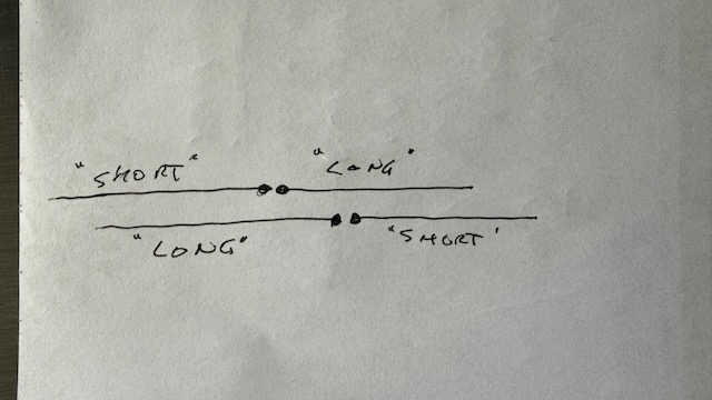 |
|
|
|
| Ron914 |
Jun 30 2026, 02:53 PM
Post
#105
|
|
Senior Member Group: Members Posts: 548 Joined: 19-April 22 From: Huntington Beach,Ca Member No.: 26,487 Region Association: Southern California |
QUOTE(FlacaProductions @ Jun 30 2026, 03:37 PM) Apologies for the rudimentary drawing but it was the quickest way for me to do it. Make sure you have the yellow nut/bolt wiring connections for the Dakota as shown. I initially installed mine connected "long" to "long" and "short" to "short" and was getting odd readings like yours. I had to pull the wiring back thru the firewall and flip it end-to-end to get the connections correct. Hope this makes sense - it should if you are looking at the Dakota wiring. Intertesting Brian, The wires are red and yellow I would think you would connect red to red and yellow to yellow when I looked at the connections on the back of my toggle switch I can tell the red wires are longer than the yellow ones . If I am understanding you I should connect the short yellow to the long red for each lead . Did you have the same issue I have with setting the value to F along with low readings? 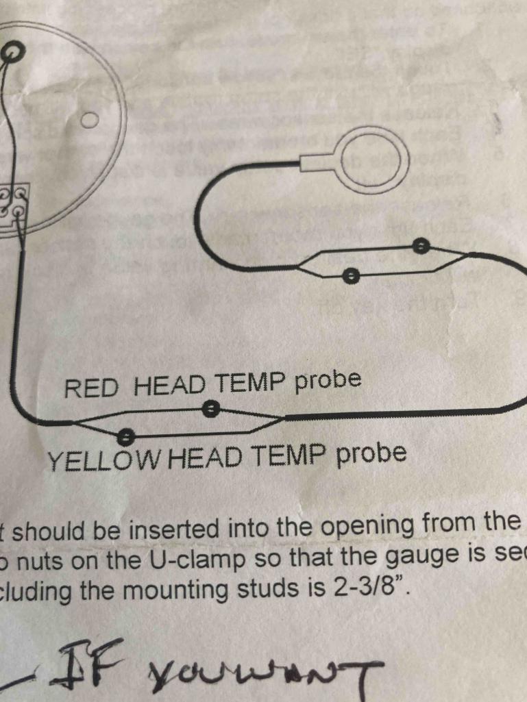  |
|
|
|
| Ron914 |
Jun 30 2026, 02:58 PM
Post
#106
|
|
Senior Member Group: Members Posts: 548 Joined: 19-April 22 From: Huntington Beach,Ca Member No.: 26,487 Region Association: Southern California |
QUOTE(Superhawk996 @ Jun 30 2026, 03:37 PM) So where is this switch located? You cannot have any sort of DPDT switch anywhere between the gauge and the sensor. The wires are between the gauge and sensor .It's a PITA to have to keep pulling apart the little screws /washers and nuts . Hmmm 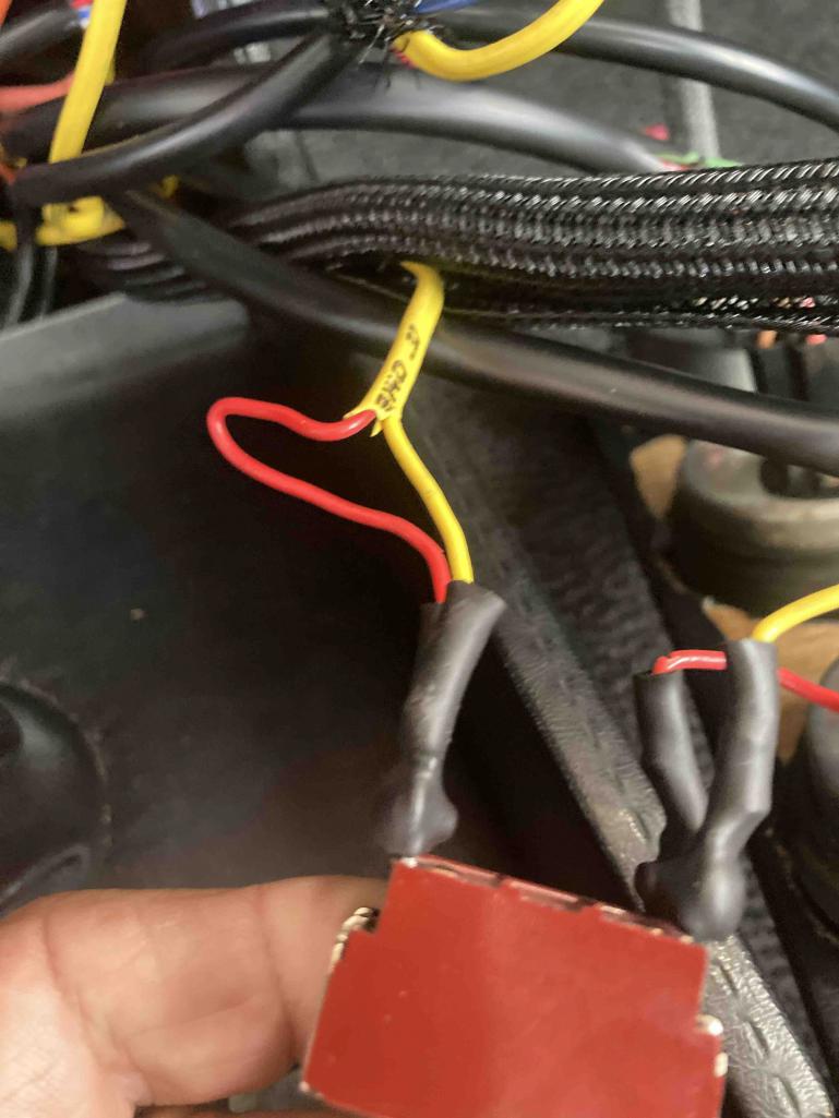 |
|
|
|
| FlacaProductions |
Jun 30 2026, 03:00 PM
Post
#107
|
|
Advanced Member Group: Members Posts: 2,245 Joined: 24-November 17 From: LA Member No.: 21,628 Region Association: Southern California |
We may be onto something here.
I follow you on colors and maybe that's what i did, initially - but when i got strange readings (much like yours) I re-did things and all is well. Give it a whirl - can't break it any more... also - toggle switch? could that be messing with things? Take that out of line, do the connections as i drew (and like the illustration in the instructions) and see what happens. I know that on a cold start when I turn the key on, (and let the fuel pump run...) i get a reading that is very close to ambient. |
|
|
|
| Ron914 |
Jun 30 2026, 03:06 PM
Post
#108
|
|
Senior Member Group: Members Posts: 548 Joined: 19-April 22 From: Huntington Beach,Ca Member No.: 26,487 Region Association: Southern California |
QUOTE(FlacaProductions @ Jun 30 2026, 04:00 PM) We may be onto something here. I follow you on colors and maybe that's what i did, initially - but when i got strange readings (much like yours) I re-did things and all is well. Give it a whirl - can't break it any more... also - toggle switch? could that be messing with things? Take that out of line, do the connections as i drew (and like the illustration in the instructions) and see what happens. I know that on a cold start when I turn the key on, (and let the fuel pump run...) i get a reading that is very close to ambient. I also get a reading corresponding to ambient but I have nothing to lose except those littles screws and washers they give you ,can't seem to find them now . I will remove the toggle switch from the circuit later and report back . |
|
|
|
| Ron914 |
Jun 30 2026, 03:07 PM
Post
#109
|
|
Senior Member Group: Members Posts: 548 Joined: 19-April 22 From: Huntington Beach,Ca Member No.: 26,487 Region Association: Southern California |
QUOTE(Ron914 @ Jun 30 2026, 03:58 PM) QUOTE(Superhawk996 @ Jun 30 2026, 03:37 PM) So where is this switch located? You cannot have any sort of DPDT switch anywhere between the gauge and the sensor. The wires are between the gauge and sensor .It's a PITA to have to keep pulling apart the little screws /washers and nuts . Hmmm I will say that in the beginning I did not have a toggle switch in the circuit and had the same problem . |
|
|
|
| Superhawk996 |
Jun 30 2026, 03:20 PM
Post
#110
|
|
914 Guru Group: Members Posts: 7,935 Joined: 25-August 18 From: Woods of N. Idaho Member No.: 22,428 Region Association: Galt's Gulch |
You cannot have the toggle in there.
I’m not sure how to explain this succinctly. Thermocouple wire is made of two very special alloys. It needs to be consistent alloy from gauge to sensor. Even the small ring terminal they provide installed onto the wires to make the connections will be special alloy and AREN’T just normal copper/tin ring terminals. By putting the switch in line you’re introducing copper, tin, and other alloys into the circuit and this will (IMG:style_emoticons/default/sheeplove.gif) things up big time. Remove the switch. Follow the set up directions exactly to get your default to F. Set the high limit to 400. |
|
|
|
| Superhawk996 |
Jun 30 2026, 03:31 PM
Post
#111
|
|
914 Guru Group: Members Posts: 7,935 Joined: 25-August 18 From: Woods of N. Idaho Member No.: 22,428 Region Association: Galt's Gulch |
Keep red to red
Yellow to yellow |
|
|
|
| emerygt350 |
Jun 30 2026, 04:18 PM
Post
#112
|
|
Advanced Member Group: Members Posts: 3,666 Joined: 20-July 21 From: Upstate, NY Member No.: 25,740 Region Association: North East States |
It's supposed to be long to short and short to long. Who cares what color they are. My gauge was hooked up as the instructions describe and it has worked flawlessly
And excellent news about the heat. I would take another peak at the flap though and see how that is sitting after the twisting. |
|
|
|
| Blue Lightning |
Jun 30 2026, 04:21 PM
Post
#113
|
|
Member Group: Members Posts: 78 Joined: 7-December 23 From: Atlanta, GA, USA Member No.: 27,780 Region Association: South East States |
QUOTE(930cabman @ Jun 5 2026, 11:07 AM) Can you remove the intake and items and remove the upper tins? Secure the flaps in the open position, ditch the stat, reassemble, drive the car I recently removed the passenger-side upper tins with the engine in the car for exactly this same problem (but didn't secure the flaps, as such). It is doable, and I think less work than dropping the engine and taking the fan and fan shroud off. Be prepared to remove the intake runners on the passenger side to do this, and the associated work to reseal them. |
|
|
|
| Ishley |
Jun 30 2026, 04:32 PM
Post
#114
|
|
Member Group: Members Posts: 358 Joined: 4-October 21 From: Clarendon Hills Il Member No.: 25,957 Region Association: Upper MidWest |
I just finished installing a Dakota head temp sensor. I did not like the connectors and cut them off and installed thermo coupler plugs. Wire it Yellow to yellow and red to red. On type k wiring the red is the negative. You have to carefully cut and trim the ends to insert into the correct side (+ or -) on the plugs. At the spark plug connection special considerations are needed. The bare looking wires are coated. If you look carefully you can see where it has heavy coating as you move towards the ring. You need to make sure that the wires above that are not touching the each other as they go into the coupler. I also used sand paper to make sure the ends going in the plug were not coated. It’s fidgety for sure. Just go slow and get the connections perfect. If it doesn’t work flip the wires on the spark plug coupler. If you have a switch in this line you need to replace it with a coupler. 2 couplers are $8 on Amazon.
Another issue I faced was the grounds. I originally shared the ground with other gauges. This caused issues with the reading. You have to have the black wire to ground and the gauge via the top screw on the back of the gauge grounded. I ran them to a separate good ground and it started reading correctly. I checked my gauge with one of those instant read meat thermometers and the gauge was +2 degrees F. Attached image(s) 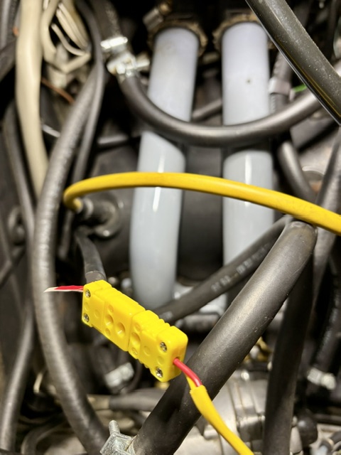
|
|
|
|
| Ron914 |
Jul 1 2026, 10:56 AM
Post
#115
|
|
Senior Member Group: Members Posts: 548 Joined: 19-April 22 From: Huntington Beach,Ca Member No.: 26,487 Region Association: Southern California |
QUOTE(emerygt350 @ Jun 30 2026, 05:18 PM) It's supposed to be long to short and short to long. Who cares what color they are. My gauge was hooked up as the instructions describe and it has worked flawlessly And excellent news about the heat. I would take another peak at the flap though and see how that is sitting after the twisting. I will try this today and post my results . Thanks Dan |
|
|
|
| Ron914 |
Jul 1 2026, 10:57 AM
Post
#116
|
|
Senior Member Group: Members Posts: 548 Joined: 19-April 22 From: Huntington Beach,Ca Member No.: 26,487 Region Association: Southern California |
QUOTE(Ishley @ Jun 30 2026, 05:32 PM) I just finished installing a Dakota head temp sensor. I did not like the connectors and cut them off and installed thermo coupler plugs. Wire it Yellow to yellow and red to red. On type k wiring the red is the negative. You have to carefully cut and trim the ends to insert into the correct side (+ or -) on the plugs. At the spark plug connection special considerations are needed. The bare looking wires are coated. If you look carefully you can see where it has heavy coating as you move towards the ring. You need to make sure that the wires above that are not touching the each other as they go into the coupler. I also used sand paper to make sure the ends going in the plug were not coated. It’s fidgety for sure. Just go slow and get the connections perfect. If it doesn’t work flip the wires on the spark plug coupler. If you have a switch in this line you need to replace it with a coupler. 2 couplers are $8 on Amazon. Another issue I faced was the grounds. I originally shared the ground with other gauges. This caused issues with the reading. You have to have the black wire to ground and the gauge via the top screw on the back of the gauge grounded. I ran them to a separate good ground and it started reading correctly. I checked my gauge with one of those instant read meat thermometers and the gauge was +2 degrees F. I appreciated the comments . I will look into those plugs . I do have a good ground at the gauge so I just need to correct the wiring , I hope . Thanks Ron |
|
|
|
| Ron914 |
Jul 1 2026, 01:51 PM
Post
#117
|
|
Senior Member Group: Members Posts: 548 Joined: 19-April 22 From: Huntington Beach,Ca Member No.: 26,487 Region Association: Southern California |
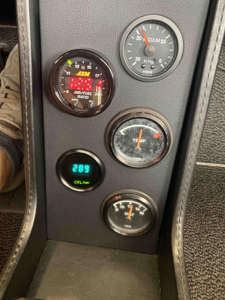  Well looks like you all were correct .The wires were hooked up wrong on the CHT . I corrected the wiring and everything is reading as it should in F now .Took the car for a 50 minute drive ,even got on the freeway for a few miles . My car is finally a driver (IMG:style_emoticons/default/piratenanner.gif) Thank you to everyone who has offered me advice and guidance . I could not have completed this project without the help of the 914 Community . I still have to get the flap corrected but for now I think I am getting sufficient cooling . I also need to start a new challenge of dialing in my MPS but I must say the car is running fairly strong . Time to close this chapter and move on to the next chapter. Thank you Ron |
|
|
|
| FlacaProductions |
Jul 1 2026, 02:18 PM
Post
#118
|
|
Advanced Member Group: Members Posts: 2,245 Joined: 24-November 17 From: LA Member No.: 21,628 Region Association: Southern California |
EXCELLENT!! Good work staying with it.
|
|
|
|
| Superhawk996 |
Jul 1 2026, 02:43 PM
Post
#119
|
|
914 Guru Group: Members Posts: 7,935 Joined: 25-August 18 From: Woods of N. Idaho Member No.: 22,428 Region Association: Galt's Gulch |
(IMG:style_emoticons/default/smilie_pokal.gif) good job seeing it through.
So here’s what you can expect. Oil is going to run hot due to the flap position. You are losing a lot of airflow across the oil cooler. Don’t even sweat oil temps until you get up toward 250F. Remember oil temps lag head temps by a huge margin. Heads will run slightly hotter due to flap position but it seems like you’re probably 80% to of the way to the normal full cooling position. Just keep an an eye on the CHT has your highest priority. You’ll be fine unless you’re driving in really hot ambients or with lots of load (steep extended grades) on the engine. If things do get hot (400F) downshift - remember the fan is driven off the crankshaft. More RPM = more cooling and it simultaneously reduces engine load. Change oil a little more frequently due to elevated oil temps. Go enjoy driving (IMG:style_emoticons/default/driving.gif) it now that you’re not driving blind to temps. |
|
|
|
| JamesM |
Jul 1 2026, 03:39 PM
Post
#120
|
|
Advanced Member Group: Members Posts: 2,263 Joined: 6-April 06 From: Kearns, UT Member No.: 5,834 Region Association: Intermountain Region |
Glad the "force it" approach was able to get it there. Not ideal but hey, it works!
I suspect something may be bent slightly and that you may still be loosing a bit of cooling air over the cooler as the temps are a touch higher than I would expect but well within what the oil should be able to handle. As for how its running 13.5-13.8 AFR at idle is most likely where its going to be the strongest. If you are seeing anywhere in the 13s full warm I would say you are doing well. 14 while driving, depending on the circumstances, is on the lean side at least from a head temp standpoint. between 14 and 15 is where heads get the hottest. Above or below that range things cool off but a stock d-jet distributor wont allow you to go leaner than 15 properly. Now that you have a working head temp gauge though I would say if it aint broke, dont fix it. ie, if the conditions you are driving under when AFRs are hitting 14 are not creating excessive head temps or drivability issues, I wouldn't touch it. MPS are extremely touchy and if the car is driving fine now you are just as likely to make things worse toying with it. Main thing you want to worry about as far as AFRs go is under load. 14 under heavy throttle is no good, you really want to see mid to high 12s there, generally not much leater than 13.0 |
|
|
|
|
1 User(s) are reading this topic (1 Guests and 0 Anonymous Users)
0 Members:

|
Lo-Fi Version | Time is now: 4th July 2026 - 02:45 AM |
Invision Power Board
v9.1.4 © 2026 IPS, Inc.