|
|
|
Porsche, and the Porsche crest are registered trademarks of Dr. Ing. h.c. F. Porsche AG.
This site is not affiliated with Porsche in any way. Its only purpose is to provide an online forum for car enthusiasts. All other trademarks are property of their respective owners. |
|
|

  |

| billd |
 Sep 16 2005, 08:45 AM Sep 16 2005, 08:45 AM
Post
#1
|
|
Member  Group: Members Posts: 327 Joined: 25-May 05 From: Palo Alto, CA Member No.: 4,145 |
I started out to restore my 73 2.0L to its original D-Jetronic fuel injection. At some point I decided that I while I was working on the fuel system I might as well replace the plastic lines with stainless steel and relocate the pump. Here are some pictures with commentary of the fuel line upgrade.
Overall the fuel line install was fairly easy. It would have been much easier if I hadn't decided to run one solid line from the tank all the way to by the MPS sensor. If I did this over again I would do everything the same except that the solid lines would stop at the right side of the firewall and I'd run hose from there. First, I removed the interior and pulled the fuel tank. Here is a photo of the tank halfway out. The hoses on the tank were long enough that I didn't need to disconnect them through the service hole below the tank. I was able to lift the tank to this position and then disconnect the hoses from above. The new hoses I installed are also long enough to permit access from above. Attached thumbnail(s) 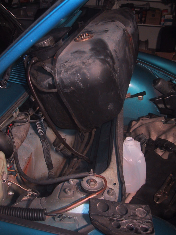
|
   |

 
|
| billd |
Sep 16 2005, 08:52 AM
Post
#2
|
|
Member Group: Members Posts: 327 Joined: 25-May 05 From: Palo Alto, CA Member No.: 4,145 |
Here is a view of the old lines beneath the tank. The old lines come out of a rubber block that connects with the front part of the tunnel. They stick out a few inches.
There is some surface rust under the tank. I cleaned this up with sandpaper and primed it with Zinc-Chromate before installing the new lines. Attached image(s) 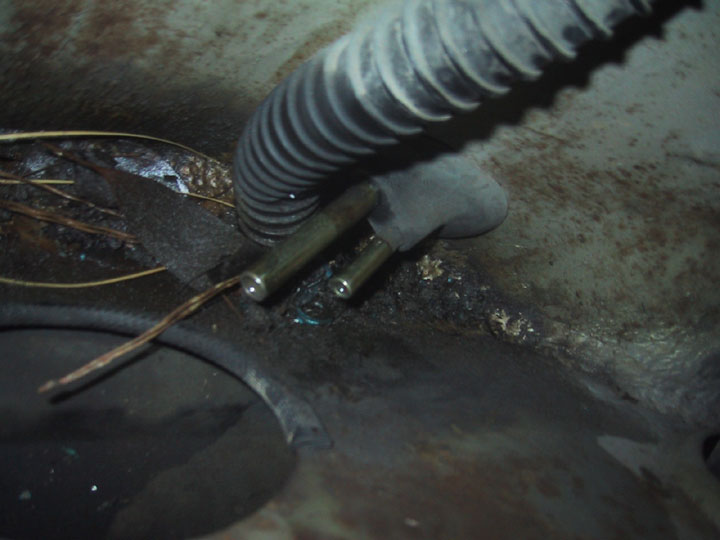
|
|
|
|
| billd |
Sep 16 2005, 08:57 AM
Post
#3
|
|
Member Group: Members Posts: 327 Joined: 25-May 05 From: Palo Alto, CA Member No.: 4,145 |
After the tank was out I pushed the lines back through the block and then went back to the engine compartment, disconnected everything, and pulled. The lines came out easily. I haven't got a clue how you would put plastic lines back in. It would be like pushing a wet noodle up the tunnel.
Here are the lines out of the car. They are steel for the first foot or so and then plastic. The plastic was in pretty good shape but I am still happy I replaced them. There is a ~30 degree bend about xix inches from the end. The new lines go in much easier if you make this bend *before* you stick them down the tunnel. Attached image(s) 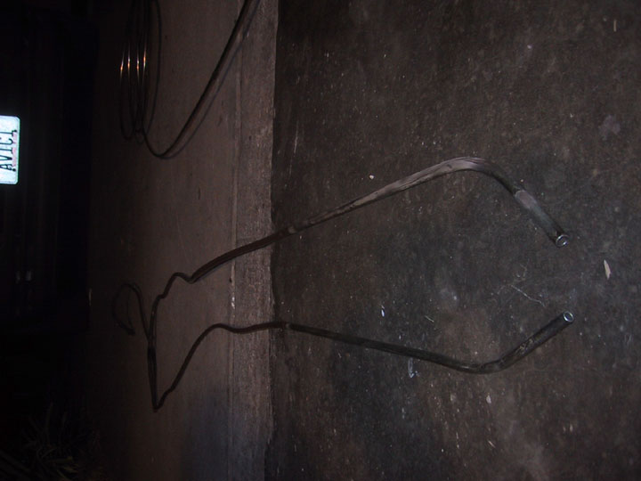
|
|
|
|
| billd |
Sep 16 2005, 08:58 AM
Post
#4
|
|
Member Group: Members Posts: 327 Joined: 25-May 05 From: Palo Alto, CA Member No.: 4,145 |
Another view of the old lines showing the bend near the end.
Attached image(s) 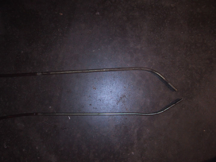
|
|
|
|
| billd |
Sep 16 2005, 09:05 AM
Post
#5
|
|
Member Group: Members Posts: 327 Joined: 25-May 05 From: Palo Alto, CA Member No.: 4,145 |
After the old lines are out its time to put the new lines in. I used 5/16 stainless steel tubing - available from Summit Racing. It comes in a 20 foot length all coiled up. What a pain. I would much rather have started with a straight piece. Also 5/16 inch steel brake line would work fine here. The stainless is nice, but the chance of corrosion in the tunnel is minimal.
I put the 30 degree bend in the line before inserting it in the tunnel. Then I test fit the line to mark where the 90-degree bend (actually about a 110 degree bend followed by a 20 degree bend the other way) at the firewall should be. Then I put the line back through the tunnel. Inserting the lines in the tunnel is fairly easy. You just need to make sure you miss the harness that is right on the other side of the firewall. I reused the original grommets which were in good condition. The small one was a tight fit. The large one needed some RTV to make it snug on the 5/16 line. Here's a picture with one line in and the other on the way. Attached thumbnail(s) 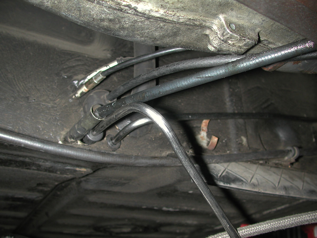
|
|
|
|
| billd |
Sep 16 2005, 09:08 AM
Post
#6
|
|
Member Group: Members Posts: 327 Joined: 25-May 05 From: Palo Alto, CA Member No.: 4,145 |
The lines are run along the firewall and held in place with Adel clamps. I'm probably paranoid, but I don't want them vibrating around and work hardening.
The lines make a 90 degree bend above the heater hose. If I were to do it again I'd stop the hard lines there. Most of the time was spent making the bends after this point and working the lines up through the tin. There is little to be gained by running hard line for the last two feet and that run would be much easier with hose. Attached thumbnail(s) 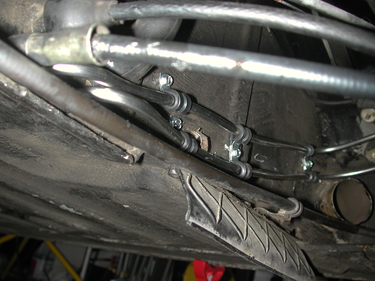
|
|
|
|
| billd |
Sep 16 2005, 09:11 AM
Post
#7
|
|
Member Group: Members Posts: 327 Joined: 25-May 05 From: Palo Alto, CA Member No.: 4,145 |
Here are the lines running along the right side of the engine compartment. The come up through the original grommets, right under the MPS.
|
|
|
|
| billd |
Sep 16 2005, 09:12 AM
Post
#8
|
|
Member Group: Members Posts: 327 Joined: 25-May 05 From: Palo Alto, CA Member No.: 4,145 |
With the picture this time.
Attached thumbnail(s) 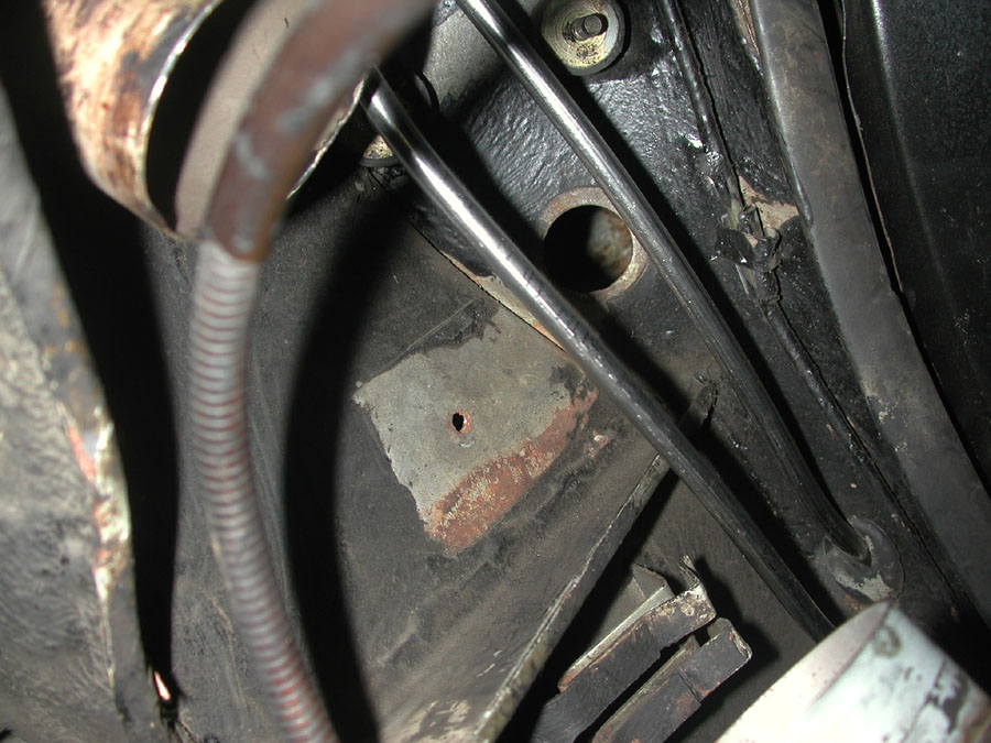
|
|
|
|
| billd |
Sep 16 2005, 09:16 AM
Post
#9
|
|
Member Group: Members Posts: 327 Joined: 25-May 05 From: Palo Alto, CA Member No.: 4,145 |
Meanwhile back under the gas tank, I fabricated a steel bracket to hold the lines. This is probably not needed. In retrospect the rubber block should do an adequate job of keeping the lines from vibrating.
If you do make a bracket, be careful drilling holes here. There is a brake line on the other side of this panel. Attached thumbnail(s) 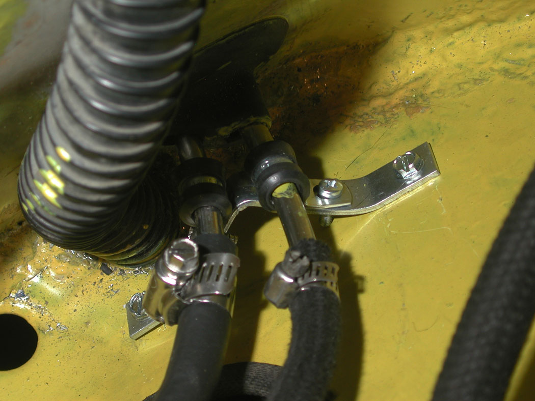
|
|
|
|
| goose2 |
Sep 16 2005, 09:33 AM
Post
#10
|
|
Senior Member Group: Members Posts: 976 Joined: 30-March 05 From: Eugene, Oregon Member No.: 3,847 Region Association: Pacific Northwest |
Good thread, thanks! I'll be doing this soon.
|
|
|
|
| Allan |
Sep 16 2005, 09:38 AM
Post
#11
|
|
Teenerless Weenie Group: Members Posts: 8,373 Joined: 5-July 04 From: Western Mesopotamia Member No.: 2,304 Region Association: Southern California |
You need to replace those clamps with real FI hardware. (IMG:http://www.914world.com/bbs2/html/emoticons/wink.gif)
|
|
|
|
| J P Stein |
Sep 16 2005, 09:50 AM
Post
#12
|
|
Irrelevant old fart Group: Members Posts: 8,797 Joined: 30-December 02 From: Vancouver, WA Member No.: 45 Region Association: None |
How are you clamping the lines in the tunnel?
|
|
|
|
| billd |
Sep 16 2005, 10:01 AM
Post
#13
|
|
Member Group: Members Posts: 327 Joined: 25-May 05 From: Palo Alto, CA Member No.: 4,145 |
The lines are not clamped in the tunnel. They are held at the rear of the tunnel by grommets and at the front by the rubber block. They should be OK without clamps unless some kind of resonance causes them to vibrate in the tunnel.
|
|
|
|
| goose2 |
Sep 16 2005, 10:13 AM
Post
#14
|
||
|
Senior Member Group: Members Posts: 976 Joined: 30-March 05 From: Eugene, Oregon Member No.: 3,847 Region Association: Pacific Northwest |
So what is the issue with the clamps? I've heard many time that you shouldn't use worm screw type clamps on fuel hoses because they may cut into the rubber. Has anyone actually seen this happen or is it another auto myth? I've been using them for 35 years with no problems on low pressure applications like this one. |
||
|
|
|
||
| Allan |
Sep 16 2005, 10:28 AM
Post
#15
|
|
Teenerless Weenie Group: Members Posts: 8,373 Joined: 5-July 04 From: Western Mesopotamia Member No.: 2,304 Region Association: Southern California |
From what I've seen, it's the edges of the clamp. Regular hose clamps have sharp edges where FI clamps are curled up. I have seen old FI hose that was cracked and cut at the clamp.
|
|
|
|
| Grimstead |
Sep 16 2005, 10:40 AM
Post
#16
|
|
Cheaky Monkey Group: Members Posts: 835 Joined: 20-March 05 From: Corona, Ca Member No.: 3,789 Region Association: Southern California |
Great job (IMG:http://www.914world.com/bbs2/html/emoticons/smilie_pokal.gif)
This is one my list before I put the engine back in and your thread is going to help alot. Thanks! (IMG:http://www.914world.com/bbs2/html/emoticons/beer.gif) |
|
|
|
| jsteele22 |
Sep 16 2005, 11:06 AM
Post
#17
|
|
Senior Member Group: Members Posts: 727 Joined: 24-August 05 From: Colorado Springs, CO Member No.: 4,653 |
Great job, thanks for the post. I have a couple of questions.
1) Just to be sure : Did you do the whole job w/ the engine in the car ? 2) When you are pushing the lines in from the rear, how do you manage to get them to come out at the front end of the tunnel ? I haven't done any work in that area, but it sounds like a tough job : like threading a needle from a foot away. 3) What do you use to cut the tubing ? Would a regular (home plumbing style) tubing cutter do the job ? I'm guessing this stuff is too hard for that. 4) Did you use a special beding tool, or just do it by hand ? Thx, Jeff |
|
|
|
| billd |
Sep 16 2005, 01:27 PM
Post
#18
|
||
|
Member Group: Members Posts: 327 Joined: 25-May 05 From: Palo Alto, CA Member No.: 4,145 |
1. Yes. The whole job was done with the engine in the car. Except for the last two feet of the run the Engine doesn't really get in the way. If I were to do it again I would not do these last few feet with hard line. 2. You push the lines in from the rear until they hit the front of the tunnel. You then go into the passenger compartment and start the end of the line into the rubber block working through the access panel at the front of the tunnel. Once the tubes are started into the block you go back to the back and push them through until you have enough tube sticking out. 3. I used a regular tubing cutter. Its got a blade that is harder than stainless. 4. I used a tubing bender. You can probably do large radius bends by hand but its hard to do a small radius bend by hand without buckling the tube. |
||
|
|
|
||
| billd |
Sep 16 2005, 01:28 PM
Post
#19
|
||
|
Member Group: Members Posts: 327 Joined: 25-May 05 From: Palo Alto, CA Member No.: 4,145 |
If I could find T-bolt clamps or clamps with the edges curled up I would use them. Can you folks recommend where to get such clamps - either in the Bay area or via mail order. |
||
|
|
|
||
| Allan |
Sep 16 2005, 02:59 PM
Post
#20
|
|
Teenerless Weenie Group: Members Posts: 8,373 Joined: 5-July 04 From: Western Mesopotamia Member No.: 2,304 Region Association: Southern California |
I got all of mine at either Autozone or Pep-Boys...
|
|
|
|
|
1 User(s) are reading this topic (1 Guests and 0 Anonymous Users)
0 Members:

|
Lo-Fi Version | Time is now: 17th May 2024 - 09:58 PM |
Invision Power Board
v9.1.4 © 2024 IPS, Inc.