|
|
|
Porsche, and the Porsche crest are registered trademarks of Dr. Ing. h.c. F. Porsche AG.
This site is not affiliated with Porsche in any way. Its only purpose is to provide an online forum for car enthusiasts. All other trademarks are property of their respective owners. |
|
|

  |

| Spoke |
 Aug 14 2007, 10:15 PM Aug 14 2007, 10:15 PM
Post
#141
|
|
Jerry  Group: Members Posts: 6,978 Joined: 29-October 04 From: Allentown, PA Member No.: 3,031 Region Association: None |
Swaybar supports welded on.
Attached image(s) 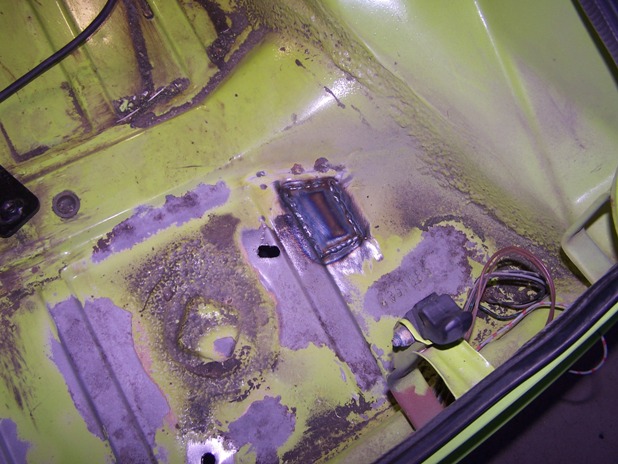 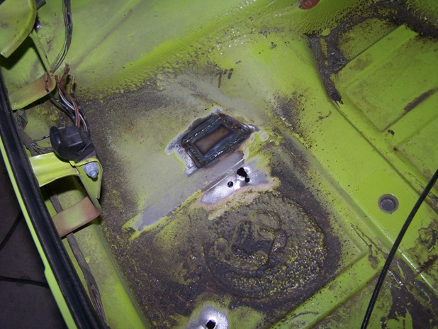
|
   |

 
|
| Spoke |
Aug 14 2007, 10:19 PM
Post
#142
|
|
Jerry Group: Members Posts: 6,978 Joined: 29-October 04 From: Allentown, PA Member No.: 3,031 Region Association: None |
Swaybar mounting brackets welded on.
Attached image(s) 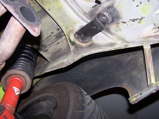 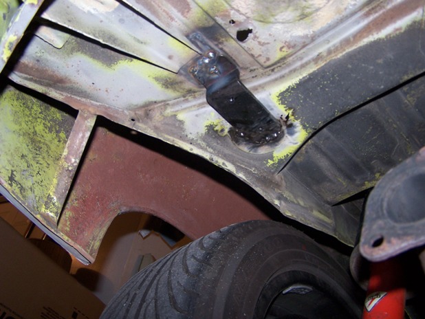
|
|
|
|
| Spoke |
Aug 19 2007, 09:33 PM
Post
#143
|
|
Jerry Group: Members Posts: 6,978 Joined: 29-October 04 From: Allentown, PA Member No.: 3,031 Region Association: None |
Finally, it's time to finish the rear flared fenders. Bondo is on and sanded. I used about a 1/2 quart of bondo, most of which has been sanded off and vacuumed up.
I'm just painting the minimum that is needed since I have less than 1 pint of paint. Got the primer on tonight and I've put the first coat of paint on. I used the full size paint gun for the primer and am using the smaller gun for the paint. Here's the fenders with primer. Attached image(s) 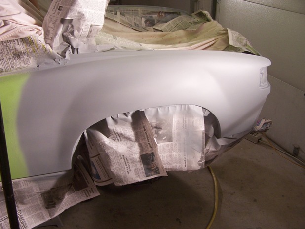 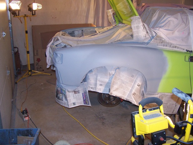
|
|
|
|
| LarryR |
Aug 19 2007, 09:58 PM
Post
#144
|
|
Senior Member Group: Members Posts: 929 Joined: 15-March 07 From: E. Bay Area, N. California Member No.: 7,604 |
(IMG:style_emoticons/default/popcorn[1].gif) (IMG:style_emoticons/default/popcorn[1].gif)
Really nice work. I am in the process of starting to go through mine. |
|
|
|
| Spoke |
Aug 19 2007, 10:47 PM
Post
#145
|
|
Jerry Group: Members Posts: 6,978 Joined: 29-October 04 From: Allentown, PA Member No.: 3,031 Region Association: None |
2 coats of paint, thinned 1:1 went on very nicely with the smaller HVLP gun. Paint looks like glass. Used very little of my paint. I should have enough to paint the rust repair on the front fender and hopefully, paint the hood.
Attached image(s) 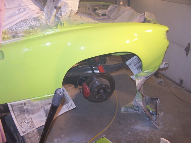 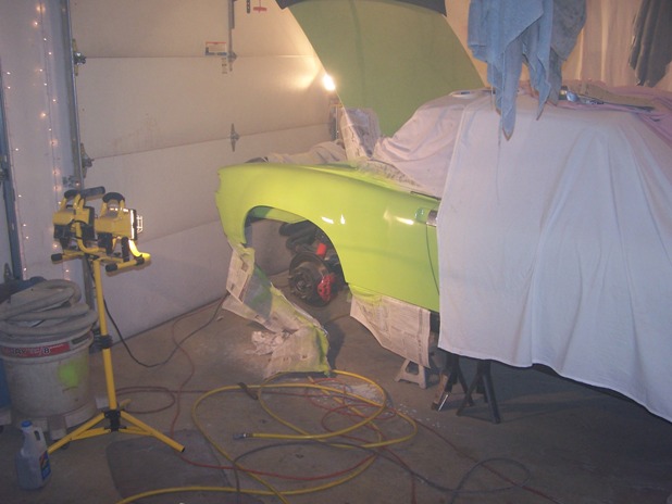
|
|
|
|
| Lou W |
Aug 20 2007, 12:40 AM
Post
#146
|
|
"Here Kitty Kitty" my ass...... Group: Members Posts: 4,109 Joined: 9-May 04 From: Roseburg, OR. Member No.: 2,039 Region Association: Spain |
Looking good, keep up the good work. (IMG:style_emoticons/default/smile.gif)
|
|
|
|
| Spoke |
Aug 31 2007, 06:35 AM
Post
#147
|
|
Jerry Group: Members Posts: 6,978 Joined: 29-October 04 From: Allentown, PA Member No.: 3,031 Region Association: None |
Time to attack the only rust through hole on the car on the passenger front fender. What gauge is the skin of a 914? It looks like it's 20ga. The cut out hole is larger than I expected but there was significant thinning of the metal around the actual rust through.
Attached image(s) 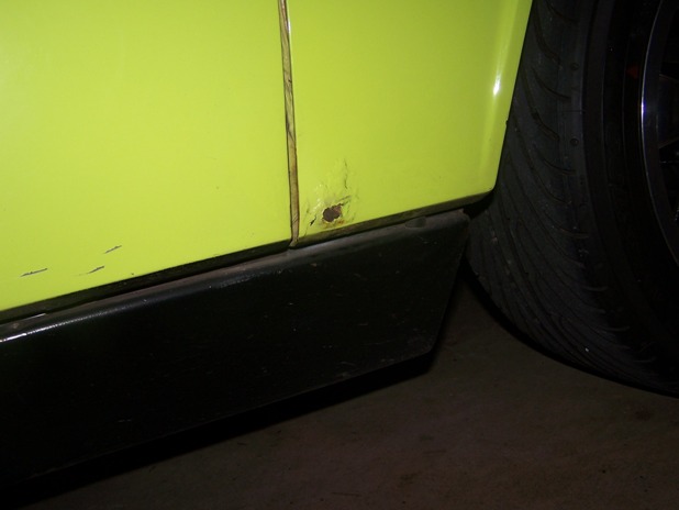 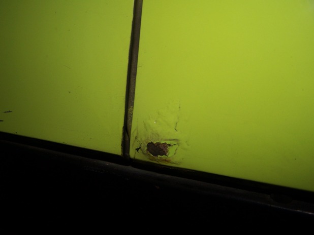 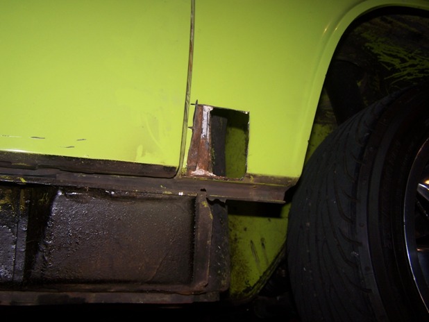
|
|
|
|
| Spoke |
Sep 2 2007, 07:41 AM
Post
#148
|
|
Jerry Group: Members Posts: 6,978 Joined: 29-October 04 From: Allentown, PA Member No.: 3,031 Region Association: None |
Pulled the passenger rocker panel off since it was showing some serious rust issues around the jack point. The rocker panel is in good shape except for this area around the jack point.
I don't know how the 914 designers could have messed this area of the car up any more. On the engine side of the long, you have the acid from the battery. On the outside of the long, you have road junk from the rear wheel accumulating on the jack point. The jack point is still sturdy as I'm able to jack the car up with no flexing. Need to get this cleaned up to see the full extent of the damage. Attached image(s) 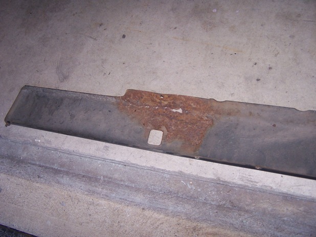 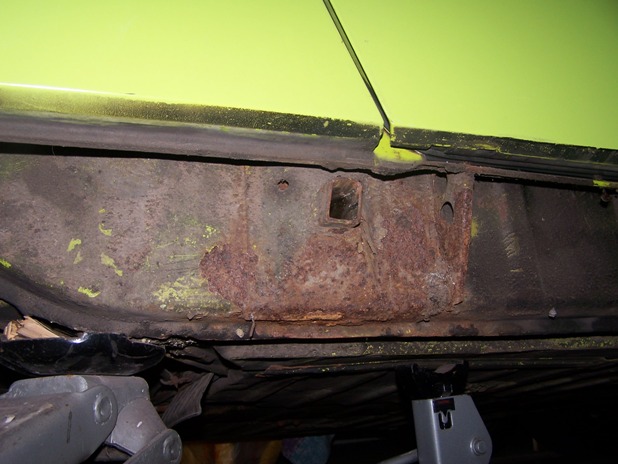 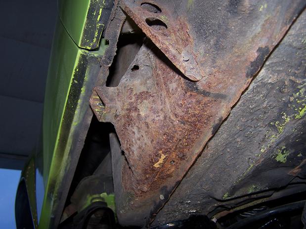
|
|
|
|
| Spoke |
Sep 2 2007, 03:48 PM
Post
#149
|
|
Jerry Group: Members Posts: 6,978 Joined: 29-October 04 From: Allentown, PA Member No.: 3,031 Region Association: None |
The rest of the passenger long looks excellent. Gotta love the 70's era rustproofing: Spray tar inside and out.
Attached image(s) 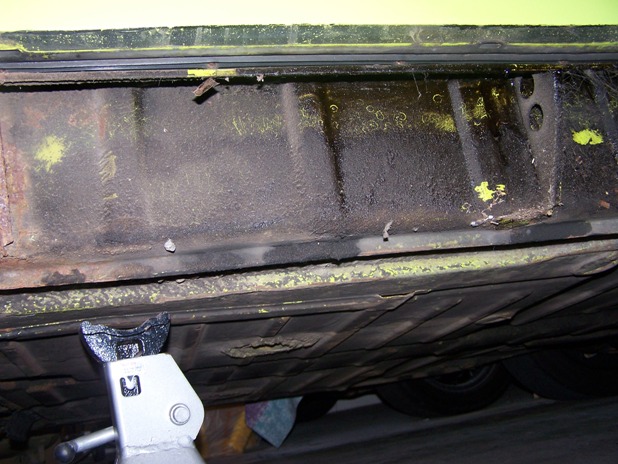 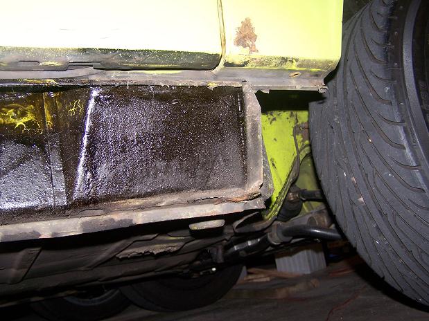
|
|
|
|
| Spoke |
Sep 3 2007, 12:32 AM
Post
#150
|
|
Jerry Group: Members Posts: 6,978 Joined: 29-October 04 From: Allentown, PA Member No.: 3,031 Region Association: None |
Ready to sandblast. Don't want sand in the car so it's wrapped up very tight with the car cover and an assortment of old bed sheets. The sheets on the driveway will help the clean-up effort as well as recycle the sand.
Note the paper jammed in a rust hole below the front fender. Found this when poking around after removing the rocker. Rust on the longitudinal is quite serious. Didn't find any holes but it doesn't look good. Attached image(s) 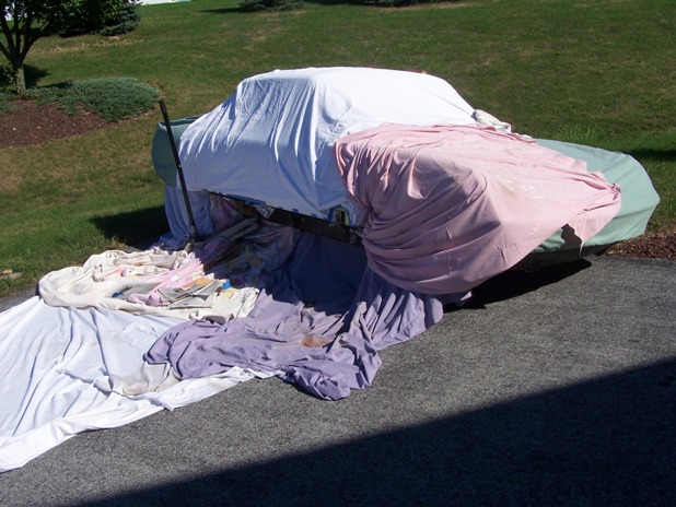 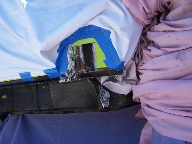 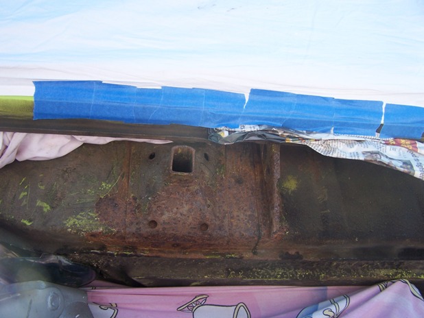 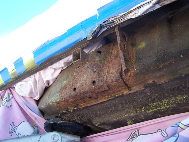
|
|
|
|
| Spoke |
Sep 3 2007, 12:40 AM
Post
#151
|
|
Jerry Group: Members Posts: 6,978 Joined: 29-October 04 From: Allentown, PA Member No.: 3,031 Region Association: None |
The long all cleaned up and primered. No rust through but there is significant damage. I'll seam weld the jack point and the one seam just in front of the jack point. The door jamb support is almost rusted off.
The front fender pic shows the rust hole in the bulkhead. Not real big but will be welded when I do the fender. Attached image(s) 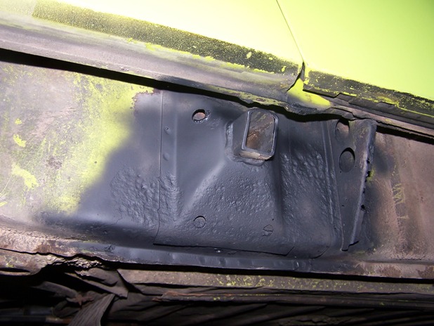 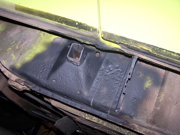 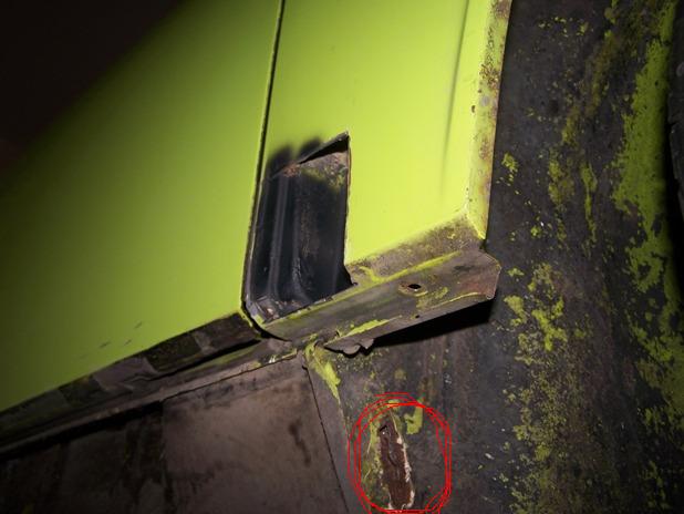
|
|
|
|
| Spoke |
Sep 3 2007, 01:00 AM
Post
#152
|
|
Jerry Group: Members Posts: 6,978 Joined: 29-October 04 From: Allentown, PA Member No.: 3,031 Region Association: None |
I could buy new rocker panels to replace the rusted ones on the car. But then again, that's why I bought a welder. First had to see how bad the damage and make a replacement piece. I made the piece before cutting out the bad stuff just so the piece would fit right.
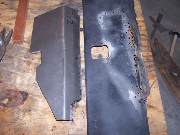 Cut out the bad stuff and test fit. Needed a little trimming here and there. 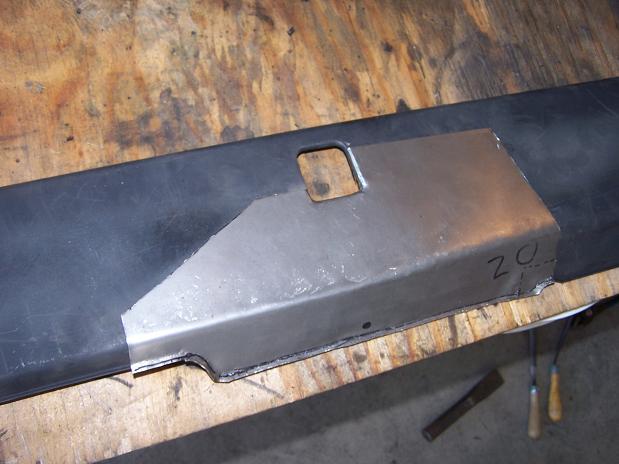 Just want to hold the piece in with some spot welds. The edges of the bottom and around the jack point were bent with a pair of pliers. Not real sophisticated but it worked. 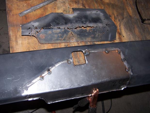 All welded in and grinded smooth. Will continue working the metal to get it flat then add some bondo to smooth the welds and paint. 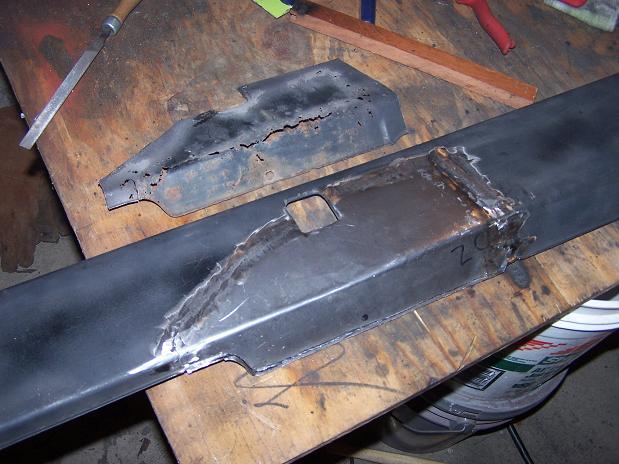 |
|
|
|
| rjames |
Sep 4 2007, 10:33 AM
Post
#153
|
|
I'm made of metal Group: Members Posts: 3,932 Joined: 24-July 05 From: Shoreline, WA Member No.: 4,467 Region Association: Pacific Northwest |
Looking good!!
|
|
|
|
| Spoke |
Sep 9 2007, 08:31 PM
Post
#154
|
|
Jerry Group: Members Posts: 6,978 Joined: 29-October 04 From: Allentown, PA Member No.: 3,031 Region Association: None |
Painted the rocker after seam welding the jack support. The brace in front of the jack support is just about gone but I don't want to dig into this area just yet. It's still ok for now.
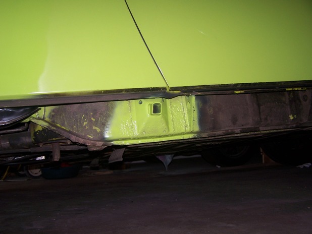 Painted the fender with my airbrush. Also painted the patch on the tub below the fender. While I was here, thought I'd paint the brake caliper. 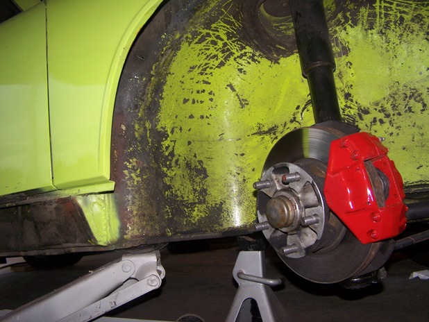 Put the rocker panel on for now so I can drive the car and have it look complete. Since I'm using screws instead of the rivets in the door jamb, I can remove and replace the rocker panel in minutes. If only the factory used screws maybe rocker panels would have been taken off on a regular basis for cleaning out all the road debris that gets deposited behind the panel and more 914's would be in better shape. 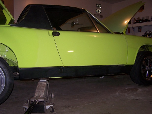 |
|
|
|
| Spoke |
Feb 3 2008, 06:42 PM
Post
#155
|
|
Jerry Group: Members Posts: 6,978 Joined: 29-October 04 From: Allentown, PA Member No.: 3,031 Region Association: None |
When I converted to 5-lug, the '87 911 front end was set up for brake wear sensors. I left the wear sensors on the pads and the mounting hardware on the struts but obviously the 914 is not set up for wear sensors.
I wanted to connect the wear sensors to the brake warning light in the dash. It should be easy to do since the parking brake-arm switch is a simple switch to ground. When the parking brake is pulled, the switch closes to ground and the brake warning light goes on. Brake pad wear sensors are simple sensors being a short circuit when the pad is ok and an open circuit when worn. Just the opposite as the parking brake switch. The wear sensors are connected in series such that when either one wears, the alarm should be activated. Since the wear sensors are opposite polarity as the parking brake switch, I needed to build an inverting circuit such that when the pads are good, the circuit should be open. When the pads are worn, the circuit should short to ground. The circuit below provides the interface between the pad sensors and the parking brake switch. For ease of implementation, I connected the output of the circuit directly across parking brake switch. The toggle switch on the circuit board is center off type so has 3 positions: UP: wear sensors connected to circuit Center: open circuit simulating worn sensors for testing. DOWN: simulates good sensors and also allows disabling of the circuit. The toggle switch is necessary in case the brake warning light is on so I can tell if the light is on for the wear sensors, the parking brake, or the master cylinder warning switch. Connector to the circuit is a PC power connector. Attached thumbnail(s) 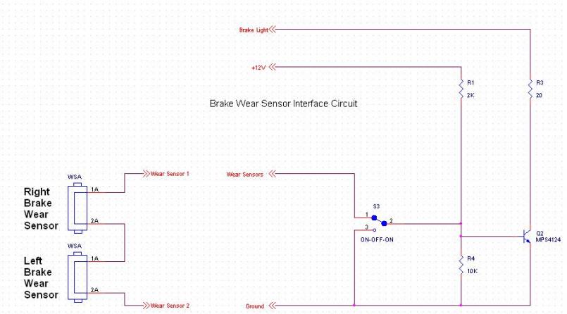 Attached image(s) 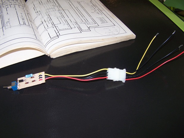 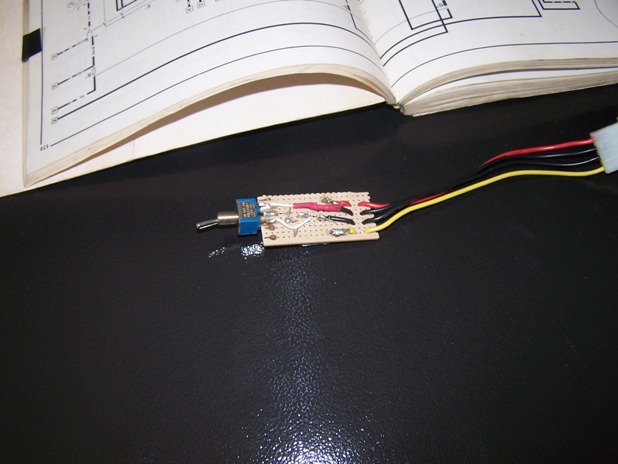
|
|
|
|
| Spoke |
Feb 3 2008, 06:55 PM
Post
#156
|
|
Jerry Group: Members Posts: 6,978 Joined: 29-October 04 From: Allentown, PA Member No.: 3,031 Region Association: None |
The chassis side connectors to the wear sensors were connected to the struts when I bought them. They were cut off so I need to make a harness with 2 wires. The harness needs to go from one connector to the other, and have wires going into the cabin to the inverter circuit.
Attached image(s) 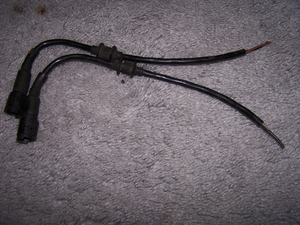
|
|
|
|
| Spoke |
Feb 3 2008, 07:26 PM
Post
#157
|
|
Jerry Group: Members Posts: 6,978 Joined: 29-October 04 From: Allentown, PA Member No.: 3,031 Region Association: None |
For my harness, I used a length of rubber hose I found in the attic. I couldn't fish 2 wires in this hose so I fished one first.
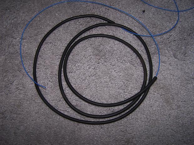 Then soldered the 2 wires to the first and pulled the 2 through. 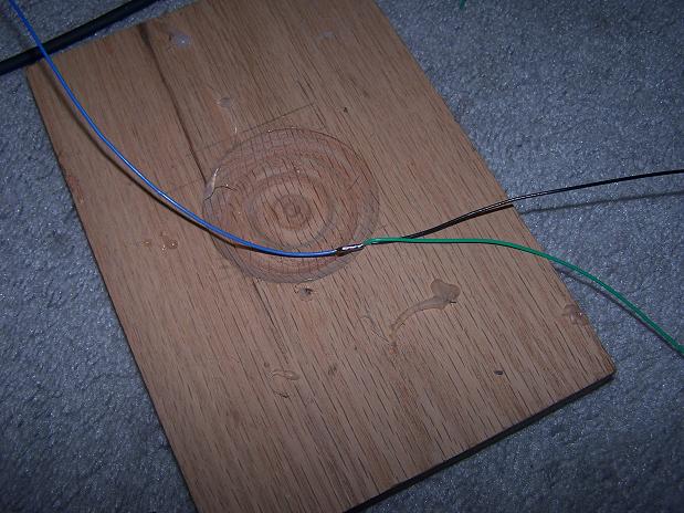 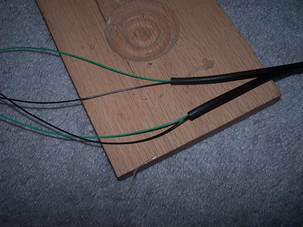 Soldered the two wires to one of the connectors. 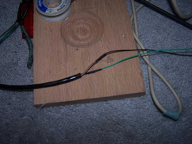 |
|
|
|
| Spoke |
Feb 3 2008, 07:33 PM
Post
#158
|
|
Jerry Group: Members Posts: 6,978 Joined: 29-October 04 From: Allentown, PA Member No.: 3,031 Region Association: None |
Once wires are soldered and heat shrink tubing applied, I pulled the hose up to the existing sheath.
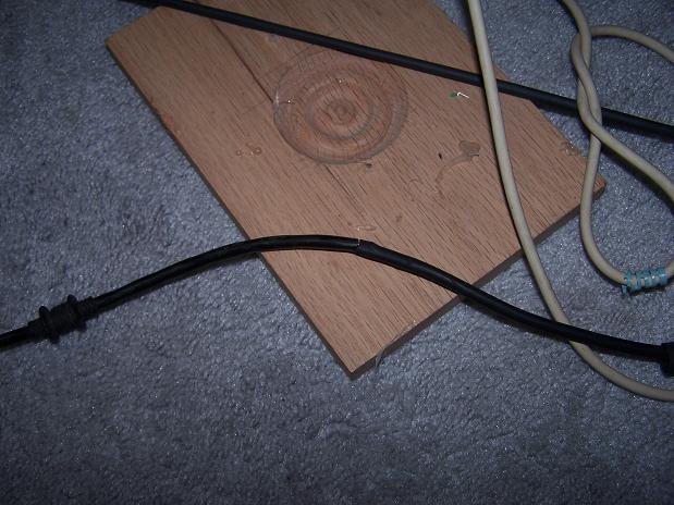 Soldered the other side and applied heat shrink tubing. I cut a small hole in the middle of the harness where the wires will go into the cabin. I left one of the wires very long so that it will be the wires into the cabin. 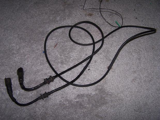 With heat shrink tubing on the cabin wire, the harness is finished and ready for install. 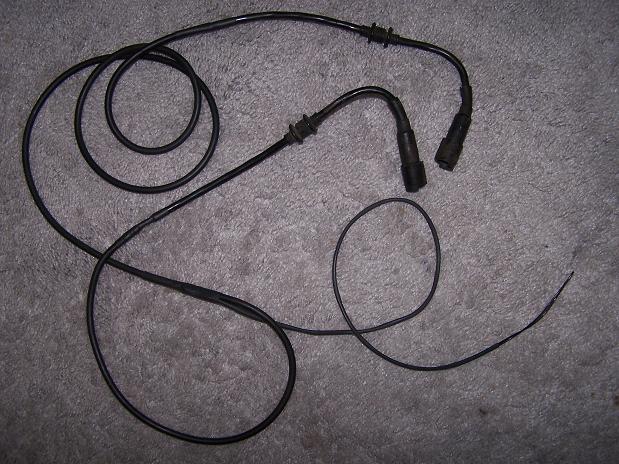 |
|
|
|
| Spoke |
Feb 3 2008, 07:49 PM
Post
#159
|
|
Jerry Group: Members Posts: 6,978 Joined: 29-October 04 From: Allentown, PA Member No.: 3,031 Region Association: None |
It's always a jackstand party when Spoke gets under the car. Can you count how many jackstands are being used?
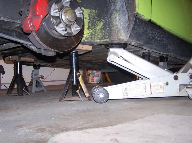 I simply tiewrapped the harness in place along the hard and flexible lines. 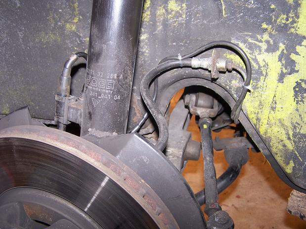 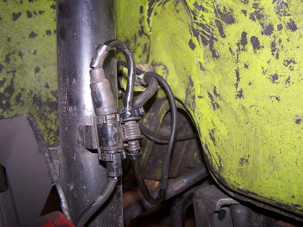 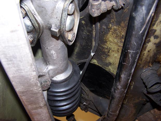 |
|
|
|
| Spoke |
Feb 3 2008, 08:12 PM
Post
#160
|
|
Jerry Group: Members Posts: 6,978 Joined: 29-October 04 From: Allentown, PA Member No.: 3,031 Region Association: None |
Pulled out the gauge to find the wire from the parking brake switch to the indicator light. The wire goes directly to the light so piece of cake to find it and splice on a wire to go to the inverter circuit.
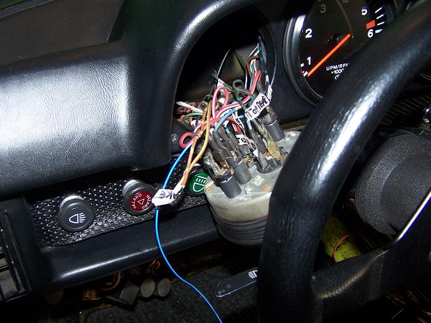 To get the wires from the undercarriage to the cabin, I drilled a small hole and installed a rubber grommet to protect the wire. Before installing the grommet, I put some paint on the exposed metal from drilling. 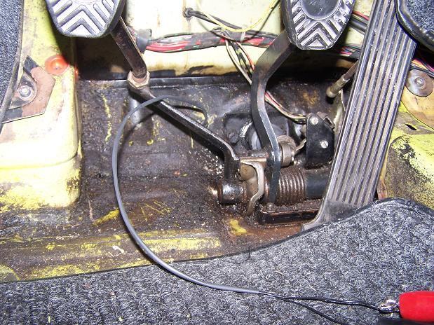 With all wiring completed, shrink wrapped and taped, the circuit will be placed on the dash support right under the radio. Circuit tested ok so it begins its life hidden under the dash. The next time I think about this circuit will be when the pads are worn. 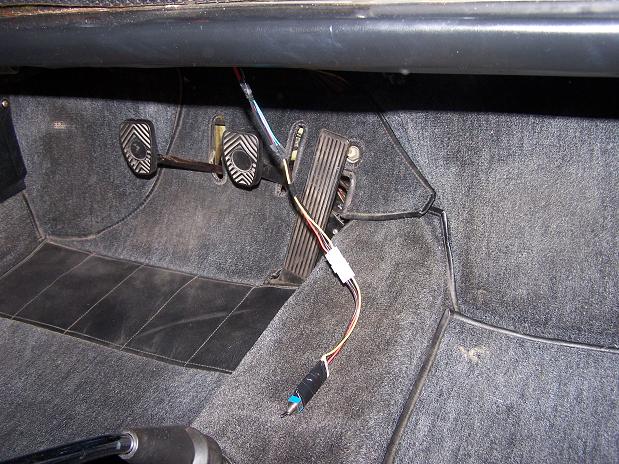 |
|
|
|
|
1 User(s) are reading this topic (1 Guests and 0 Anonymous Users)
0 Members:

|
Lo-Fi Version | Time is now: 16th May 2024 - 11:07 AM |
Invision Power Board
v9.1.4 © 2024 IPS, Inc.