|
|
|
Porsche, and the Porsche crest are registered trademarks of Dr. Ing. h.c. F. Porsche AG.
This site is not affiliated with Porsche in any way. Its only purpose is to provide an online forum for car enthusiasts. All other trademarks are property of their respective owners. |
|
|

  |

| crash914 |
 Mar 31 2006, 01:44 PM Mar 31 2006, 01:44 PM
Post
#41
|
|
its a mystery to me  Group: Members Posts: 1,826 Joined: 17-March 03 From: Marriottsville, MD Member No.: 434 Region Association: MidAtlantic Region |
I really really like the MSII set up.
Auto tune is kool and a lot easier than MS3k. I am using a V2.0 board. I might just have to go to micro squirt for kicks.....we will see.... you are close now!! let go and add one more to the list... |
   |

 
|
| DNHunt |
Apr 1 2006, 07:50 AM
Post
#42
|
|
914 Wizard? No way. I got too much to learn. Group: Members Posts: 4,099 Joined: 21-April 03 From: Gig Harbor, WA Member No.: 598 |
Herb
Autotune is cool. It's kind of a pain to change the settings for it since it is configured as it loads from an .ini file but , I suppose Eric hasn't had a chance to make it configurable in Megatune. I can hardly wait to get the extra resolution of MS II. It will clean up the surging on over run and make the idle a little more consistent. I never would have thought that the little box I put together to replace D-jet would morph into what it is now. I got it running late in 2003 and it had an 8 X8 fuel table that could run closed loop with just one AFR setting applied to the whole table. It did a passable job of imimtating D-jet. Now, I have a 12 X 12 fuel map with an 8 X 8 AFR map for closed loop. I ditched the dizzy cause I can run crankfire ignition with a 12X12 spark map on a 2270 with a pretty aggresive cam. Last weekend we ran an AX in Portland and we were loaded with all kinds of stuff so we weighed a ton. Before we left I put in a little more aggressive timing map that I had been playing with in the ECU for the trip down. The car ran hot as you might expect so we hook up the computer and put in the old map while tooling down I-5. With a little retard it cooled down and we reloaded the aggressive curve after unloading. Pretty cool. Dave |
|
|
|
| yarin |
Apr 1 2006, 08:29 PM
Post
#43
|
|
'14-X'in FOOL Group: Members Posts: 988 Joined: 13-May 03 From: Guttenberg, NJ Member No.: 693 Region Association: North East States |
some more progress today...
wired up the relay box with a little slack just in case. Finished connecting all fuel lines. Connected LC-1 with switch and LED, used common ground. Powered everything up, configured LC-1. In Logworks I set it up for 0-5V 0.5-1.5 Lambda. The sensor warmed up and gave me a reading of 20.2 in open air. I checked the output at the sensor and saw 5.0VDC. So far so good. However in Megatune I see an AFR of 25.4, its maxed out. I went to Megatune configurator, mycar, settings, lamba sensor and chose Innovative LC-1 default 0-5V 0-1.5Lamda. Then in MegaTune I selected Innovative 0.0-5.0 and uploaded the tables. However nothing changes. Any ideas? I even tried to use Generic Linear WB, still didn't work Here are a few more pics: Attached image(s) 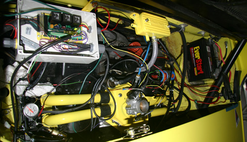
|
|
|
|
| yarin |
Apr 1 2006, 08:29 PM
Post
#44
|
|
'14-X'in FOOL Group: Members Posts: 988 Joined: 13-May 03 From: Guttenberg, NJ Member No.: 693 Region Association: North East States |
i'm damn proud of that TPS adapter. (IMG:http://www.914world.com/bbs2/html/emoticons/smilie_pokal.gif)
Attached image(s) 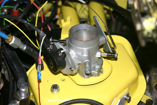
|
|
|
|
| yarin |
Apr 1 2006, 08:31 PM
Post
#45
|
|
'14-X'in FOOL Group: Members Posts: 988 Joined: 13-May 03 From: Guttenberg, NJ Member No.: 693 Region Association: North East States |
This is wherei put my LC-1.
Also notice the fuel pressure gauge on the drivers side rail. Attached image(s) 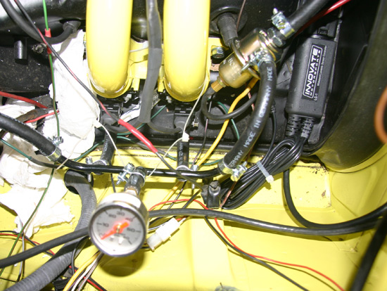
|
|
|
|
| yarin |
Apr 1 2006, 08:39 PM
Post
#46
|
|
'14-X'in FOOL Group: Members Posts: 988 Joined: 13-May 03 From: Guttenberg, NJ Member No.: 693 Region Association: North East States |
I cleaned up the gas tank compartment. The support pads for the fuel tank rubbed the paint off the car so I dremeled off a few rust spots to bare metal and sprayed it with some 3M rubber protectant. At some point in the future I want to clean everything up and POR-15 some areas, so those black rectangles are temporary.
I installed new support pads as well, sticky back from walmart for $4.00 or so. Perfect for this application. It's as if they designed it for this purpose. Can anyone tell me what front sway bar that is? |
|
|
|
| yarin |
Apr 1 2006, 08:39 PM
Post
#47
|
|
'14-X'in FOOL Group: Members Posts: 988 Joined: 13-May 03 From: Guttenberg, NJ Member No.: 693 Region Association: North East States |
oops
Attached image(s) 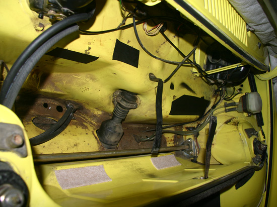
|
|
|
|
| TimT |
Apr 1 2006, 08:41 PM
Post
#48
|
|
retired Group: Members Posts: 4,033 Joined: 18-February 03 From: Wantagh, NY Member No.: 313 |
Yarin, looks like a very nice EFI conversion.. cant help you out with mega squirt though since Ive never tuned one.
swaybar? |
|
|
|
| TimT |
Apr 1 2006, 08:42 PM
Post
#49
|
|
retired Group: Members Posts: 4,033 Joined: 18-February 03 From: Wantagh, NY Member No.: 313 |
take a picture of the swaybar ends, links and hardware, makes it easier to determine brand
|
|
|
|
| yarin |
Apr 1 2006, 08:42 PM
Post
#50
|
|
'14-X'in FOOL Group: Members Posts: 988 Joined: 13-May 03 From: Guttenberg, NJ Member No.: 693 Region Association: North East States |
and another of the WBO2 sensor and wire routing.
Attached image(s) 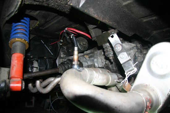
|
|
|
|
| yarin |
Apr 1 2006, 08:44 PM
Post
#51
|
||
|
'14-X'in FOOL Group: Members Posts: 988 Joined: 13-May 03 From: Guttenberg, NJ Member No.: 693 Region Association: North East States |
here ya go (IMG:http://www.914world.com/bbs2/html/emoticons/smile.gif) Attached image(s) 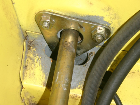
|
||
|
|
|
||
| TimT |
Apr 1 2006, 08:45 PM
Post
#52
|
|
retired Group: Members Posts: 4,033 Joined: 18-February 03 From: Wantagh, NY Member No.: 313 |
hmmmmm the end links etc that connect to the a-arm..
looks suspiciously like a weltmiester so far |
|
|
|
| Jeff Nelson |
Apr 1 2006, 08:58 PM
Post
#53
|
|
Newbie Group: Members Posts: 31 Joined: 27-July 05 From: Santa Rosa, CA Member No.: 4,487 |
yarin, Yes, nice TPS adapter! I just started making mine today so I can definitely relate. What TPS are you using? I hope it's cheaper than the Bosch part that I'm adapting.
I'm trying to figure out what everything is in your close up of the plenum. You've got a cover plate where the cold start injector would mount, a bolt where the air temperature sensor goes and what is the sensor attached with a bit of hose from a vacuum port? What air temp sensor are you using? Your choice of yellow looks great and makes it really easy to see details in the pictures that you've posted. Nice work! |
|
|
|
| yarin |
Apr 1 2006, 09:08 PM
Post
#54
|
||
|
'14-X'in FOOL Group: Members Posts: 988 Joined: 13-May 03 From: Guttenberg, NJ Member No.: 693 Region Association: North East States |
Thanks Jeff! Good observations... TPS - junkyard $10 off a mazda. Standard D-shaft. Here are my plenum features: Cold start injector blockoff Air temp block off. I'm using the standard GM temp sensor in my custom PVC intake. The vacuum port is just a complex bunch of adapters i found laying around the garage. It tees off to the MS map sensor and manifold referenced adjustable fuel pressure regulator. stock Fast idle valve Once its finished i'll clean it up a bit and start a site with all of the details. I hope to try to fire it up by Wednesday (IMG:http://www.914world.com/bbs2/html/emoticons/smile.gif) |
||
|
|
|
||
| DNHunt |
Apr 2 2006, 07:14 AM
Post
#55
|
|
914 Wizard? No way. I got too much to learn. Group: Members Posts: 4,099 Joined: 21-April 03 From: Gig Harbor, WA Member No.: 598 |
Yarin
Get a raw voltage off of the LC-1 and then compare it to the generated table that MS uses. Then trace that circuit at least to the DB37 coming out of the relay box. I can't remember for sure but, I'm not sure MS is getting the signal. Also, my O2 sensor will not warmup and report correctly until on just battery voltage. The alternator has to be functioning. I'm not sure why that is except I suspect it draws a lot of current to heat the sensor. It is also possible that MS doesn't reference the voltage right until the alternator is up. If you take a look at the reported voltage to the MS ECU in Megatune it is probably under reported. Without the engine running it usually will report around 11.5 V at the ECU and I have 12.6 or so at the battery. Dave |
|
|
|
| Tom Perso |
Apr 2 2006, 08:23 AM
Post
#56
|
|
Crazy from the Cold... Group: Members Posts: 647 Joined: 8-August 03 From: Kalamazoo, MI Member No.: 1,003 |
Could you throw a big battery charger/starter on to "pump" up the voltage a bit to see if that helps with the heating element?
I know MS will run on 9 volts, but all the ancillary stuff may take more. Looks great so far. I like the box for the relay setup. Tom |
|
|
|
| yarin |
Apr 2 2006, 08:31 AM
Post
#57
|
|
'14-X'in FOOL Group: Members Posts: 988 Joined: 13-May 03 From: Guttenberg, NJ Member No.: 693 Region Association: North East States |
I think the sensor is heating up, if it couldn't due to a lack of supplied current it would throw an error. I tried to power up the sensor off an AC/DC wall adapter and it gave a heater error. However now that its installed in the car it appears to be functioning properly. The problem is on the MS side, i'll trace it back through the relay box and check the tables.
If I hookup TPS Vref to the O2 input shouldn't that be a good test of the system in an attempt to display an AFR of 20 (5V input)?? |
|
|
|
| yarin |
Apr 2 2006, 09:50 AM
Post
#58
|
|
'14-X'in FOOL Group: Members Posts: 988 Joined: 13-May 03 From: Guttenberg, NJ Member No.: 693 Region Association: North East States |
The only time the AFR changes is when the lc-1 is warming up, then the AFR drops to the bottom of the range. But as soon as it warms up it shoots to 25.5AFR.
I hooked the stim up to the MS again. I checked the potentiometer output and saw 0-1V on the O2 simulator. So I setup a custom wideband output in MS under Calibrate AFR for 0-1V 10-20AFR. That worked perfectly. Then i decided to change my LC-1 to output 0-1V and 10-20AFR. With MS expecting 0-5V I saw ~14.5AFR with a known output of 1V from the sensor. So something is off in the tables. Then I set MS to 0-1V in Calibrate AFR in MS. What do u know.... BAM 20.5AFR! Excellent. For some reason it doesn't like the 5V signal, or the tables aren't correct. How do I check the tables? Where can i find the text table? |
|
|
|
| DNHunt |
Apr 3 2006, 08:17 AM
Post
#59
|
|
914 Wizard? No way. I got too much to learn. Group: Members Posts: 4,099 Joined: 21-April 03 From: Gig Harbor, WA Member No.: 598 |
Yarin
I'm not sure where to find that info. Maybe the Table editor. So, did I read it right? Do you have it straightened ou? Dave |
|
|
|
| crash914 |
Apr 3 2006, 08:47 AM
Post
#60
|
|
its a mystery to me Group: Members Posts: 1,826 Joined: 17-March 03 From: Marriottsville, MD Member No.: 434 Region Association: MidAtlantic Region |
You might have to modify the .ini file...I think that you have to specify 0 to 5 volts in a couple of places... I remember a couple of wide band questions....
|
|
|
|
|
1 User(s) are reading this topic (1 Guests and 0 Anonymous Users)
0 Members:

|
Lo-Fi Version | Time is now: 1st May 2024 - 09:28 PM |
Invision Power Board
v9.1.4 © 2024 IPS, Inc.