|
|
|
Porsche, and the Porsche crest are registered trademarks of Dr. Ing. h.c. F. Porsche AG.
This site is not affiliated with Porsche in any way. Its only purpose is to provide an online forum for car enthusiasts. All other trademarks are property of their respective owners. |
|
|


| ottox914 |
 Jun 12 2006, 06:58 AM Jun 12 2006, 06:58 AM
Post
#41
|
|
The glory that once was.  Group: Members Posts: 1,302 Joined: 15-December 03 From: Mahtomedi, MN Member No.: 1,438 Region Association: Upper MidWest |
I've taken the plunge, sent $$$ to Mark, and ordered SDS for my 914. I expect with mail delays to the great white north, for delivery to be 3-4 weeks out, but thats O.K. I'll be updating this thread with photos and comentary about the install. Here's the starters-
Motor is a mostly stock 2.0, euro pistons and cyls, and a little head shaving to up the c/r. Motor was built by Brad Mayeur about 50K ago. Stock cam, valves. Now for the good stuff. I purchased from Jake some TWM ITB's, manifolds, air cleaners. The car was running a Kerry Hunter exhaust and super trapp exhaust. The SDS system will be a fuel and ignition/coil pac system, so I'll be dropping the motor to more easily axcess the front for the hall sensor install. Along the way I'll be replacing the engine shelf to engine tin rubber seals, and ordering/installing some of Chris Foley's replacement fuel lines. Last night I prepped the motor for the drop, and found some additional things to fix. Theres a big suprize. NOT. While the firewall and shift rod guide bushings were fine, no more than 1/16 play between the rod and bushing, the ball cup bushing was, well, GONE! There was the bottom half of the bushing still in the cup, but where the ball on the shift linkage would contact the nylon, it was worn/broken off into pieces. No wonder it ground a little... and there was a torn motor mount, and I had a couple head studs stick in their EZ outs, and the whole mess backed out of the head, rather than the nut coming off the stud, or the stud coming out of the EZ out... I won't bore you with photos of the drop, we've all done that a hundred times, but here are some photos of the mock up of the ITB's and a spair coil pac floating around the shop, done to get more accurate measurements for the harness to be constructed/supplied by SDS. The wires for the injectors and sensors will run across the back trunk firewall, under all the new fuel lines, and attach to the back firewall with some neat "tree" style zip ties I found, where the plastic "tree" will go into 2 holes in the back trunk firewall, and tuck the wires up and out of the way. For the crank sensor, I've got a pully coming from a 914 A/C car to test fit. I may use that, or I may have a machinist friend make an aluminum disc to mount the trigger mags to. I'll have to get it appart and see what it all looks like, and what will work best. Now, some photos- Attached thumbnail(s) 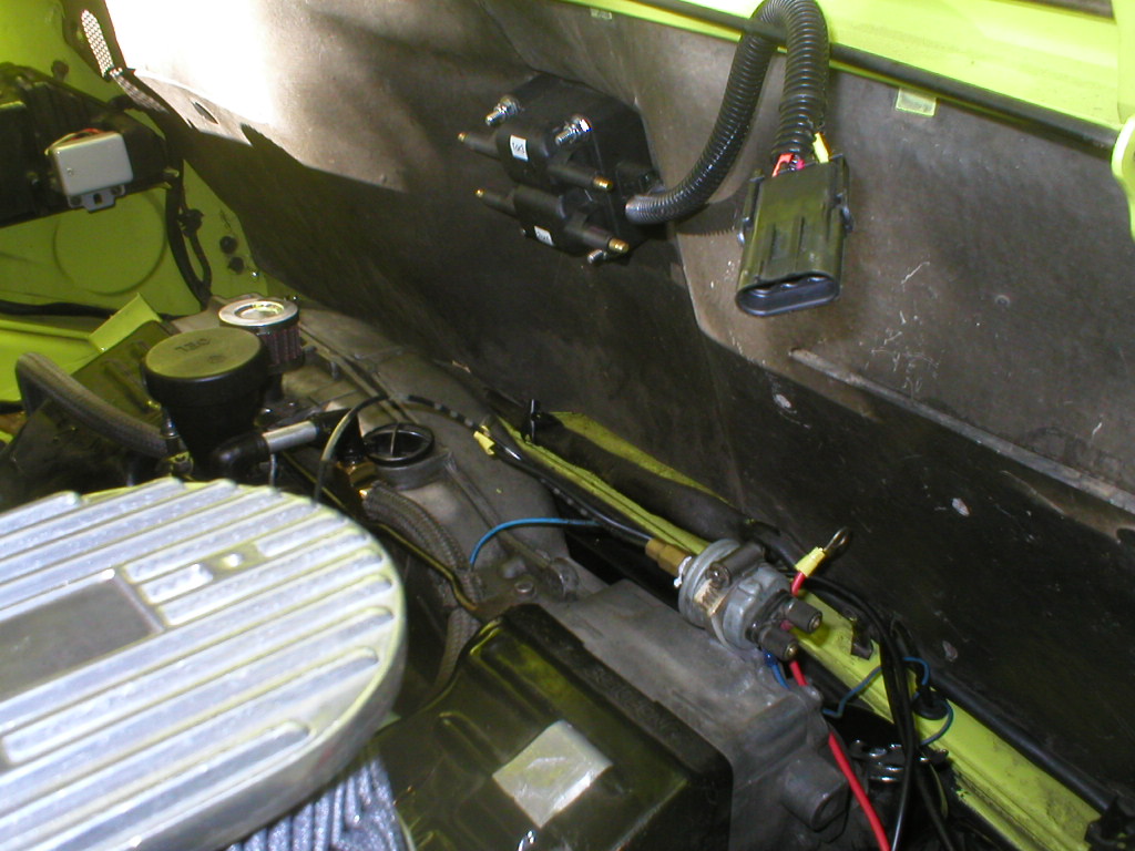
|
   |

 
|
Posts in this topic
 ottox914 My SDS install Jun 12 2006, 06:58 AM
 ottox914 ITB left Jun 12 2006, 06:59 AM ottox914 ITB right Jun 12 2006, 07:00 AM Mark Henry I forget how long my injector harness is, but the ... Jun 12 2006, 07:23 AM Mark Henry BTW your aircleaner is crushing because you're... Jun 12 2006, 07:26 AM ottox914 Good guess on the aircleaner, but in reality, it w... Jun 12 2006, 07:33 AM Gint
   |
1 User(s) are reading this topic (1 Guests and 0 Anonymous Users)
0 Members:

|
Lo-Fi Version | Time is now: 21st June 2026 - 04:41 AM |
Invision Power Board
v9.1.4 © 2026 IPS, Inc.
| All rights reserved 914World.com © since 2002 |
|
914World.com is the fastest growing online 914 community! We have it all, classifieds, events, forums, vendors, parts, autocross, racing, technical articles, events calendar, newsletter, restoration, gallery, archives, history and more for your Porsche 914 ... |