|
|
|
Porsche, and the Porsche crest are registered trademarks of Dr. Ing. h.c. F. Porsche AG.
This site is not affiliated with Porsche in any way. Its only purpose is to provide an online forum for car enthusiasts. All other trademarks are property of their respective owners. |
|
|

  |

| 914forme |
 Apr 23 2006, 06:48 PM Apr 23 2006, 06:48 PM
Post
#1
|
|
Times a wastin', get wrenchin'!  Group: Members Posts: 3,899 Joined: 24-July 04 From: Dayton, Ohio Member No.: 2,388 Region Association: None |
Well here it goes the step by step instructions on how to build one of the kits. Since I helped do the original production run, back in the day, its been about 11 years ago since we did these. But there is interest in it so I will show you how.
Step one, the original kit. It included a gauge face, a backing plate and a ground lug. Also included instructions on how to do this, and some of the items where real PITAs to do. I will included some changes I do, and items that might make the installation a little easier. Attached image(s) 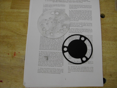
|
   |

 
|
| 914forme |
Apr 23 2006, 06:51 PM
Post
#2
|
|
Times a wastin', get wrenchin'! Group: Members Posts: 3,899 Joined: 24-July 04 From: Dayton, Ohio Member No.: 2,388 Region Association: None |
Next you have to gather two instruments, chance are one you already have. It is what everybody calls a 914 combo gauge. Most have a huge brake warning light, rarer are the ones that include an oil temperature gauge. So you can take one out of your car, or source a different one.
Attached image(s) 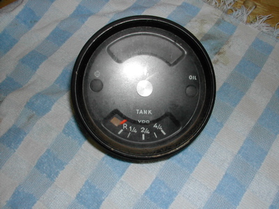
|
|
|
|
| 914forme |
Apr 23 2006, 07:00 PM
Post
#3
|
|
Times a wastin', get wrenchin'! Group: Members Posts: 3,899 Joined: 24-July 04 From: Dayton, Ohio Member No.: 2,388 Region Association: None |
The back of the gauge will look like this notice the spade connectors. This is the early style - I will show you how to setup for the latter style gauge also. It is much easier to mount.
Attached image(s) 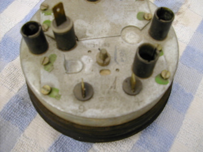
|
|
|
|
| 914forme |
Apr 23 2006, 07:01 PM
Post
#4
|
|
Times a wastin', get wrenchin'! Group: Members Posts: 3,899 Joined: 24-July 04 From: Dayton, Ohio Member No.: 2,388 Region Association: None |
A late model gauge will have a connector like this.
Attached image(s) 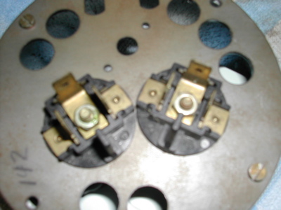
|
|
|
|
| 914forme |
Apr 23 2006, 07:02 PM
Post
#5
|
|
Times a wastin', get wrenchin'! Group: Members Posts: 3,899 Joined: 24-July 04 From: Dayton, Ohio Member No.: 2,388 Region Association: None |
The other is a 911 oil temperature gauge and pressure gauge, you need the latter style, it looks something like this. Not this is an early model with spade connectors. I have one already apart, that has the correct late style connectors. Jot down the year of the car that the gauge came out of it you know it. You will need it latter to pick the correct senders. Chart will fill in the details.
This is an early gauge - its the only one I had together. Attached image(s) 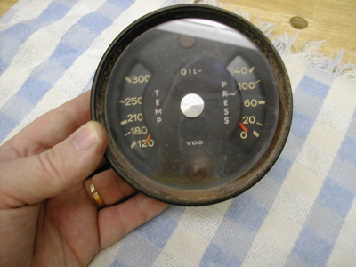
|
|
|
|
| 914forme |
Apr 23 2006, 07:04 PM
Post
#6
|
|
Times a wastin', get wrenchin'! Group: Members Posts: 3,899 Joined: 24-July 04 From: Dayton, Ohio Member No.: 2,388 Region Association: None |
The connectors are the same as posted two above. You really need these, you could modify the backer to hold the early style gauges, but you ill be hating life, they are a real PITA.
|
|
|
|
| 914forme |
Apr 23 2006, 07:07 PM
Post
#7
|
|
Times a wastin', get wrenchin'! Group: Members Posts: 3,899 Joined: 24-July 04 From: Dayton, Ohio Member No.: 2,388 Region Association: None |
Tools of the trade:
Screw drivers flate blade 7mm nut driver Pliers Nibblers Snips A large Drill bit, I use a 3/4 inch, but a 1/2 will do. A soldering Iron if you are using the early style fuel gauge. Plenty of time and patience Attached image(s) 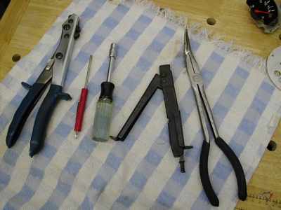
|
|
|
|
| 914forme |
Apr 23 2006, 07:10 PM
Post
#8
|
|
Times a wastin', get wrenchin'! Group: Members Posts: 3,899 Joined: 24-July 04 From: Dayton, Ohio Member No.: 2,388 Region Association: None |
First step is to remove all the gauge mechanisms out of the back side of the gauges bodies.
4 screws hold these in place. Place the gauge face down on a cloth and take them out. Keep all your parts until you finish the build. Attached image(s) 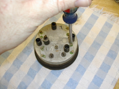
|
|
|
|
| 914forme |
Apr 23 2006, 07:15 PM
Post
#9
|
|
Times a wastin', get wrenchin'! Group: Members Posts: 3,899 Joined: 24-July 04 From: Dayton, Ohio Member No.: 2,388 Region Association: None |
The fuel gauge will come out, but you can't pull it straight up. You must tip it and raise the right side up first if your looking at it closest to you. Just be gentle it does come out of there. (IMG:style_emoticons/default/smash.gif)
Attached image(s) 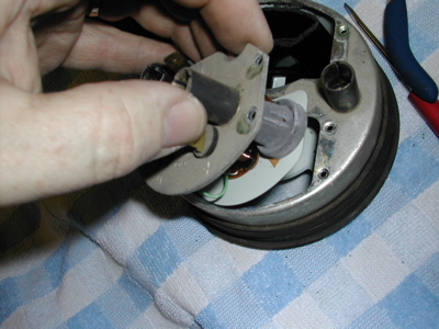
|
|
|
|
| 914forme |
Apr 23 2006, 07:17 PM
Post
#10
|
|
Times a wastin', get wrenchin'! Group: Members Posts: 3,899 Joined: 24-July 04 From: Dayton, Ohio Member No.: 2,388 Region Association: None |
Here it is out of the gauge front view, and rear view also.
Attached image(s) 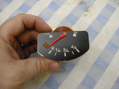 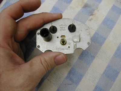
|
|
|
|
| 914forme |
Apr 23 2006, 07:21 PM
Post
#11
|
|
Times a wastin', get wrenchin'! Group: Members Posts: 3,899 Joined: 24-July 04 From: Dayton, Ohio Member No.: 2,388 Region Association: None |
I like to take them apart along the way. It is just how I do it, not sure why its just how I have done them for years. So first you need to heat up the soldering iron, and remove the solder from the two spade connectors. I heat the solder up, and strike the gauge back against the bench with a tap, the solder will fall off. Watch out you can burn yourself good doing this. You could also use solder wick if you wanted.
Attached image(s) 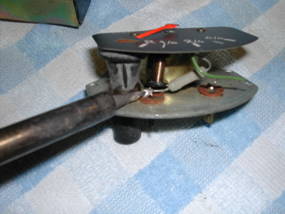
|
|
|
|
| 914forme |
Apr 23 2006, 07:24 PM
Post
#12
|
|
Times a wastin', get wrenchin'! Group: Members Posts: 3,899 Joined: 24-July 04 From: Dayton, Ohio Member No.: 2,388 Region Association: None |
Next you remove the gauge mechanism from the mounting plate, on the early 914 fuel gauge it is one simple nut. It requires a special tool, if you want to keep it concourse, I use this! A pair of BMFP
Attached image(s) 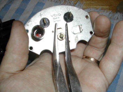
|
|
|
|
| 914forme |
Apr 23 2006, 07:30 PM
Post
#13
|
|
Times a wastin', get wrenchin'! Group: Members Posts: 3,899 Joined: 24-July 04 From: Dayton, Ohio Member No.: 2,388 Region Association: None |
Next is wheere the fun really begins, removing the spade connectors from the mounting plate.
First you must bend up the little tabes that hold the connector onto the mounting plate. There are two pe connector, be really careful or else you break the conector. And life becomes a little but harder. So first I take a really small screwdriver and wedge it between the fiber insulator and the gauge mount plate lik this. Slide it in and gentaly pry up. Next I do the same ontop of the fiber insulator, and last I grab it with a small set of kneedle knows pliers and make it straight. Attached image(s) 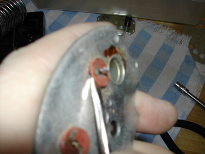 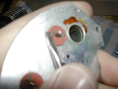
|
|
|
|
| 914forme |
Apr 23 2006, 07:33 PM
Post
#14
|
|
Times a wastin', get wrenchin'! Group: Members Posts: 3,899 Joined: 24-July 04 From: Dayton, Ohio Member No.: 2,388 Region Association: None |
Note to self pull camera back, dang those where blurry.
Okay I take my small pliers and screw drivers and gently pull the fiber ring up off the connectors. the connector will fall out after this is done, so make sure you track where it goes. Attached image(s) 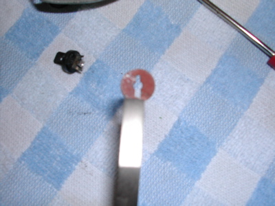
|
|
|
|
| 914forme |
Apr 23 2006, 07:36 PM
Post
#15
|
|
Times a wastin', get wrenchin'! Group: Members Posts: 3,899 Joined: 24-July 04 From: Dayton, Ohio Member No.: 2,388 Region Association: None |
Left is a good connector, right is one I screwed up. (IMG:style_emoticons/default/headbang.gif) so be careful, take your time, or else you will be looking at other ways of fixing this problem.
Attached image(s) 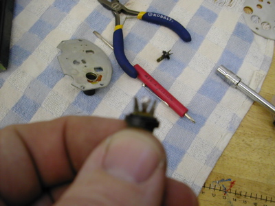 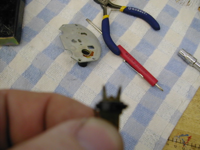
|
|
|
|
| 914forme |
Apr 23 2006, 07:39 PM
Post
#16
|
|
Times a wastin', get wrenchin'! Group: Members Posts: 3,899 Joined: 24-July 04 From: Dayton, Ohio Member No.: 2,388 Region Association: None |
Next up the 911 oil temp and pressure gauge mechanism disassembly, the are both the same so just repeat and rinse these twice. Well three times if you use a late style fuel gauge. You will now see why I recommend using the late style fuel gauge. This is so much easier, and you don't risk getting burnt. Tip here: stuff a little paper into the tip of your 7-mm socket or nut driver, it will make it easier to reassemble the gauge pieces latter. The nut won't burry itself in your socket and never start back on the shaft. Trust me there is no room for your fingers in there. Second is who the nut will look since you modded your nut driver.
Attached image(s) 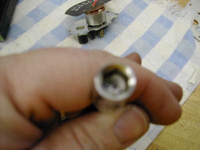 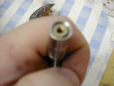
|
|
|
|
| 914forme |
Apr 23 2006, 07:47 PM
Post
#17
|
|
Times a wastin', get wrenchin'! Group: Members Posts: 3,899 Joined: 24-July 04 From: Dayton, Ohio Member No.: 2,388 Region Association: None |
Pretty simple here you take your 7-mm nut driver. And back out the nut in the center of the three spade connectors. The center ground lug will come off with the nut. If you can not remove the connector from the mount, you can take that small screw driver and pry up gently it will pop off, and everything will fall apart.
Attached image(s) 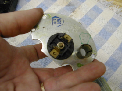 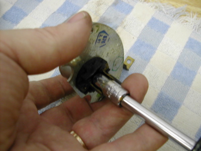 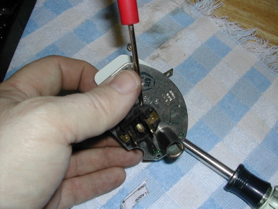
|
|
|
|
| 914forme |
Apr 23 2006, 07:50 PM
Post
#18
|
|
Times a wastin', get wrenchin'! Group: Members Posts: 3,899 Joined: 24-July 04 From: Dayton, Ohio Member No.: 2,388 Region Association: None |
Now the best part, put all these dissasembled pieces into a storage container re-assembled. Note the order of how the early fuel gauge goes togtheer.
Attached image(s) 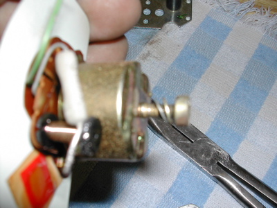 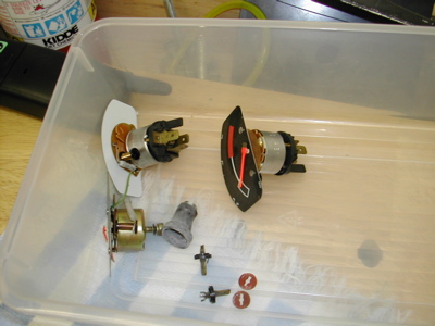
|
|
|
|
| 914forme |
Apr 23 2006, 07:58 PM
Post
#19
|
|
Times a wastin', get wrenchin'! Group: Members Posts: 3,899 Joined: 24-July 04 From: Dayton, Ohio Member No.: 2,388 Region Association: None |
Now onto the real fun, takeing the bevel apart. The pros just cut them off you are about to see why. First remove the rubber surround. Next you need to have a gental touch and don't worry about the paint that flakes off, thats fixable. You strat by gentally twisiting your screw driver, I made a special tool for this I have since lost. (IMG:style_emoticons/default/confused24.gif)
Move the bevel metal out a little at a time. A trick I use is I only go around the bevel , 2/3rs of the way. With some minor struggle it will come off. And then you have less to repair latter. Take your time here. It is worth it in the long run, trust me. (IMG:style_emoticons/default/biggrin.gif) Attached image(s) 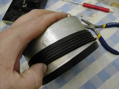 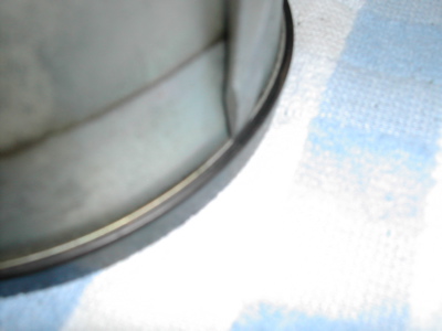 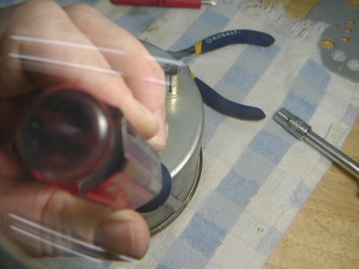 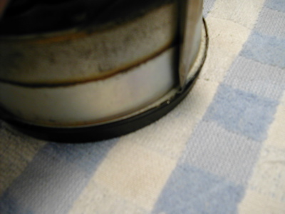 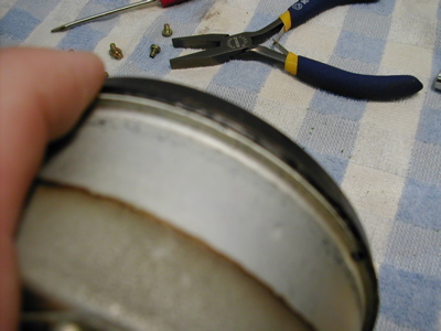 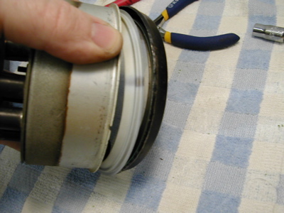
|
|
|
|
| 914forme |
Apr 23 2006, 08:01 PM
Post
#20
|
|
Times a wastin', get wrenchin'! Group: Members Posts: 3,899 Joined: 24-July 04 From: Dayton, Ohio Member No.: 2,388 Region Association: None |
Boy I wish I had photshop right now. The screw driver is pointing to where I started and stopped my bevel decrimping. About 2/3rds of the way around.
Attached image(s) 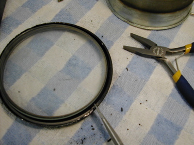 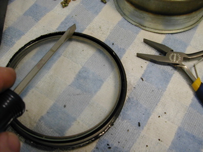
|
|
|
|
|
1 User(s) are reading this topic (1 Guests and 0 Anonymous Users)
0 Members:

|
Lo-Fi Version | Time is now: 8th June 2026 - 10:31 PM |
Invision Power Board
v9.1.4 © 2026 IPS, Inc.