|
|
|
Porsche, and the Porsche crest are registered trademarks of Dr. Ing. h.c. F. Porsche AG.
This site is not affiliated with Porsche in any way. Its only purpose is to provide an online forum for car enthusiasts. All other trademarks are property of their respective owners. |
|
|


| 914forme |
 Apr 23 2006, 06:48 PM Apr 23 2006, 06:48 PM
Post
#41
|
|
Times a wastin', get wrenchin'!  Group: Members Posts: 3,899 Joined: 24-July 04 From: Dayton, Ohio Member No.: 2,388 Region Association: None |
Well here it goes the step by step instructions on how to build one of the kits. Since I helped do the original production run, back in the day, its been about 11 years ago since we did these. But there is interest in it so I will show you how.
Step one, the original kit. It included a gauge face, a backing plate and a ground lug. Also included instructions on how to do this, and some of the items where real PITAs to do. I will included some changes I do, and items that might make the installation a little easier. Attached image(s) 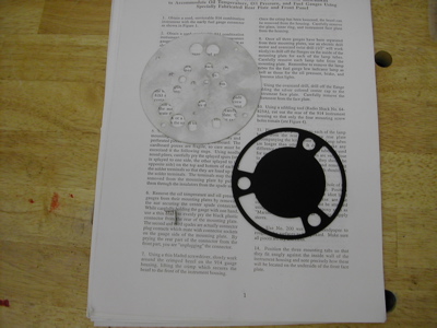
|
   |

 
|
Posts in this topic
 914forme Build your own Combo (904) Gauge Apr 23 2006, 06:48 PM
 914forme Next you have to gather two instruments, chance ar... Apr 23 2006, 06:51 PM 914forme The back of the gauge will look like this notice t... Apr 23 2006, 07:00 PM 914forme A late model gauge will have a connector like this... Apr 23 2006, 07:01 PM 914forme The other is a 911 oil temperature gauge and press... Apr 23 2006, 07:02 PM 914forme The connectors are the same as posted two above. ... Apr 23 2006, 07:04 PM 914forme Tools of the trade:
Screw drivers flate blade
7mm... Apr 23 2006, 07:07 PM 914forme First step is to remove all the gauge mechanisms o... Apr 23 2006, 07:10 PM 914forme The fuel gauge will come out, but you can't pu... Apr 23 2006, 07:15 PM 914forme Here it is out of the gauge front view, and rear v... Apr 23 2006, 07:17 PM 914forme I like to take them apart along the way. It is ju... Apr 23 2006, 07:21 PM 914forme Next you remove the gauge mechanism from the mount... Apr 23 2006, 07:24 PM 914forme Next is wheere the fun really begins, removing the... Apr 23 2006, 07:30 PM 914forme Note to self pull camera back, dang those where bl... Apr 23 2006, 07:33 PM 914forme Left is a good connector, right is one I screwed u... Apr 23 2006, 07:36 PM 914forme Next up the 911 oil temp and pressure gauge mechan... Apr 23 2006, 07:39 PM 914forme Pretty simple here you take your 7-mm nut driver. ... Apr 23 2006, 07:47 PM 914forme Now the best part, put all these dissasembled piec... Apr 23 2006, 07:50 PM 914forme Now onto the real fun, takeing the bevel apart. T... Apr 23 2006, 07:58 PM 914forme Boy I wish I had photshop right now. The screw dr... Apr 23 2006, 08:01 PM 914forme This is the order that the bevel comes apart.
1. ... Apr 23 2006, 08:05 PM 914forme Next up after the glass is removed, you have an in... Apr 23 2006, 08:07 PM 914forme After that we have the inner guts of the gauge. S... Apr 23 2006, 08:09 PM 914forme They are easily removed with a gentle pull. Apr 23 2006, 08:10 PM 914forme Next up we must remove all the light bulb tube hol... Apr 23 2006, 08:15 PM 914forme Now you just pull them out. You must now repeat t... Apr 23 2006, 08:19 PM 914forme This is a good place for me to stop for the night. Apr 23 2006, 08:20 PM 914forme Here is what happens when your bit grabs one of th... May 7 2006, 05:36 PM 914forme Now onto the cutting of the rear gauge face. Ther... May 7 2006, 05:42 PM 914forme I like to test fit the gauge kit back onto the org... May 7 2006, 05:46 PM 914forme Next you draw out your cut lines. I happen to lea... May 7 2006, 05:48 PM 914forme Now it is simple you just cut away everything that... May 7 2006, 05:52 PM 914forme Now I used to use a hand nibbler like this, it was... May 7 2006, 05:56 PM 914forme So when your done it should look like this. May 7 2006, 05:57 PM 914forme I once again test fit the back, just to make sure ... May 7 2006, 06:01 PM 914forme Next if you are lucky enough to find a late style ... May 7 2006, 06:40 PM 914forme Now you need to test fit the light tubes. May 7 2006, 06:41 PM 914forme Mix up the epoxy, mine sets in 24 - 48 hours. You... May 7 2006, 06:45 PM 914forme Next I spin them into the back to make sure they m... May 7 2006, 06:48 PM 914forme So next is line up the gauge face with all the par... Aug 8 2006, 03:52 PM 914forme Next you add the adapter ( for lack of better term... Aug 8 2006, 03:53 PM 914forme Next is more fun than you should legally be allowe... Aug 8 2006, 03:57 PM 914forme Next is the best part marking where you need to cu... Aug 8 2006, 04:04 PM 914forme Now you mount a gauge , mount the idiot light tube... Aug 8 2006, 04:08 PM 914forme Next up fun with a hot piece of metal, and some me... Aug 8 2006, 04:10 PM 914forme Wow that last close up shot was out of focus. I t... Aug 8 2006, 04:14 PM 914forme Only a few more steps to the finish of this projec... Aug 8 2006, 04:20 PM 914forme Okay lets do it!
I told you I would show you ... Aug 17 2006, 07:38 PM 914forme And for the cliff hanger!
This cures a bunch ... Aug 17 2006, 07:45 PM 914forme More pictures Aug 17 2006, 07:48 PM 914forme Again my Sir Andy school of photography is paying ... Aug 17 2006, 07:55 PM 914forme You might want to let that glue dry wheel before b... Aug 17 2006, 08:02 PM 914forme Next you snap the outer ring back onto the Gauge c... Aug 17 2006, 08:08 PM 914forme Thats all except putting it into the dash and wiri... Aug 17 2006, 08:10 PM JOHNMAN Those look great. Almost as nice as mine.
I use ... Aug 17 2006, 10:28 PM Dave_Darling Me, too, John. It was easy to use the late fuel g... Aug 18 2006, 09:21 AM PiperSpeed
Well here it goes the step by step instructions o... Dec 30 2014, 04:17 PM
914forme Next you have to gather two instruments, chance ar... Apr 23 2006, 06:51 PM 914forme The back of the gauge will look like this notice t... Apr 23 2006, 07:00 PM 914forme A late model gauge will have a connector like this... Apr 23 2006, 07:01 PM 914forme The other is a 911 oil temperature gauge and press... Apr 23 2006, 07:02 PM 914forme The connectors are the same as posted two above. ... Apr 23 2006, 07:04 PM 914forme Tools of the trade:
Screw drivers flate blade
7mm... Apr 23 2006, 07:07 PM 914forme First step is to remove all the gauge mechanisms o... Apr 23 2006, 07:10 PM 914forme The fuel gauge will come out, but you can't pu... Apr 23 2006, 07:15 PM 914forme Here it is out of the gauge front view, and rear v... Apr 23 2006, 07:17 PM 914forme I like to take them apart along the way. It is ju... Apr 23 2006, 07:21 PM 914forme Next you remove the gauge mechanism from the mount... Apr 23 2006, 07:24 PM 914forme Next is wheere the fun really begins, removing the... Apr 23 2006, 07:30 PM 914forme Note to self pull camera back, dang those where bl... Apr 23 2006, 07:33 PM 914forme Left is a good connector, right is one I screwed u... Apr 23 2006, 07:36 PM 914forme Next up the 911 oil temp and pressure gauge mechan... Apr 23 2006, 07:39 PM 914forme Pretty simple here you take your 7-mm nut driver. ... Apr 23 2006, 07:47 PM 914forme Now the best part, put all these dissasembled piec... Apr 23 2006, 07:50 PM 914forme Now onto the real fun, takeing the bevel apart. T... Apr 23 2006, 07:58 PM 914forme Boy I wish I had photshop right now. The screw dr... Apr 23 2006, 08:01 PM 914forme This is the order that the bevel comes apart.
1. ... Apr 23 2006, 08:05 PM 914forme Next up after the glass is removed, you have an in... Apr 23 2006, 08:07 PM 914forme After that we have the inner guts of the gauge. S... Apr 23 2006, 08:09 PM 914forme They are easily removed with a gentle pull. Apr 23 2006, 08:10 PM 914forme Next up we must remove all the light bulb tube hol... Apr 23 2006, 08:15 PM 914forme Now you just pull them out. You must now repeat t... Apr 23 2006, 08:19 PM 914forme This is a good place for me to stop for the night. Apr 23 2006, 08:20 PM 914forme Here is what happens when your bit grabs one of th... May 7 2006, 05:36 PM 914forme Now onto the cutting of the rear gauge face. Ther... May 7 2006, 05:42 PM 914forme I like to test fit the gauge kit back onto the org... May 7 2006, 05:46 PM 914forme Next you draw out your cut lines. I happen to lea... May 7 2006, 05:48 PM 914forme Now it is simple you just cut away everything that... May 7 2006, 05:52 PM 914forme Now I used to use a hand nibbler like this, it was... May 7 2006, 05:56 PM 914forme So when your done it should look like this. May 7 2006, 05:57 PM 914forme I once again test fit the back, just to make sure ... May 7 2006, 06:01 PM 914forme Next if you are lucky enough to find a late style ... May 7 2006, 06:40 PM 914forme Now you need to test fit the light tubes. May 7 2006, 06:41 PM 914forme Mix up the epoxy, mine sets in 24 - 48 hours. You... May 7 2006, 06:45 PM 914forme Next I spin them into the back to make sure they m... May 7 2006, 06:48 PM 914forme So next is line up the gauge face with all the par... Aug 8 2006, 03:52 PM 914forme Next you add the adapter ( for lack of better term... Aug 8 2006, 03:53 PM 914forme Next is more fun than you should legally be allowe... Aug 8 2006, 03:57 PM 914forme Next is the best part marking where you need to cu... Aug 8 2006, 04:04 PM 914forme Now you mount a gauge , mount the idiot light tube... Aug 8 2006, 04:08 PM 914forme Next up fun with a hot piece of metal, and some me... Aug 8 2006, 04:10 PM 914forme Wow that last close up shot was out of focus. I t... Aug 8 2006, 04:14 PM 914forme Only a few more steps to the finish of this projec... Aug 8 2006, 04:20 PM 914forme Okay lets do it!
I told you I would show you ... Aug 17 2006, 07:38 PM 914forme And for the cliff hanger!
This cures a bunch ... Aug 17 2006, 07:45 PM 914forme More pictures Aug 17 2006, 07:48 PM 914forme Again my Sir Andy school of photography is paying ... Aug 17 2006, 07:55 PM 914forme You might want to let that glue dry wheel before b... Aug 17 2006, 08:02 PM 914forme Next you snap the outer ring back onto the Gauge c... Aug 17 2006, 08:08 PM 914forme Thats all except putting it into the dash and wiri... Aug 17 2006, 08:10 PM JOHNMAN Those look great. Almost as nice as mine.
I use ... Aug 17 2006, 10:28 PM Dave_Darling Me, too, John. It was easy to use the late fuel g... Aug 18 2006, 09:21 AM PiperSpeed
Well here it goes the step by step instructions o... Dec 30 2014, 04:17 PM Steve I bought mine from John.
http://www.914world.com/b... Dec 30 2014, 06:57 PM
Steve I bought mine from John.
http://www.914world.com/b... Dec 30 2014, 06:57 PM  |
1 User(s) are reading this topic (1 Guests and 0 Anonymous Users)
0 Members:

|
Lo-Fi Version | Time is now: 8th June 2026 - 11:38 PM |
Invision Power Board
v9.1.4 © 2026 IPS, Inc.