|
|
|
Porsche, and the Porsche crest are registered trademarks of Dr. Ing. h.c. F. Porsche AG.
This site is not affiliated with Porsche in any way. Its only purpose is to provide an online forum for car enthusiasts. All other trademarks are property of their respective owners. |
|
|

  |

| ottox914 |
 Dec 24 2006, 01:44 PM Dec 24 2006, 01:44 PM
Post
#1
|
|
The glory that once was.  Group: Members Posts: 1,302 Joined: 15-December 03 From: Mahtomedi, MN Member No.: 1,438 Region Association: Upper MidWest |
Just a little teaser on this winters project. Last winter I dug into this little update:
http://www.914world.com/bbs2/index.php?sho...c=53733&hl= This winter will be phase 2. This photo will show some of the goodies under the tree, which will soon be under/on the car. The WRX intercooler has one round inlet on the back, and 2 smaller oval outlets under the opposite end tank. These will each exit and attach to some CB performance turbo "hats" for the ITB's that have 2" tubes welded to them. Some silicone elbows, and we're good. The intercooler will mount on braces running across the engine bay to support the intercooler as close to the GT lid as possible. I'll see how it goes, and probably do some yarn tuft testing to see about airflow in and around that lid, but I could always use the SDS computer to switch on either a puller or pusher fan below the intercooler based on boost, if needed. The turbo will mount on a custom flange/adaptor to be built to connect the turbo to the collector of the Kerry Hunter exhaust system. The turbo is a small Garrett VNT. The compressor map looks like a good match for this motor. I'm expecting the VNT turbo to give good low rpm thorttle response. Starting out at 5-6 psi, I'd be happy to see 10 when I'm done, but will tune to run safely on 93 pump gas and see where we end up. Off the back of the transmission, where the factory exhaust hanger mounted, I'll mount a similar hanger to support the turbo and exhaust system. A Tildon differential pump will return the oil to a willing valve cover. Oil will be taken from a "T" at the pressure sending unit on the case. There is a blow off valve to be added to the intercooler, and a mocal thermostat/sandwitch plate adaptor for the oil cooler, which has a thermostat controlled fan. I'll be adding an ignition switched relay for power to the fan and scavenge pump, so both will have power when the key is on. The pump will run continously, the fan when the thermo switch tells it to. Add some pressure side stainless or aluminum tubing from the turbo, thru the back engine tin, into the round inlet on the intercooler and we're done. Except for another trip to the LSE dyno, for some additional tuning. I'll keep posting as progress would warrent. Attached image(s) 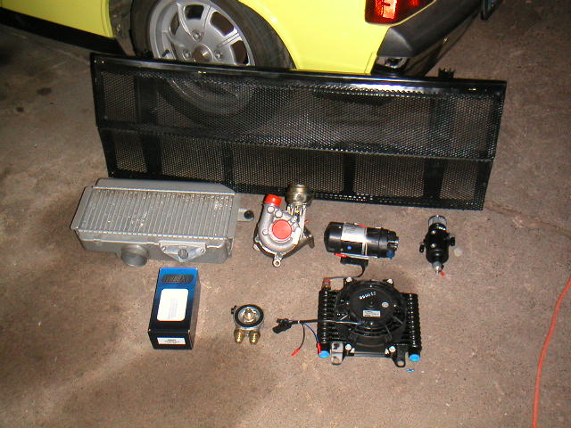
|
   |

 
|
| Chris Pincetich |
Dec 25 2006, 04:23 PM
Post
#2
|
|
B-) Group: Members Posts: 2,082 Joined: 3-October 05 From: Point Reyes Station, CA Member No.: 4,907 Region Association: Northern California |
Sweet! I like the the header collector mount/interface and that you don't plan to cut anywhere other than the tin. Maybe even use the J tube hole in the tin? Not really the best location though...Good luck!
|
|
|
|
| ottox914 |
Jan 8 2007, 02:19 PM
Post
#3
|
|
The glory that once was. Group: Members Posts: 1,302 Joined: 15-December 03 From: Mahtomedi, MN Member No.: 1,438 Region Association: Upper MidWest |
Now that the holidays have come and gone, and my real job is a bit slower, more time is availible to hang out in the shop. Here are a few mock up photos of the ITB hats, intercooler location, and boost gauge. The angle of the charge lines coming off the hats looks a bit extreme, but some of that is the perspective of the photo. The WRX intercooler has 2 outlets on the underside of the end tank, one will go left, one to the right, and these will drop down an inch or so from the IC, so they will end up lining up fairly well with the ITB hats. Next monday I have a couple friends coming over, and I'm taking the day off to make some time on this project. Look for more photos and progress reports then-
Photos were too big- will re-shoot and add them later tonight. |
|
|
|
| Mark Henry |
Jan 8 2007, 03:20 PM
Post
#4
|
|
that's what I do! Group: Members Posts: 20,065 Joined: 27-December 02 From: Port Hope, Ontario Member No.: 26 Region Association: Canada |
Very cool David. We're thinking along the same lines...
I'm thinking about a DTM set-up for more clearance, with the SDS and 94mm Nickies with cima b pistons. We should compare notes and maps as we go. Post some pics of the intercooler outlets please. Take a look at iamchappy's turbo /6 for some ideas on how to plumb the rear end turbo oil return...I think he had to make a small catch tank. What's the Garrett VNT off of? how much? |
|
|
|
| GS Guy |
Jan 8 2007, 04:23 PM
Post
#5
|
|
Member Group: Members Posts: 243 Joined: 8-July 04 From: Columbia, MD Member No.: 2,325 Region Association: North East States |
Cool project David!
You do know the two openings on the one side of the intercooler are inlets right? The large 2-3/4" round opening the outlet? I don't know if it makes any difference to run it backwards?? Maybe have to reposition the blow off valve to the inlet side? Normally, the WRX runs a couple of cast elbost that bolt up to the 2 openings, which connect to a Y pipe and then to the turbo outlet. I like the project though! DO IT! Jeff |
|
|
|
| Mueller |
Jan 8 2007, 04:24 PM
Post
#6
|
|
914 Freak! Group: Members Posts: 17,155 Joined: 4-January 03 From: Antioch, CA Member No.: 87 Region Association: None |
QUOTE(ottox914 @ Jan 8 2007, 12:19 PM)  Now that the holidays have come and gone, and my real job is a bit slower, more time is availible to hang out in the shop. Here are a few mock up photos of the ITB hats, intercooler location, and boost gauge. The angle of the charge lines coming off the hats looks a bit extreme, but some of that is the perspective of the photo. The WRX intercooler has 2 outlets on the underside of the end tank, one will go left, one to the right, and these will drop down an inch or so from the IC, so they will end up lining up fairly well with the ITB hats. Next monday I have a couple friends coming over, and I'm taking the day off to make some time on this project. Look for more photos and progress reports then- Photos were too big- will re-shoot and add them later tonight. no need to re-shoot, "google" Irfanview, it is a free and simple photoeditor.. |
|
|
|
| ottox914 |
Jan 8 2007, 06:45 PM
Post
#7
|
|
The glory that once was. Group: Members Posts: 1,302 Joined: 15-December 03 From: Mahtomedi, MN Member No.: 1,438 Region Association: Upper MidWest |
Here come some pics- being only slightly more computer literate that a rock, I didn't realize I had a re-size function availible with what was already on the laptop. Oh well, live and learn. Maybe this is a good advertisement for SDS. So easy I can do it!
So far as progress, spent the afternoon finishing up on cleaning and lubing up the door locks and internal door mechanisms. Had one of the plastic odd shaped thingies give way on the driver door, so it seemed a good time to go thru both doors. Got the ITB "hats" placed, and have the intercooler perched on some boxes to find a good location. Tomorrow is a big road day for me, but wednesday should be a soft day at the real job, my wife is out of town that PM, so I should be able to work on the car, eat pizza, and toss back a few beers, all with great success, so expect more pics late wed. I've included some photos of the L and R sides with the ITB hats and intercooler. The perspective of the photo makes the 2" inlet to the hats look like its angled way down and away. In reality, when you figure the drop off the intercooler for the new charge pipes, things should line up pretty well for a dual hump 90 degree elbow, 2 of which are on order. The boost gauge is from... a subaru. Why I haven't just done the whole subie swap is beyond me- the reason for this gauge is its small size, and its case is rubber, so I can trim the back of the gauge off 1/4 inch or so, and it'll fit the short space avalible between the dash and top of the steering collum, with out overhanging and getting in the way of the steering wheel. Attached image(s) 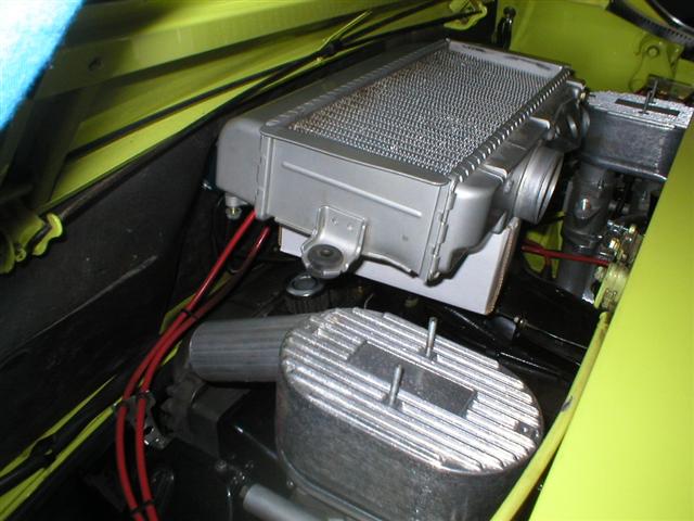 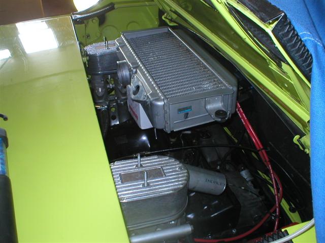 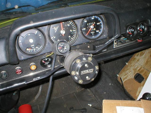
|
|
|
|
| ottox914 |
Jan 8 2007, 06:47 PM
Post
#8
|
|
The glory that once was. Group: Members Posts: 1,302 Joined: 15-December 03 From: Mahtomedi, MN Member No.: 1,438 Region Association: Upper MidWest |
Here's a couple of the GT lid with the goodies underneath it. I'll post more answers to ?'s after dinner- Mrs Me has called up, its ready, so, gotta go-
Attached image(s) 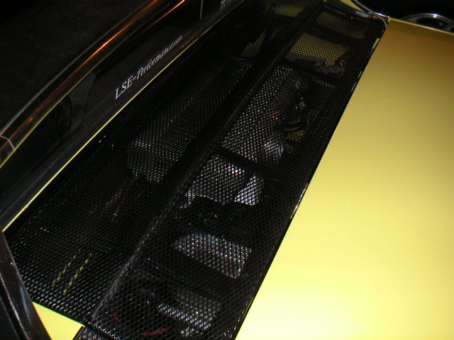 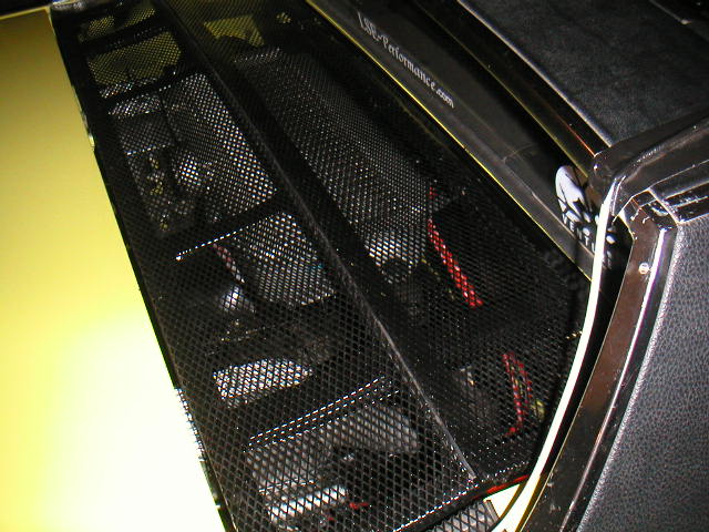
|
|
|
|
| Crazyhippy |
Jan 8 2007, 07:36 PM
Post
#9
|
|
Insert witty comment here... Group: Members Posts: 1,659 Joined: 28-July 05 From: Home of the Coyotes, AZ Member No.: 4,493 Region Association: None |
QUOTE(ChrisNPDrider @ Dec 25 2006, 02:23 PM) Sweet! I like the the header collector mount/interface and that you don't plan to cut anywhere other than the tin. Maybe even use the J tube hole in the tin? Not really the best location though...Good luck! Now that is a Neat thought.... Spin the intercooler 180* from where you have it now, and move it back 4" or so. Make the outlets from the intercooler go due left and right and into the sides of the ITBs. I'm interested in the results you get. BJH |
|
|
|
| ottox914 |
Jan 8 2007, 10:54 PM
Post
#10
|
|
The glory that once was. Group: Members Posts: 1,302 Joined: 15-December 03 From: Mahtomedi, MN Member No.: 1,438 Region Association: Upper MidWest |
Mark Henry- Why DTM, besides your selling Jakes parts in Canada? Won't that be a higher profile, in terms of the overall engine? It would give you some more room up in front of the engine if you were thinking of some header/turbo mount up there. I had some thoughts in that direction, a flat fan over the engine, either electric or crank driven, intercooler mounted on top of that, ITB's, and a turbo mounted in front of the motor, just never got around to getting serious about that wild plan.
We can probably share some SDS notes, but depending on your cam, and turbo, this may or may not be helpful at all. I'll shoot and post some intercooler shots tomorrow night. I've talked to Chappy a bit, and done some research of my own. The catch can is more to have a spot for the remaining oil in the lines to the turbo to go, once you shut down, as the turbo spins down, there will be some residual pressure in those lines, and when the scavenge pump shuts off, there is no where for that oil to go, as the turbo spins down, so it can seep past the seals and give you a "puff" at start up, and possibly shorten the seal life. Longer lines between the turbo outlet and scavenge pump will allow more volume for this oil to fill, so long as it doesn't have to go up hill. I plan to add a small sump to my system anyway. I had an Aerocharger brand (no longer in business) VNT turbo on a ford focus, and was spoiled with the response. I researched availible VNT's and found the VW TDI's to use one of 2 different models, the VNT-15 and VNT-17. The compressor map of the -15 was better suited to what I wanted to do, so I found a NIB turbo on evil bay a couple yrs ago, snatched it up, and kept it on the shelf till I was ready to do this. Don't recall the $$$ exactally, as its been several yrs. 3-400 seems to ring a bell though. GS guy- yes, I an using the IC "backwards", but airflow is airflow. If you snoop around the turbo topic, and specifically air to water intercoolers, you'll find guys taking ford Tbird IC's, jacketing them, and turning them into air to water systems. With all this going on, reversing the air flow doesn't scare me off of the utility and packaging of this IC with 3 holes in it. As I'm going to try to mount the IC as close to the GT lid as possible, I'll be making a block off plate for the subi blow off valve mount, and adding it in line between the turbo and IC. It could still mount on the IC if I wanted it to, or I could buy 2 BOV's and mount one in each ITB hat. That might be cool, but why buy 2 when 1 will do? This is not a bling-mobile honda we're talking about here... Mr CrazyHippy- Using the hole in the engine tin for the "J" tube passed thru my mind also, but with the ITB's more to the rear of the engine bay, the packaging of the parts I had, things just worked out better this way. The charge air from the turbo will come up under the trunk, and thru the back verticle engine tin, where a 90 degree elbow will bring it up towards the IC at about a 45 degree angle, and another 90 degree elbow will take it into the back of the IC. I'm not the most visual person in the world, so if that was not explained well enough, the photos will make more sense once I get that far. This is sort of the inspiration for this little adventure: www.ststurbo.com. I will be adding a pressure switch after the scavenge pump, and running that to the parking brake light on the dash. I put the BMW 320 front calipers on my car, and moved my fronts to the back, and as such, have no parking brake anyway, might as well use that big light for something. |
|
|
|
| Crazyhippy |
Jan 8 2007, 11:00 PM
Post
#11
|
|
Insert witty comment here... Group: Members Posts: 1,659 Joined: 28-July 05 From: Home of the Coyotes, AZ Member No.: 4,493 Region Association: None |
That is a perfectly fine description. Looks like fun...
BJH |
|
|
|
| Mark Henry |
Jan 10 2007, 08:23 AM
Post
#12
|
|
that's what I do! Group: Members Posts: 20,065 Joined: 27-December 02 From: Port Hope, Ontario Member No.: 26 Region Association: Canada |
QUOTE(ottox914 @ Jan 8 2007, 11:54 PM) Mark Henry- Why DTM, besides your selling Jakes parts in Canada? Won't that be a higher profile, in terms of the overall engine? It would give you some more room up in front of the engine if you were thinking of some header/turbo mount up there. I had some thoughts in that direction, a flat fan over the engine, either electric or crank driven, intercooler mounted on top of that, ITB's, and a turbo mounted in front of the motor, just never got around to getting serious about that wild plan. We can probably share some SDS notes, but depending on your cam, and turbo, this may or may not be helpful at all. I have the DTM mocked up in the car now, the amount of room in front of the engine is huge! I should be able to mount the turbo in front high enough to drain into the sump, while building the tin so that it is still technically under the car...I may even have enough room to do the same with the intercooler. I'd have to feed it via a scoop under the car. Our fuel maps will be different but other points in the map may be the same. |
|
|
|
| ottox914 |
Jan 10 2007, 10:53 PM
Post
#13
|
|
The glory that once was. Group: Members Posts: 1,302 Joined: 15-December 03 From: Mahtomedi, MN Member No.: 1,438 Region Association: Upper MidWest |
Not alot of turbo specific progress today, but some photos. Work kept getting in the way, and the shop was freezing cold- I could see my breath inside! Oh well, the owner is letting my car spend the winter there for free, and if he has no work for a day in the shop and cuts the heat, who am I to complain?
Today I picked up some aluminum stock to mount the intercooler, and got the thermostat/sandwich plate adaptor installed, so I can mount and run lines to the oil cooler. Below is a photo of the underside of the WRX intercooler, showing the 2 outlets. Next are a couple of photos of the thermostat/sandwich plate adaptor. Yes, doing one of Jakes full flow systems would be better, and yes, doing AN fittings and hose would be cooler, but this is only phase 2, remember? The $$$ I save by not dropping the engine and doing Jakes full flow, or not doing the braided/AN stuff will go along ways towards some of the special fabrication I can't do myself. Attached image(s) 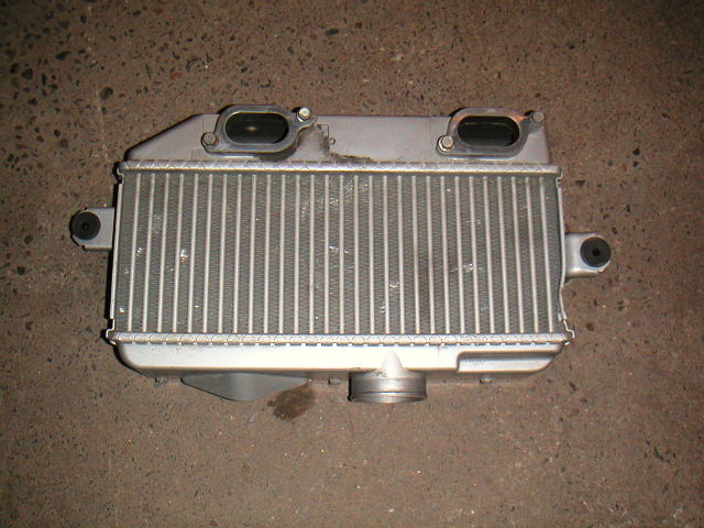 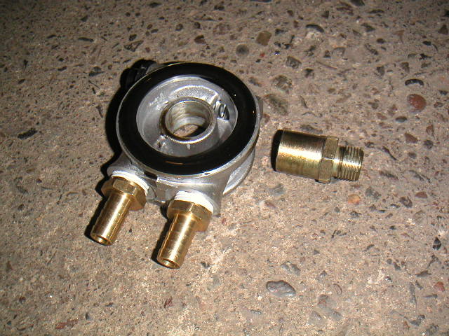 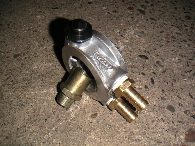 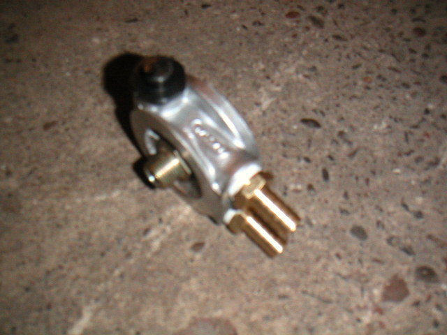
|
|
|
|
| ottox914 |
Jan 10 2007, 10:58 PM
Post
#14
|
|
The glory that once was. Group: Members Posts: 1,302 Joined: 15-December 03 From: Mahtomedi, MN Member No.: 1,438 Region Association: Upper MidWest |
After removing the old filter and draining the oil, I pre-lubed the new filter, oiled the rubber gasket in the adaptor, slid it over the center piece, and using a 1" socket, tightened the center piece to the existing oil filter location on the block. After adding a new Mahle filter, you'll see it doesn't even extend below the engine mounting bar. The thermostat adaptor came from: BAT in Florida. Here's the rest of the photos-
And- anyone using this thermostat/adaptor know which is the line out, and line in for the oil flow? There were no directions in the box. Does it matter? The instructions for the cooler I'll be using note a specific in and out for that part, I just wanted to be sure to match everything up correctly. On to the photos- Attached image(s) 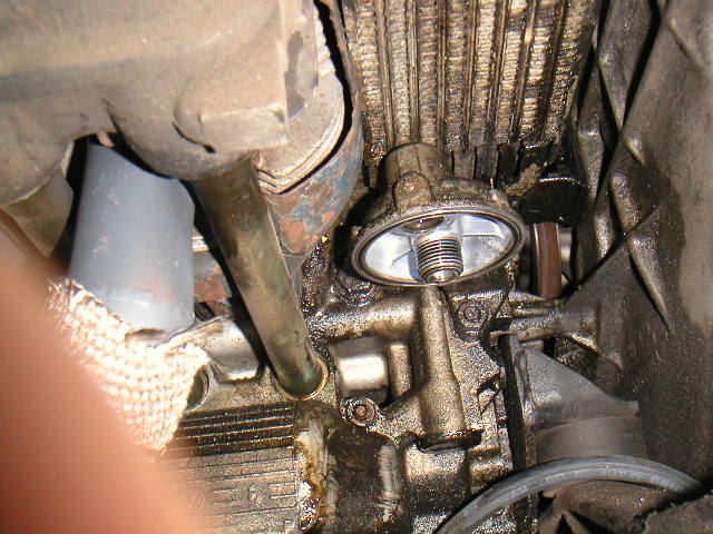 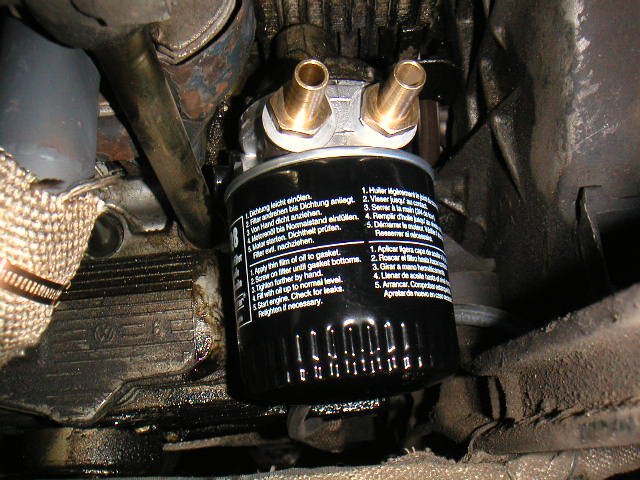
|
|
|
|
| ottox914 |
Jan 13 2007, 08:36 PM
Post
#15
|
|
The glory that once was. Group: Members Posts: 1,302 Joined: 15-December 03 From: Mahtomedi, MN Member No.: 1,438 Region Association: Upper MidWest |
1-16-07 updates- got the oil cooler installed- sort of. I'll be taking it out to add the fittings and connect the hoses, but here's how it went:
first photo is a hard to cut up trunk, but then again, I put holes in it for the rear sway bar, so whats the deal with 4 more? second photo is 4 perfectly sized holes, courtesy of photo three, the unibit! *I went back and forth from under the car to in the trunk at least a half a dozen times to decide where to drill. I then laid the cooler out in the trunk, marked for holes, drilled 2 sizes of pilot hole, then had at it with the unibit. In retrospect, I should have moved things to the outside of the car 1/2 an inch or so, the "bumps" in the trunk carpet would have been less if I had put all the nuts in the low spots of the trunk. Oh well, whats done is done, and with the rubber insulation mat and carpet in, you don't really notice the bumps that much. photo 4 is the cooler, wired up. you need to attach a wire from the thermostat to the fan motor, attach the other wire to the thermostat to a (+) with 15 amp fuse, and attach the other wire from the fan motor to ground. The ground will be going back by the transmission, and attaching at the braded ground strap. the (+) will be going to the back of the verticle engine tin, where I will be installing a relay to power the fan and scavenge pump. I'll be moving my "hot start" relay to that location as well, so there will be 2 side by side. Attached image(s) 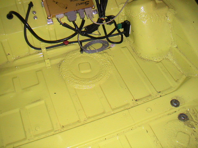 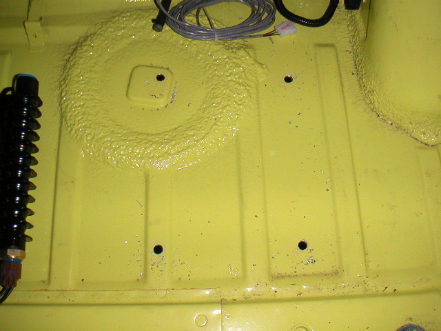 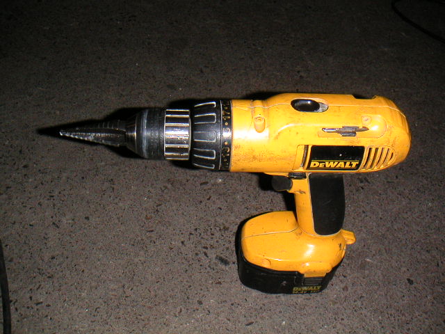 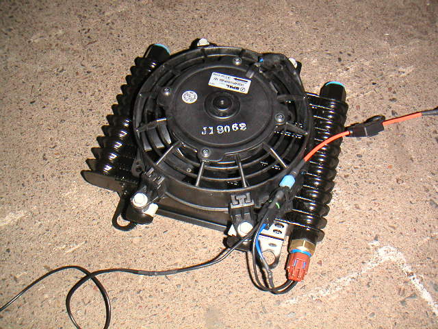
|
|
|
|
| ottox914 |
Jan 13 2007, 08:38 PM
Post
#16
|
|
The glory that once was. Group: Members Posts: 1,302 Joined: 15-December 03 From: Mahtomedi, MN Member No.: 1,438 Region Association: Upper MidWest |
Mounting the cooler. The threaded rod went thru the trunk, with a nut, lock washer, and flat washer inside the trunk. I put a flat, lock, and nut up the rod under the trunk, and tightened it all up. Those new ratcheting wrenches sure made this easy.
In the second photo, I have added some cheep hose over the threaded rod and nut, hiding it all, cleaning up the look a little, and getting ready for photo 3. In photo 3, I have added a washer and nut, to tighten up the hose. I tightened the nut so that each rod has the same length of threads showing. I then added 1/2 inch of hose over the nut. I then added the cooler, 1/2 inch more hose, and a washer and nut to finsh it off. Photo 4 shows the cooler mounted. I'm hoping that due to the cooler holes being much bigger than the threaded rod, and that the mounts are sandwiched between 1/2 inch of rubber hose on each side, that this will allow for a sort of shock mounting to allow a little flexability in the mounts, should the need for some flex arrise, thus preventing the cooler itself from flexing and cracking/leaking. I still have to remove the cooler to attach the power/fuse to the temp sensor, attach the barbed hose fitings, connect the lines, and I have some lock nuts to put on after the last bit of hose and washer, to try to keep everything togather with out having to really crank it down- I couldn't see how I could keep my shock mounting and tighten/compress everything enough to use a lock washer on the bottom, as I did on the top. Monday I have my friends Lee and Dave-o, the fearless fabricator coming over for the day. Hopefully I'll have photos of the intercooler mounted, boost gauge mounted and hooked up, and maybe some intercooler piping started if we're lucky. We'll see how it goes and report back tuesday. Attached image(s) 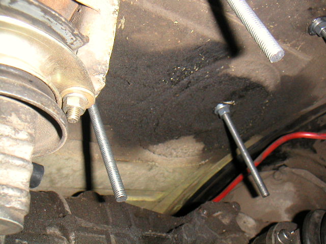 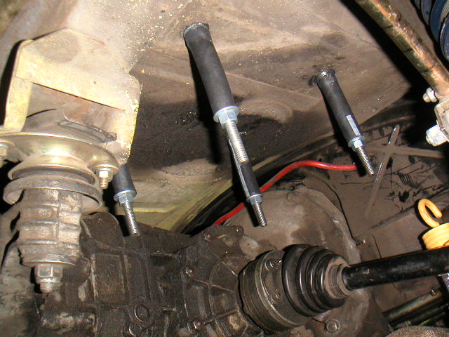 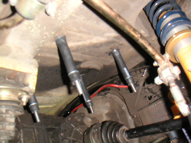 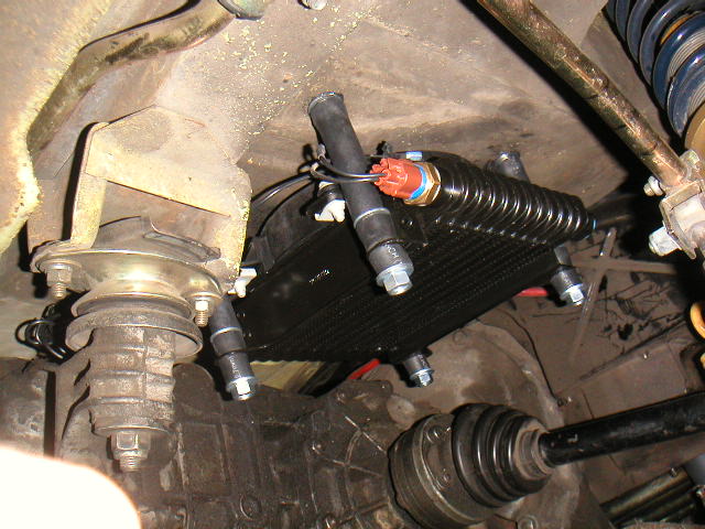
|
|
|
|
| Andyrew |
Jan 13 2007, 09:29 PM
Post
#17
|
|
Spooling.... Please wait Group: Members Posts: 13,380 Joined: 20-January 03 From: Riverbank, Ca Member No.: 172 Region Association: Northern California |
those are really long threads...
Get 1in long one's.. not 5!!! The rest of it looks good! |
|
|
|
| Crazyhippy |
Jan 14 2007, 12:52 AM
Post
#18
|
|
Insert witty comment here... Group: Members Posts: 1,659 Joined: 28-July 05 From: Home of the Coyotes, AZ Member No.: 4,493 Region Association: None |
have to space the cooler away from the floor for airflow....
Nicely done. BJH |
|
|
|
| ottox914 |
Jan 14 2007, 07:44 AM
Post
#19
|
|
The glory that once was. Group: Members Posts: 1,302 Joined: 15-December 03 From: Mahtomedi, MN Member No.: 1,438 Region Association: Upper MidWest |
QUOTE(Crazyhippy @ Jan 13 2007, 10:52 PM) have to space the cooler away from the floor for airflow.... Nicely done. BJH I was looking at the picture last night thinking the same thing. When I take it appart to add the hose fittings, I'll cut some 1" hose "spacers" and put them in place of the first 1/2" bit of hose thats on there now. I'll get a thin rubber grommit to lay over the bottom washer, then add the nylock nuts, and I'll buy a little depth that way, and still hopefully keep a little of my shock mounting. That was my plan from the start- being able to adjust the depth of the fan as I go, since I didn't really know how it'd all fit togather. The fan is designed as a "puller", but still it should have more air space than it does. |
|
|
|
| Dave-O |
Jan 14 2007, 10:20 AM
Post
#20
|
|
Is winter done yet? Group: Members Posts: 511 Joined: 26-August 03 From: Minneapols, MN Member No.: 1,082 |
Looks good Dave! What kind of stock did you get to mount the intercooler, 1"x1" square? We'll be sure to spend some time in the McMaster Carr catalog for prettier studs.
See you tomorrow, |
|
|
|
|
1 User(s) are reading this topic (1 Guests and 0 Anonymous Users)
0 Members:

|
Lo-Fi Version | Time is now: 30th June 2026 - 02:10 PM |
Invision Power Board
v9.1.4 © 2026 IPS, Inc.