|
|
|
Porsche, and the Porsche crest are registered trademarks of Dr. Ing. h.c. F. Porsche AG.
This site is not affiliated with Porsche in any way. Its only purpose is to provide an online forum for car enthusiasts. All other trademarks are property of their respective owners. |
|
|

  |

| yarin |
 Apr 5 2007, 07:19 PM Apr 5 2007, 07:19 PM
Post
#1
|
|
'14-X'in FOOL  Group: Members Posts: 988 Joined: 13-May 03 From: Guttenberg, NJ Member No.: 693 Region Association: North East States |
I datalogged a few runs and found the issue to my random ignition hitch. Previously I thought the tach signal was dropping out, but you certainly cant argue with this data...
My MSII is grounded to one of the tranny bolts. The tranny groud strap was just changed and cleaned up. +12V is connected to the battery cutoff switch (I think where one of the terminals where the alternator plugs in, i'll double check). Is this OK? A voltage spike (both up and down) causes Pulse Width to max out, maxing out injector duty cycle, resulting in a quick cough. This occurs once in a while, sometimes every 30 seconds, sometimes not for a few minutes. Voltage never spikes at idle, only when driving at mid rpm. Could it be a bad connection? (then i would assume the spike would be unidirectional). Bad voltage regulator on alternator? The battery charges fine, normal operating voltage is ok. These are about 1/10th sec samples from datalogging: 13.4 13.5 13.3 13.3 21.5 13.9 13.5 13.5 13.3 13.9 13.6 18.6 14.8 13.9 13.9 13.7 14 14 13.7 13.5 8 13.2 13.5 Any thoughts? Where my MS experts at? Thanks 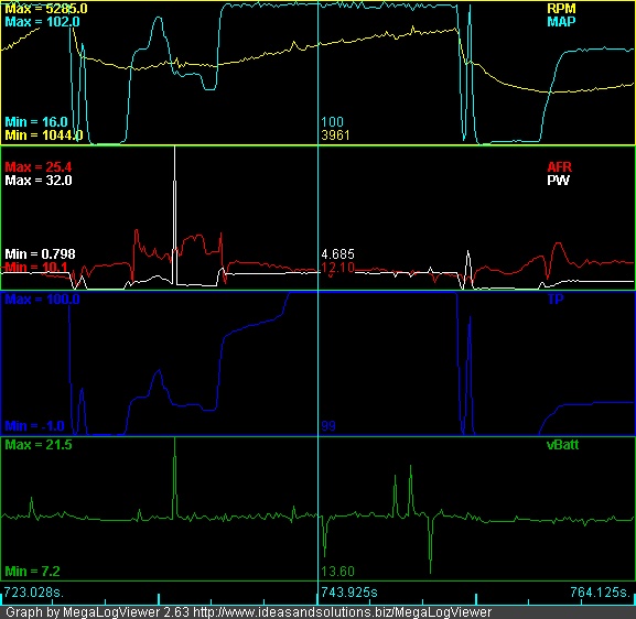 Attached File(s)  datalog200704011555_voltage_glitch.xls ( 224.4k )
Number of downloads: 43
datalog200704011555_voltage_glitch.xls ( 224.4k )
Number of downloads: 43 |
   |

 
|
| bd1308 |
Apr 5 2007, 07:47 PM
Post
#2
|
|
Sir Post-a-lot Group: Members Posts: 8,020 Joined: 24-January 05 From: Louisville,KY Member No.: 3,501 |
I dunno, but I am just so excited to have MS running on my 914 that I can hardly contain myself
Those logs are neat! I would choose more DIRECT power connections |
|
|
|
| davep |
Apr 5 2007, 08:09 PM
Post
#3
|
|
914 Historian Group: Benefactors Posts: 5,151 Joined: 13-October 03 From: Burford, ON, N0E 1A0 Member No.: 1,244 Region Association: Canada |
Almost looks like the alternator is being disconnected. It is usually called a load dump. Those high voltages are very bad. However, other than fixing the root cause, there are special diodes that are designed for this application. I'd have to look up the part # since I haven't designed them into a circuit recently. I'd still look to see why the voltage is doing that. It is very hard on the entire system including radios and lights.
|
|
|
|
| bd1308 |
Apr 5 2007, 08:23 PM
Post
#4
|
|
Sir Post-a-lot Group: Members Posts: 8,020 Joined: 24-January 05 From: Louisville,KY Member No.: 3,501 |
Myabe bad wiring?
|
|
|
|
| yarin |
Apr 5 2007, 08:23 PM
Post
#5
|
|
'14-X'in FOOL Group: Members Posts: 988 Joined: 13-May 03 From: Guttenberg, NJ Member No.: 693 Region Association: North East States |
QUOTE(davep @ Apr 5 2007, 10:09 PM)  Almost looks like the alternator is being disconnected. It is usually called a load dump. Those high voltages are very bad. However, other than fixing the root cause, there are special diodes that are designed for this application. I'd have to look up the part # since I haven't designed them into a circuit recently. I'd still look to see why the voltage is doing that. It is very hard on the entire system including radios and lights. A disconnect would lead me to think i'd only see down spikes, but i'm seeing spikes up to 20VDC as well. How can I check the alternator? I doubt these spikes will show up on a bench test with a standard voltmeter or automotive store test. I'm not worried about the rest of the car except my Megasquirt and Wideband O2 since I have no radio and never use the lights (IMG:style_emoticons/default/smile.gif) What type of diode setup are you referring to? Additional to the voltage regulator? |
|
|
|
| davep |
Apr 5 2007, 08:26 PM
Post
#6
|
|
914 Historian Group: Benefactors Posts: 5,151 Joined: 13-October 03 From: Burford, ON, N0E 1A0 Member No.: 1,244 Region Association: Canada |
Sorry, I think it is the battery disconnected. Look for poor ground connection, or perhaps a bad battery with intermittent internal opens.
|
|
|
|
| yarin |
Apr 5 2007, 08:31 PM
Post
#7
|
|
'14-X'in FOOL Group: Members Posts: 988 Joined: 13-May 03 From: Guttenberg, NJ Member No.: 693 Region Association: North East States |
It just so happens the PW spike associated with voltage spike has been addressed in the latest firmware:
Version 2.310, 2.320, 2.330, 2340, 2.350, 2.360 Fixed bug in ASE logic;set PW=0 in RevLimit mode;gcc compatibility changes; fixed bug in spare port hysteresis; changed some defaults; fixed bug in masking of TimerIn interrupts for dt/2; limited pw_open in case of battery spikes. As a bandaid i'll try the new code so my PW doesn't spike to 32ms. However, i believe the alternator might be my issue as opposed to an intermittent connection... I'll check for loose connections and metal filings around the relay box area. |
|
|
|
| davep |
Apr 5 2007, 08:37 PM
Post
#8
|
|
914 Historian Group: Benefactors Posts: 5,151 Joined: 13-October 03 From: Burford, ON, N0E 1A0 Member No.: 1,244 Region Association: Canada |
Look for loose connections on the regulator and the relay panel. No matter the cause, the voltage spikes are bad news and should be fixed. As I say, there are diodes designed to protect from 'load dumps'. Motorola part MR2535L from memory.
|
|
|
|
| Twystd1 |
Apr 5 2007, 08:39 PM
Post
#9
|
|
You don't want to know... really..... Group: Members Posts: 2,514 Joined: 12-September 04 From: Newport Beach, California Member No.: 2,743 |
We had a discussion at the club site on a ECU issue on Randals car.
I have see this same stuff happen on several aftermarket EFI systems. It is all about grounding issues and spurious signals going into the ecu by means of high voltage circuit. (read: plug wires and coil) Simply using the wrong spark plugs (resistor VS non-resisitor) can make this stuff happen. So can resistor wires VS solid core wires. I just plagiarized this from DNHunt without his permission. I hope he doesn't mind. I'm not sure if this will help but, I had a bunch of problems with my car with EM noise from the ignition. Changing to resistor plugs cleaned it up. Routing sensors wiring away from sparkplug wires can help and sheilding cables can help especially if the tach signal to the ECU is weak. I use a VR sensor and signal strength is very weak and it must be sheilded. Another thing, if you are using sheilded cable only ground the end at the ECU and ground it to the same ground as the ECU. This helps prevent ground loops. Keep the ground points to a minimum. Some sensors ground to the engine case and you can't do anything about those but, try to bring all grounds back to the ECU if possible. It may seem simple to ground things like the TPS and MAP sensor to the nearest point but, don't do it, these are referenced voltages. Try not to have extra unused wires in your harness as these may increase noise. Kind of a ramble but, I had to learn all of these things the hard way." So there is some more food for thought... Clayton |
|
|
|
| yarin |
Apr 5 2007, 11:22 PM
Post
#10
|
|
'14-X'in FOOL Group: Members Posts: 988 Joined: 13-May 03 From: Guttenberg, NJ Member No.: 693 Region Association: North East States |
I'll try to route the signal cables away from the coil and spark plug wires. I think I bought Magnecore wires a while ago, i'll have to check. Are they solid or resistor based?
I know my electrical connections are solid, I tied all the sensors to a common grounding bus. My tach wire is shielded to ground too. What configuration should I connect the MR2535L diode in? Series with the +12V line. Parallel to ground? I attached the datasheet. Thanks! QUOTE(Twystd1 @ Apr 5 2007, 10:39 PM) We had a discussion at the club site on a ECU issue on Randals car. I have see this same stuff happen on several aftermarket EFI systems. It is all about grounding issues and spurious signals going into the ecu by means of high voltage circuit. (read: plug wires and coil) Simply using the wrong spark plugs (resistor VS non-resisitor) can make this stuff happen. So can resistor wires VS solid core wires. I just plagiarized this from DNHunt without his permission. I hope he doesn't mind. I'm not sure if this will help but, I had a bunch of problems with my car with EM noise from the ignition. Changing to resistor plugs cleaned it up. Routing sensors wiring away from sparkplug wires can help and sheilding cables can help especially if the tach signal to the ECU is weak. I use a VR sensor and signal strength is very weak and it must be sheilded. Another thing, if you are using sheilded cable only ground the end at the ECU and ground it to the same ground as the ECU. This helps prevent ground loops. Keep the ground points to a minimum. Some sensors ground to the engine case and you can't do anything about those but, try to bring all grounds back to the ECU if possible. It may seem simple to ground things like the TPS and MAP sensor to the nearest point but, don't do it, these are referenced voltages. Try not to have extra unused wires in your harness as these may increase noise. Kind of a ramble but, I had to learn all of these things the hard way." So there is some more food for thought... Clayton Attached File(s)  MR2535L_D.pdf ( 62.77k )
Number of downloads: 27
MR2535L_D.pdf ( 62.77k )
Number of downloads: 27 |
|
|
|
| mightyohm |
Apr 6 2007, 02:11 AM
Post
#11
|
|
Advanced Member Group: Benefactors Posts: 2,277 Joined: 16-January 03 From: Seattle, WA Member No.: 162 Region Association: Pacific Northwest |
If the battery gets disconnected intermittently it will cause positive voltage spikes like you see there. The regulator will go nuts due to the open circuit and cause the alternator to produce the highest possible voltage. I had similar problems when I first installed my Megasquirt, and I found that a new voltage regulator solved the problem in my case. The old mechanical one was sticking and causing the system voltage to go up to 18V occasionally.
|
|
|
|
| mightyohm |
Apr 6 2007, 02:18 AM
Post
#12
|
|
Advanced Member Group: Benefactors Posts: 2,277 Joined: 16-January 03 From: Seattle, WA Member No.: 162 Region Association: Pacific Northwest |
I don't think the diode will solve your problems. It may be a bandaid and reduce the pulsewidth issues, but you need to fix what is causing the problems in the first place. I see you also have voltage drops down to 7V which is bad and probably caused by the same issue.
|
|
|
|
| DEC |
Apr 6 2007, 05:36 AM
Post
#13
|
|
Senior Member Group: Members Posts: 630 Joined: 10-November 05 From: Rehburg Member No.: 5,104 Region Association: Germany |
QUOTE(yarin @ Apr 5 2007, 05:19 PM) This looks like a flapping voltage regulator (is this correct US name for it?) The old mechanical regulators are very slow in her reactions, so you see up and down peaks in your sample. If you use an electronical regulator I think you will see a straight line with small peaks. What kind of regulator you used? |
|
|
|
| yarin |
Apr 7 2007, 09:21 AM
Post
#14
|
|
'14-X'in FOOL Group: Members Posts: 988 Joined: 13-May 03 From: Guttenberg, NJ Member No.: 693 Region Association: North East States |
How can I tell what type of regulator i'm using (mechanical vs. electrical)? What is stock for a '73 motor?
Looking at Pelican Parts I gather that the voltage regulator is on the relay board, is this correct? Is this http://www.pelicanparts.com/catalog/shopca..._ELchrg_pg1.htm a mechanical or electrical regulator? Since it's on the relay board it must be electrical, right? BTW - I updated to the latest MS 2.6 firmware and the pulse width pikes were significantly reduced, I can't really sense a spike anymore. The MS guys are really damn bright! However the voltage spike is still there... Thanks |
|
|
|
| crash914 |
Apr 7 2007, 10:29 AM
Post
#15
|
|
its a mystery to me Group: Members Posts: 1,826 Joined: 17-March 03 From: Marriottsville, MD Member No.: 434 Region Association: MidAtlantic Region |
Sorry to Hijack... but related..
Is there a conversion from the mechanical regulator to an electronic voltage regulator? Is there a plug and play solution or do I have to splice wires? hijack over... |
|
|
|
| Aaron Cox |
Apr 7 2007, 11:48 AM
Post
#16
|
|
Professional Lawn Dart Group: Retired Admin Posts: 24,541 Joined: 1-February 03 From: OC Member No.: 219 Region Association: Southern California |
run a GM one wire alternator (IMG:style_emoticons/default/smile.gif) internally regulated and cheap
a guy over on STF showed how to do it on a type 4 |
|
|
|
| yarin |
Apr 7 2007, 05:53 PM
Post
#17
|
|
'14-X'in FOOL Group: Members Posts: 988 Joined: 13-May 03 From: Guttenberg, NJ Member No.: 693 Region Association: North East States |
QUOTE(crash914 @ Apr 7 2007, 12:29 PM) Sorry to Hijack... but related.. Is there a conversion from the mechanical regulator to an electronic voltage regulator? Is there a plug and play solution or do I have to splice wires? hijack over... Are the stock regulators mechanical or electrical? |
|
|
|
| DEC |
Apr 8 2007, 09:23 AM
Post
#18
|
|
Senior Member Group: Members Posts: 630 Joined: 10-November 05 From: Rehburg Member No.: 5,104 Region Association: Germany |
The stock regulator is mechanical (IMG:style_emoticons/default/barf.gif) , Hella offers an eletronical that's
plug and play. The Hella number is 5DR 004 243-041 14V |
|
|
|
| DEC |
Apr 8 2007, 09:33 AM
Post
#19
|
|
Senior Member Group: Members Posts: 630 Joined: 10-November 05 From: Rehburg Member No.: 5,104 Region Association: Germany |
This is also an electronical regulator from Bosch thats PP offers
on the pic you can see the transistor  |
|
|
|
| McMark |
Apr 8 2007, 10:13 AM
Post
#20
|
|
914 Freak! Group: Retired Admin Posts: 20,179 Joined: 13-March 03 From: Grand Rapids, MI Member No.: 419 Region Association: None |
(IMG:style_emoticons/default/agree.gif) get the electronic regulator. It 'bolts' right in. 10 minute install.
|
|
|
|
|
1 User(s) are reading this topic (1 Guests and 0 Anonymous Users)
0 Members:

|
Lo-Fi Version | Time is now: 25th May 2024 - 07:25 PM |
Invision Power Board
v9.1.4 © 2024 IPS, Inc.