|
|
|
Porsche, and the Porsche crest are registered trademarks of Dr. Ing. h.c. F. Porsche AG.
This site is not affiliated with Porsche in any way. Its only purpose is to provide an online forum for car enthusiasts. All other trademarks are property of their respective owners. |
|
|

  |

| Jeff Hail |
 Nov 29 2009, 01:10 AM Nov 29 2009, 01:10 AM
Post
#421
|
|
Senior Member  Group: Members Posts: 1,141 Joined: 3-May 07 From: LA/ CA Member No.: 7,712 |
Hood fits perfect. Only the best will do.
Attached thumbnail(s) 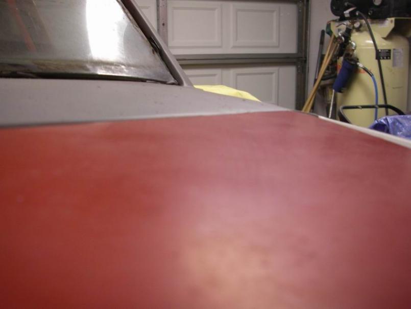
|
   |

 
|
| Jeff Hail |
Dec 1 2009, 12:36 AM
Post
#422
|
|
Senior Member Group: Members Posts: 1,141 Joined: 3-May 07 From: LA/ CA Member No.: 7,712 |
Did ya notice the hinges? Weight Watchers for Fat Girls style.
Attached thumbnail(s) 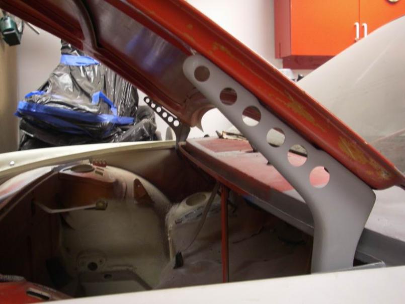
|
|
|
|
| Jeff Hail |
Dec 19 2009, 12:09 AM
Post
#423
|
|
Senior Member Group: Members Posts: 1,141 Joined: 3-May 07 From: LA/ CA Member No.: 7,712 |
Not planning to have any ventilation blower so no need for the cowl intake anymore. Notice the bulkhead duct (oval) holes are gone too.
Yes that is filler dust you see (holy crap he actually finally used some mud) Attached thumbnail(s) 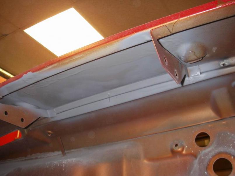 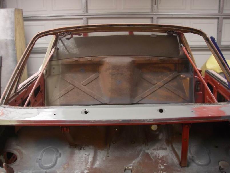
|
|
|
|
| Jeff Hail |
Dec 27 2009, 03:30 AM
Post
#424
|
|
Senior Member Group: Members Posts: 1,141 Joined: 3-May 07 From: LA/ CA Member No.: 7,712 |
Forward bulkhead compartment denuded of seam sealer. Stripped to bare metal looking for rust. I did find some minor surface rust scale where the two bolts secure the hood lock cylinder housing. Chemical metal prep was all that was needed. Self etching primer applied. Very clean.
Notice the brake fluid bottle bracket and hood spring brackets are removed along with the cowl vent intake. Attached thumbnail(s) 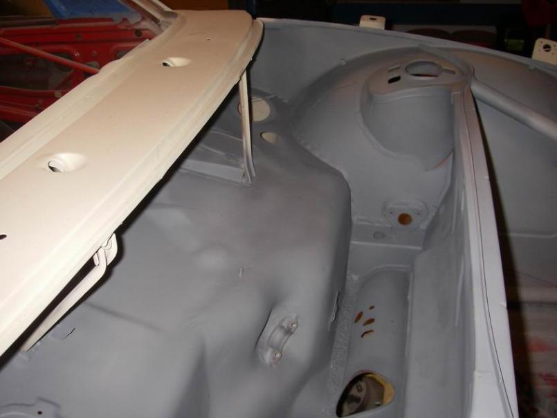
|
|
|
|
| Jeff Hail |
Dec 27 2009, 03:39 AM
Post
#425
|
|
Senior Member Group: Members Posts: 1,141 Joined: 3-May 07 From: LA/ CA Member No.: 7,712 |
The windshield molding clip hole's are all welded up. No need for these any longer. I will use a rubber reveal molding. Pilot holes are all welded up and epoxy primed.
Attached thumbnail(s) 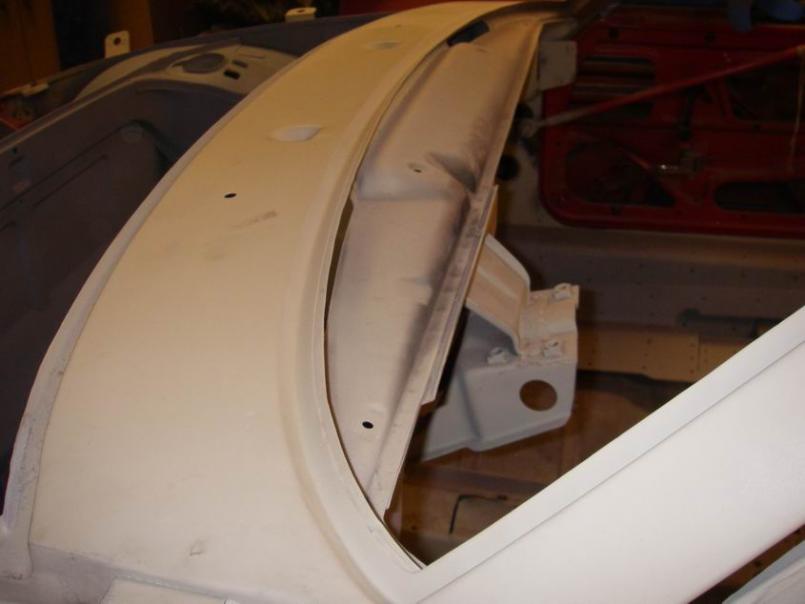 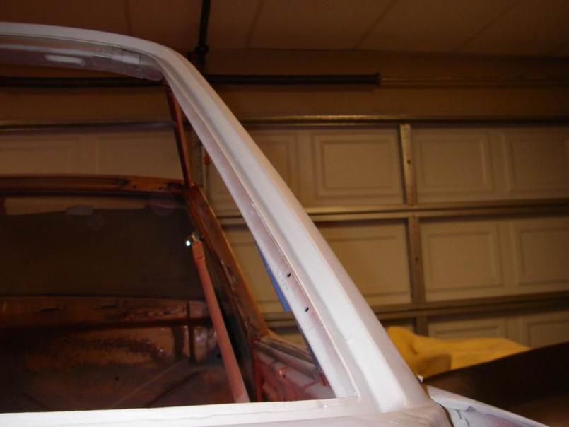
|
|
|
|
| Smitty911 |
Dec 27 2009, 01:14 PM
Post
#426
|
|
Member Group: Members Posts: 294 Joined: 19-March 08 From: La Mirada, Ca Member No.: 8,830 Region Association: Southern California |
WOW, I just sat here and read your entire post.
Amazing commitment to the cause. My '74 2.0 has the same issues as yours on the Driver and Passenger cowl area. I was wondering what was underneith there and how to repair/replace it. Thanks for posting the pictures as you go. Way more skills than I have, that's for sure. Looks like I need a Body Shop. Currently no welder or skills. |
|
|
|
| Rand |
Dec 27 2009, 02:14 PM
Post
#427
|
|
Cross Member Group: Members Posts: 7,415 Joined: 8-February 05 From: OR Member No.: 3,573 Region Association: None |
QUOTE(Jeff Hail @ Nov 26 2009, 12:12 AM)  Front tube structure fully welded in and spot primed. (A Thank you plug to Mr. Foley for the pipe work) What does this do? Sorry if a dumb question. But seriously, I don't get it. Why add weight there? And for what purpose? Seems superfluous. Where's Aaron? He's been doing this to bike frames. (IMG:style_emoticons/default/chair.gif) I love this thread!!! Nice work Jeff. Keep it alive. Attached image(s) 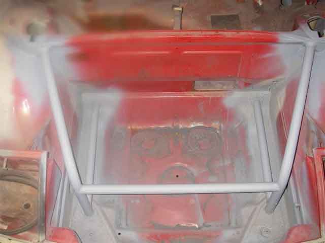
|
|
|
|
| Jeff Hail |
Dec 27 2009, 03:45 PM
Post
#428
|
|
Senior Member Group: Members Posts: 1,141 Joined: 3-May 07 From: LA/ CA Member No.: 7,712 |
Picture the bigger picture. Front substructure ties the towers into the lower control arm mounts and crossmember mounts, kind of faux triangulation Front substructure tied to front loop from the towers through the dash and rearward into a main loop. Central cage tied to rear longs/ towers. The 6 motor mount plates will be tied into the lower loop tubes at the lower firewall.
Ok the real reason is so I can ram shit out of the way that doesnt belong in front of me and keep driving:) Ever notice a 914 in hard cornering? You know when the hood corner lifts up? I HATE RADICAL BODY FLEX because it defeats the purpose of suspension. Thats an easy example to picture. A properly set up car should be fun and easy to drive also providing feedback. Good suspension will only be a compromise if the chassis that supports it is the weak link. Weight? Everything that is non essential is gone. Except one heater tube silencer which I still dont know why I put that back in? Now its an oil line guide device. |
|
|
|
| Rand |
Dec 27 2009, 03:56 PM
Post
#429
|
|
Cross Member Group: Members Posts: 7,415 Joined: 8-February 05 From: OR Member No.: 3,573 Region Association: None |
QUOTE(Jeff Hail @ Dec 27 2009, 01:45 PM) Ok the real reason is so I can ram shit out of the way that doesnt belong in front of me and keep driving:) (IMG:style_emoticons/default/laugh.gif) I love your tude. Forgive me, I'm still clueless thinking that anything forward of the suspension is pointless. What are you bracing to up front? |
|
|
|
| Jeff Hail |
Dec 27 2009, 04:41 PM
Post
#430
|
|
Senior Member Group: Members Posts: 1,141 Joined: 3-May 07 From: LA/ CA Member No.: 7,712 |
Dual purpose: Support a fuel tank and stiffen the lower control arm front pivot points. The front pivots do not take much of a side load at all but a simple floor jack test proved the floor just behind the nose panel does rise and fall with body twist.
Porsche knew this when they added a crossmember between the front pivots just behind the nose on the factory racers. Does it really do anything? It simply links the two sides together. |
|
|
|
| Rand |
Dec 27 2009, 05:26 PM
Post
#431
|
|
Cross Member Group: Members Posts: 7,415 Joined: 8-February 05 From: OR Member No.: 3,573 Region Association: None |
QUOTE(Jeff Hail @ Dec 27 2009, 02:41 PM) Porsche knew this when they added a crossmember between the front pivots just behind the nose on the factory racers. Does it really do anything? It simply links the two sides together. Porsche thought they knew something with the GT stiffening kits too. Turns out they made some mistakes. I guess I'm just overly anal when it comes to adding anything superfluous. (IMG:style_emoticons/default/smile.gif) |
|
|
|
| Jeff Hail |
Dec 28 2009, 10:23 AM
Post
#432
|
|
Senior Member Group: Members Posts: 1,141 Joined: 3-May 07 From: LA/ CA Member No.: 7,712 |
Have to agree with you on the GT stiffening kits.
Personally I think when they cut the opening for the oil cooler the front floor was weakened between the pivots. With or without I think linking the two points does make that area more rigid keeping the control arms as parallel as can be with a minimal modification. Not eliminating flex but minimizing at best undesirable toe changes during loading. Look at all those old original stock lower control arm bushings at the front pivot. Have you ever seen any that arent oddly deformed no matter a 914 or a 911? Normal wear for a rubber bushing with age yes but the front bushings do not take much of a load as much as just locating the control arm. Taken to the extreme of racing both 914's and 911's have been known to have contact (rubbing)between the torsion bar and inside of the control arm tube. I have seen this many times on cars that have no structural misalignment at the control points or damaged arms. The rub marks are always at the crossmember end. Torsion bar is fixed at the front of the control arm. What gives? |
|
|
|
| brp986s |
Dec 28 2009, 01:12 PM
Post
#433
|
|
Member Group: Members Posts: 434 Joined: 27-September 07 From: los angeles Member No.: 8,167 |
"The rub marks are always at the crossmember end. Torsion bar is fixed at the front of the control arm. What gives?"
At the crossmember end, the ID of the a-arm bushing is rotating with suspension travel, but the OD of the bushing is stationary. Consequently, over time gravity and twisting will cause the torsion bar to burrow through the bushing until it contacts the crossmember. The further forward along the torsion bar you go there is less rotation of the torsion bar so there is less wear at the forward bushing. But, here is something to consider. Continued loading and unloading forces around the front a-arm mount fatigues the sheet metal leading to cracks. It happened on my car and others I've seen. At its extreme the car would fall onto the tire, just like a broken torsion bar, although I've never heard of this happening. If you joined the front mounts with a hoop you could alleviate stress on the chassis. When you had the brace removed for rust repair I thought maybe you had this in mind. |
|
|
|
| Jeff Hail |
Jan 24 2010, 04:17 AM
Post
#434
|
|
Senior Member Group: Members Posts: 1,141 Joined: 3-May 07 From: LA/ CA Member No.: 7,712 |
Delete
|
|
|
|
| Jeff Hail |
Jan 24 2010, 04:24 AM
Post
#435
|
|
Senior Member Group: Members Posts: 1,141 Joined: 3-May 07 From: LA/ CA Member No.: 7,712 |
Just before I left I have was assessing the left inner long. Removal of the motor mount and console. I figured time for more measurements before committing to more alchemy. The next step is repair of the left long in preparation of the installation of the highly awarded Racer Chris raised rear pickups.
I measured from the rear console outer hole to the front suspension crossmember rear mounting points. Triangulate both sides. I have never been a fan of the factory measurements. They provide a good detail of the body dimensions but the suspension control points have always been lacking with published data. Attached thumbnail(s) 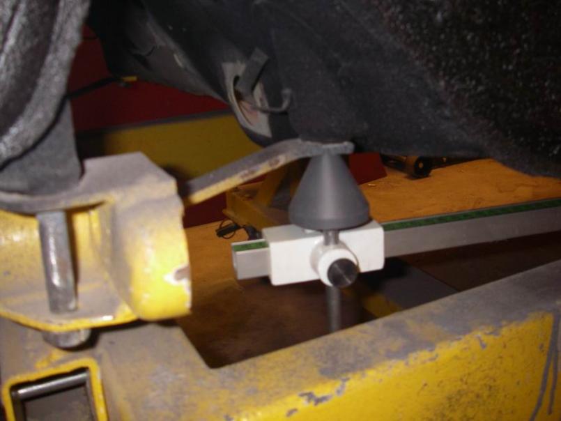 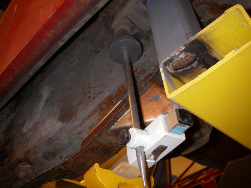 Attached image(s) 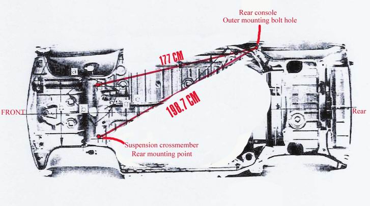
|
|
|
|
| ChrisFoley |
Jan 24 2010, 07:04 AM
Post
#436
|
|
I am Tangerine Racing Group: Members Posts: 8,031 Joined: 29-January 03 From: Bolton, CT Member No.: 209 Region Association: None |
I know of a healer (nagual) in Bali who also teaches a series of invigorating movements not unlike Tai Chi, called Dragons Tears and Tapping. He goes by the name Lujan Matus and is very effective at helping people get to the inner source of their troubles, either physical or emotional. He is the living embodiment of the ancient knowledge written about by Carlos Castaneda.
BTW, the reason the torsion bars rub the inside of the control arm is because the bar is supported by the torsion bar adjuster which acts s a lever since its point of contact is 2 inches away from torsion bar centerline. This lifts the rear end of the bar as the vehicle weight is transferred through the a-arm. |
|
|
|
| ChrisFoley |
Jan 24 2010, 07:15 AM
Post
#437
|
|
I am Tangerine Racing Group: Members Posts: 8,031 Joined: 29-January 03 From: Bolton, CT Member No.: 209 Region Association: None |
QUOTE(brp986s @ Dec 28 2009, 02:12 PM) At the crossmember end, the ID of the a-arm bushing is rotating with suspension travel, but the OD of the bushing is stationary. Consequently, over time gravity and twisting will cause the torsion bar to burrow through the bushing until it contacts the crossmember. The torsion bar is nowhere near the bushing, which is outside the control arm tube. QUOTE The further forward along the torsion bar you go there is less rotation of the torsion bar so there is less wear at the forward bushing. Both bushings are affected equally by the a-arm rotating as the suspension moves up and down. They have no contact with the torsion bar but they do lose plasticity as the rubber ages. As the rubber hardens over time it may transmit greater forces into the carriers instead of absorbing them. QUOTE Continued loading and unloading forces around the front a-arm mount fatigues the sheet metal leading to cracks. It happened on my car and others I've seen. At its extreme the car would fall onto the tire, just like a broken torsion bar, although I've never heard of this happening. If you joined the front mounts with a hoop you could alleviate stress on the chassis. When you had the brace removed for rust repair I thought maybe you had this in mind. It is the aging rubber which causes the forces to be transmitted into the sheet metal. There is hardly any force around the front mount from the torsion bar. If the sheet metal actually breaks it will not cause the suspension to drop like a broken torsion bar since the lifting forces aren't transmitted through the front mount. The only thing I have ever seen in that area is the mounting reinforcement broken free, due to inadequate spot welds from the factory. |
|
|
|
| TJB/914 |
Jan 24 2010, 10:13 AM
Post
#438
|
|
Mid-Engn. Group: Members Posts: 4,500 Joined: 24-February 03 From: Plymouth & Petoskey, MI Member No.: 346 Region Association: Upper MidWest |
QUOTE(Jeff Hail @ Jan 24 2010, 02:17 AM) I am on leave. Family issues, woman is upset with me. A spur of the moment short break from the daily grind. What else is new? Currently I am in Nusa Dua. I lost a day somewhere in flight between here and Taipei , strange it is. Ten different languages spoken all around me. Monkeys screaming all night outside my villa window. My cell phone says its California time 1-24-10 2:11 am but it’s really 6:15pm here. Time is an illusion right now. Real strong East Java coffee at the Moka Cafe will cure this I hope? This is so cool. Forget getting outside the box. The box doesn’t exist here. I could live here. My guest (Nurse Carol) is so appreciative to be my travel companion. Asked her to go to Bali with me on a moment’s notice due to other upset woman being stubborn and hard headed. (The Twisted One -Clayton would understand) Someone do something about those monkeys. Wow, Jeff your metal workmanship is off the chart. (IMG:style_emoticons/default/smilie_pokal.gif) Your personal life is too. (IMG:style_emoticons/default/popcorn[1].gif) Advise: Shoot the monkey's with your handgun and send a photo of (Nurse Carol). (IMG:style_emoticons/default/rolleyes.gif) You are an inspiration to all 914er's. (IMG:style_emoticons/default/wub.gif) Tom |
|
|
|
| brp986s |
Jan 24 2010, 11:32 AM
Post
#439
|
|
Member Group: Members Posts: 434 Joined: 27-September 07 From: los angeles Member No.: 8,167 |
[quote] Continued loading and unloading forces around the front a-arm mount fatigues the sheet metal leading to cracks. [/quote]
It is the aging rubber which causes the forces to be transmitted into the sheet metal. There is hardly any force around the front mount from the torsion bar. If the sheet metal actually breaks it will not cause the suspension to drop like a broken torsion bar since the lifting forces aren't transmitted through the front mount. The only thing I have ever seen in that area is the mounting reinforcement broken free, due to inadequate spot welds from the factory. [/quote] Not true. And the bushing is irrelevant. If 500 ft-lbs of clockwise torque is required at th rear of the t-bar to suspend the car, there better be 500 ft-lbs counterclockwise torque at the front, or that sucker is gonna fall. The chassis sees 100% of that torque. Dynamically, the forces can vary considerably depending on spring rate and etc, and those forces do in fact fact fatigue the chassis - I've seen it. |
|
|
|
| ChrisFoley |
Jan 24 2010, 04:13 PM
Post
#440
|
|
I am Tangerine Racing Group: Members Posts: 8,031 Joined: 29-January 03 From: Bolton, CT Member No.: 209 Region Association: None |
QUOTE(brp986s @ Jan 24 2010, 12:32 PM) The chassis sees 100% of that torque. Yup, almost all of it through the rear support crossbar - at the adjuster. Nearly 0% is applied through the front mounts, except for the resistance of the bushings! If your car is any different you have something else wrong. The end of the t-bar connected to the a-arm is at the front. The end of the t-bar connected to the chassis is at the rear. QED |
|
|
|
|
2 User(s) are reading this topic (2 Guests and 0 Anonymous Users)
0 Members:

|
Lo-Fi Version | Time is now: 18th July 2026 - 12:07 AM |
Invision Power Board
v9.1.4 © 2026 IPS, Inc.