|
|
|
Porsche, and the Porsche crest are registered trademarks of Dr. Ing. h.c. F. Porsche AG.
This site is not affiliated with Porsche in any way. Its only purpose is to provide an online forum for car enthusiasts. All other trademarks are property of their respective owners. |
|
|

  |

| Gint |
 Oct 21 2007, 05:22 PM Oct 21 2007, 05:22 PM
Post
#61
|
|
Mike Ginter  Group: Admin Posts: 16,108 Joined: 26-December 02 From: Denver CO. Member No.: 20 Region Association: Rocky Mountains |
(IMG:style_emoticons/default/agree.gif) Nice work. I wish I had the talent to do all of that work myself.
|
   |

 
|
| Jeff Hail |
Oct 21 2007, 06:37 PM
Post
#62
|
|
Senior Member Group: Members Posts: 1,141 Joined: 3-May 07 From: LA/ CA Member No.: 7,712 |
A valid PM was sent to me by Wes in reference to metal fatigue. On my previous post I may not have been clear but I will try to explain by example.
I referred to high stress/ high flex areas and double walls. Where the inner long come's together with the rear frame rail it was double walled by the factory highlited in red. If I were to just weld the inner long to the rear frame rail without the double wall it would be a very flexible joint and eventually fail. This would be compounded by suspension movement and engine weight and torque. This area is where the rear center section of the tub (torque box) ties into the rear structure of the vehicle. This area needs to be as strong or stronger than the factory designed it to be. Everytime the suspension compresses this area is subjected to load. Everytime the vehicle is launched it is subject to load. These parts are made of 18 guage sheetmetal which is not very thick. The area where the inner long ties into the rear frame rail is subject to high flex. The load of the rear section of the unibody is partially transfered to the long connection. The long is a straight box and then kicks up into what is known as the Hell Hole. If rust of damage occurs at this area it will or has become fatigued with use. In a worse case scenario the car will sag. First because the supporting metal in this area has disappeared and second what metal left is supporting the weight of the car and suspension loads. It give's way. This is usually observed by a tight door gap in a very bad case of rust. The example shown with the "paper template" would reflect the double wall at this connection. The purpose of the double wall is to spread the load at the joint into a larger area. This will reduce the load carried by the long/ rail connection at the seam/ weld area only. Because the rear rail is kicked up it acts as a lever pushing up each time the suspension compress's. The second wall controls the allowed flex in this area reducing fatigue that the long/ rail joint is subjected to. An easy understanding would be a paper clip. A large paper clip is about 18 guage or so. If you straighten it out and then bend it back and forth it will break in two. Now take 10 paper clips and do the same thing all grouped in a bundle. It will be more difficult to bend 10 bundled and the bend area is now radiused into a larger area. If the paperclip is allowed to flex in a small area versus a larger area it will take less cycles to break. The same principle with sheetmetal applies except the long is comprised of a 3 sided box speading the load into a larger area into the wheelhouse and firewall connections. Hope this helps Attached image(s) 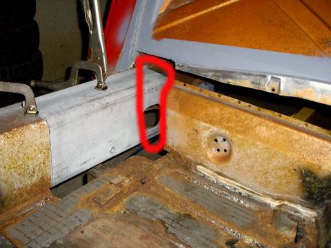 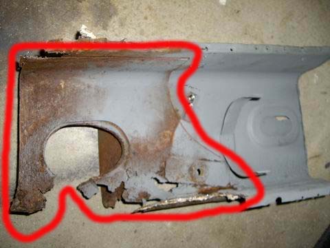 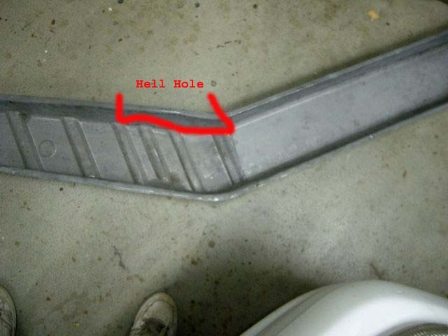 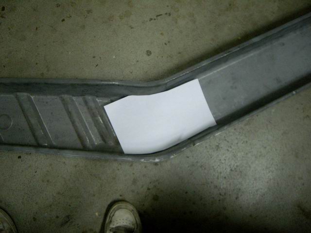
|
|
|
|
| Wes V |
Oct 21 2007, 07:46 PM
Post
#63
|
|
Member Group: Members Posts: 482 Joined: 11-October 07 From: Los angeles Member No.: 8,211 |
QUOTE(Jeff Hail @ Oct 21 2007, 05:37 PM)  A valid PM was sent to me by Wes in reference to metal fatigue. On my previous post I may not have been clear but I will try to explain by example. Thanks for not taking the PM the wrong way! But that still doesn't answer if it's possible to swing by! Wes Vann |
|
|
|
| Jeff Hail |
Oct 21 2007, 07:47 PM
Post
#64
|
|
Senior Member Group: Members Posts: 1,141 Joined: 3-May 07 From: LA/ CA Member No.: 7,712 |
Another example of double walled panels.
The right wheelhouse assembly. This is an AA part. Notice where the double walls are? Extra layer added all thoughout the rail area which supports the the motor mounts and suspension console also. Sorry George, pretty rough part if you ask me. If the guys used oil or wax in the dies those hidious wrinkles at the battery tray area would not be half as bad! Attached image(s) 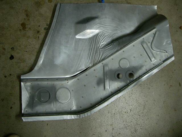 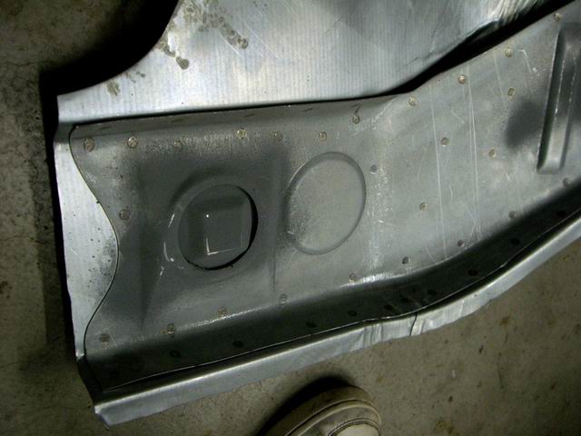
|
|
|
|
| Jeff Hail |
Oct 26 2007, 11:50 PM
Post
#65
|
|
Senior Member Group: Members Posts: 1,141 Joined: 3-May 07 From: LA/ CA Member No.: 7,712 |
type11969 has a few questions regarding Roloc disc's
3M is not the only one who makes the threaded plastic hub abrasive discs that fits the standard Roloc arbors/adaptors. I use a few off brands as well. The ones I use more of are for clutch and brake disc conditioning. Same fine grits available as 3M for 1/5 the price. I find them in bags of 100 for about $20.00 One of my local suppliers retired so I now have to order them from an internet supplier ( Autobody Tool Mart) which is a great supplier of body needs. You can find them at www.autobodytoolmart.com or 1-800-382-1200 The Rolocs disc's and arbors are pictured below. The arbor adaptors are the same for small sanding disc's so everything is a quick change universal fit. These are the standard of the autobody industry. Very convenient and long lasting. The part # for the (3M) arbor/ backing pad's are: 1 inch- 05538 2 inch- 05539 3 inch- 05540 These are 1/4 inch shanks. I included a picture of the die grinders they fit. The disc's are available in both sanding discs and conditioning disc's. Sanding discs are available in 24,36,50 grits and are round sand paper disc's. (The Green Corp's- 3M) Conditioning disc's come in fine , medium and course. These are the one's I prefer as they last long and do not thin metal. They smooth and clean the surface. They look like old dirty panty hose spun with resin. The fine grit doesn't leave sand scratches and requires almost no finish work. The big nasty looking black disc's on the right are 3M Clean and Strip disc's. Two kinds are available. Roloc standard and the big ones as pictured. These take a different arbor which is 1/4 inch that fits any die or angle grinder. The same arbor for these big disc's would be used on cut-off wheels or weld grinding disc's. These are for aggressive coating removal. If you are stripping large area's I would use Aircraft Stripper. Work smart not hard. If you are stripping thin gauge exterior body panels (fend's , door's qtr's, hood's etc) you do not want to apply heat with rotating abrasives. A lo speed DA is ok but still a lot of work. Heat warp's. Use stripper. If you are stripping longs, trunks and other area's that may have thicker metal and are not normally visible on the exterior then alternative abrasives such as Clean & Strip disc's are fast to get down to bare metal. Attached image(s) 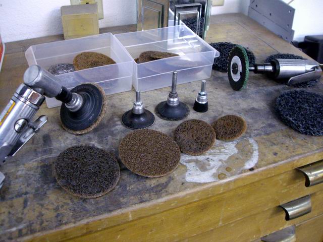 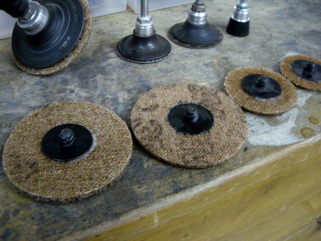 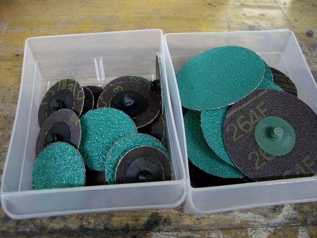
|
|
|
|
| type11969 |
Oct 28 2007, 08:22 AM
Post
#66
|
|
Senior Member Group: Members Posts: 1,231 Joined: 2-December 03 From: Collingswood, NJ Member No.: 1,410 Region Association: North East States |
Thanks Jeff!
|
|
|
|
| Jeff Hail |
Nov 3 2007, 07:45 PM
Post
#67
|
|
Senior Member Group: Members Posts: 1,141 Joined: 3-May 07 From: LA/ CA Member No.: 7,712 |
Didnt get anything done for two weeks. Fire's, house stuff and other distractions took over.
Had a nice solid 4 hours to play today. Cut and trimmed the remainder of the old panels, flanges and junk out. Attached image(s) 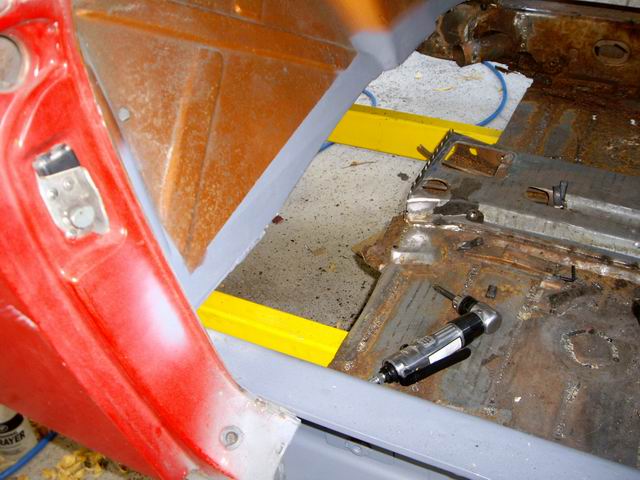 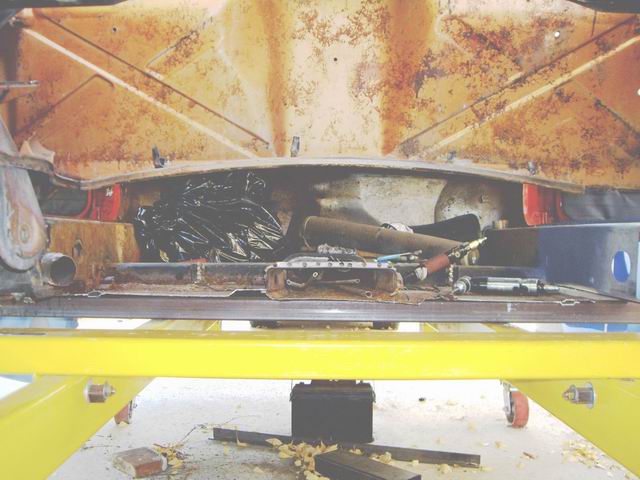 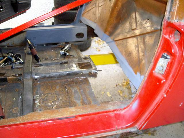
|
|
|
|
| Jeff Hail |
Nov 3 2007, 07:47 PM
Post
#68
|
|
Senior Member Group: Members Posts: 1,141 Joined: 3-May 07 From: LA/ CA Member No.: 7,712 |
Prepped the flanges and seams for the inner and outer firewalls.
Attached image(s) 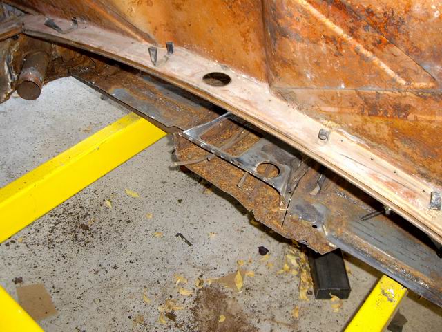 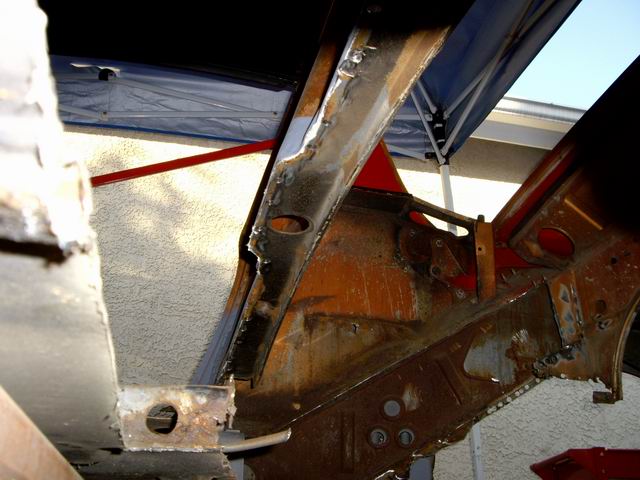
|
|
|
|
| Jeff Hail |
Nov 3 2007, 07:50 PM
Post
#69
|
|
Senior Member Group: Members Posts: 1,141 Joined: 3-May 07 From: LA/ CA Member No.: 7,712 |
Passenger side of the tunnel was just surface rust and came right off with a conditioning pad. Good solid clean metal.
Drivers side very rear of the tunnel has some corrosion that I will need to replace a small section of the last 2-3 inches at floor flange. It's only metal I tell you! Attached image(s) 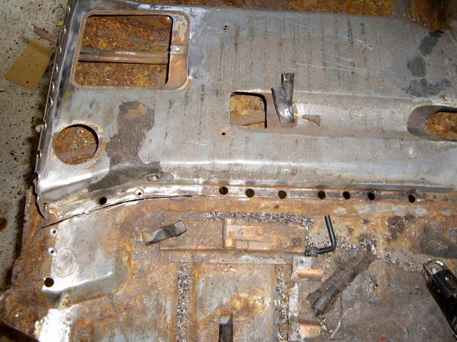 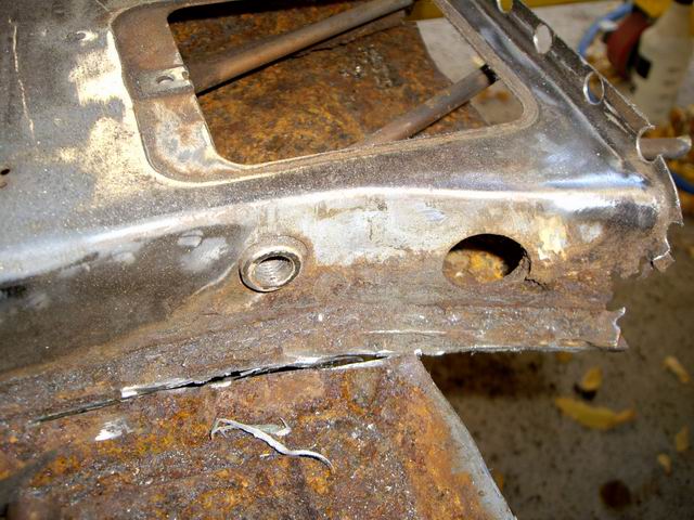
|
|
|
|
| Rand |
Nov 3 2007, 07:58 PM
Post
#70
|
|
Cross Member Group: Members Posts: 7,415 Joined: 8-February 05 From: OR Member No.: 3,573 Region Association: None |
Just wanted to give you a virtual high five here Jeff. This is good stuff. Your thread is destined to be a classic that will help a lot of people. Thanks for digging in deep and sharing the progress with us.
(IMG:style_emoticons/default/smilie_pokal.gif) |
|
|
|
| Jeff Hail |
Nov 3 2007, 08:06 PM
Post
#71
|
|
Senior Member Group: Members Posts: 1,141 Joined: 3-May 07 From: LA/ CA Member No.: 7,712 |
Mocked up the inner and outer firewalls to see how everything fits. No welds just loose.
The outer is a NOS piece and the two lower inners are AA. The AA parts fit pretty damn good. All the locating holes and boss's line right up with the original piece. (George I am impressed) Before I weld these in I will repair the tunnel. I also need to modify the outer firewall because my car is a 75 and the NOS part is for an early car. I will resize the shifter bushing reinforcement to match the later bushings. I will also need to repair the tunnel lines. I had to cut them to get the PO's previous horrors out of the way. McMaster-Carr has the correct size tubing available. I have a few improvements in store from the factory design anyway. The factory E brake handle, location, tubes and elbow's are going away. I have a 1995 993 E Brake assembly that will go between the seats. Attached image(s) 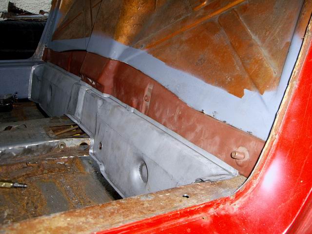 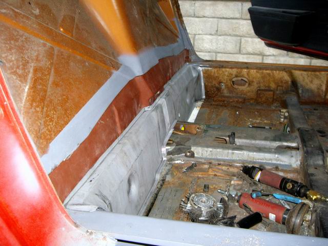 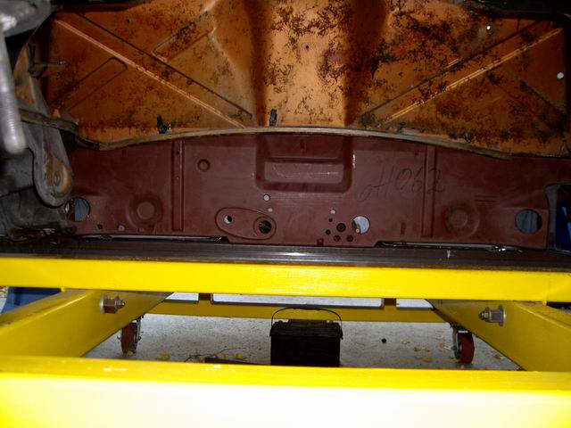
|
|
|
|
| Jeff Hail |
Nov 3 2007, 08:08 PM
Post
#72
|
|
Senior Member Group: Members Posts: 1,141 Joined: 3-May 07 From: LA/ CA Member No.: 7,712 |
Kind of looks like a 914 again!
Still lots to do. Stay tuned for the next episode of "Fun with Clecos" Attached image(s) 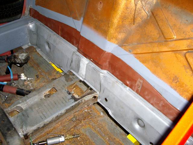 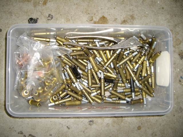
|
|
|
|
| Jeff Hail |
Nov 3 2007, 08:26 PM
Post
#73
|
|
Senior Member Group: Members Posts: 1,141 Joined: 3-May 07 From: LA/ CA Member No.: 7,712 |
One last thing for the day. It is possible to get the J-Tubes out without opening up the longs. My passenger side is open and the driver side is still closed for now. They have 2-4 spot welds holding the bracket. It can be wrangled out.
Get them back in with the longs closed up? Optimisticly I think it can be done. If the silencer pulls off at the front tube is another story. |
|
|
|
| Jeff Hail |
Nov 3 2007, 09:01 PM
Post
#74
|
|
Senior Member Group: Members Posts: 1,141 Joined: 3-May 07 From: LA/ CA Member No.: 7,712 |
QUOTE(Rand @ Nov 3 2007, 06:58 PM) Just wanted to give you a virtual high five here Jeff. This is good stuff. Your thread is destined to be a classic that will help a lot of people. Thanks for digging in deep and sharing the progress with us. (IMG:style_emoticons/default/smilie_pokal.gif) To quote my good friend Mac Tilton "knowledge should be shared...unless of course it is a competing race team then throw tarps over everything". |
|
|
|
| Jeff Hail |
Nov 3 2007, 09:12 PM
Post
#75
|
|
Senior Member Group: Members Posts: 1,141 Joined: 3-May 07 From: LA/ CA Member No.: 7,712 |
Anyone with an early car know what these holes are for? The holes line up on the inner fire wall and inside the shift rod housing on the outer firewall.
I checked all my disassembly photo's and do not see it on the late body. Just wondering what they are for? Attached image(s) 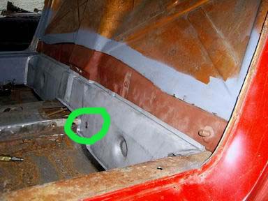 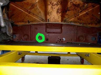
|
|
|
|
| 1970 Neun vierzehn |
Nov 3 2007, 11:58 PM
Post
#76
|
|
Advanced Member Group: Members Posts: 3,199 Joined: 16-March 06 From: cincinnati, ohio Member No.: 5,727 |
QUOTE(Jeff Hail @ Nov 3 2007, 07:12 PM) Anyone with an early car know what these holes are for? The holes line up on the inner fire wall and inside the shift rod housing on the outer firewall. I checked all my disassembly photo's and do not see it on the late body. Just wondering what they are for? Jeff, First, let me heartily applaud your work. The scope, quality, care, attention to detail, and the sheer magnitude of the project are all evident in your (also quality) photos. I salute you. With regard to the extra hole, in what the Porsche parts book refers to as "back wall, lower part", there is a part (and number) assigned to the /6 (1970 only) that could possibly be what you are installing, which was originally intended for use in a /6. I can't speak for the differences between the /4 and /6 down in the rear bulkhead/backwall where you are working. Sounds like it could be transmission related. The part # is 914.501.007.10 Paul |
|
|
|
| sixnotfour |
Nov 4 2007, 10:40 AM
Post
#77
|
|
914 Wizard Group: Members Posts: 11,274 Joined: 12-September 04 Member No.: 2,744 Region Association: NineFourteenerVille |
Yes, that hole is for a pivot ball , But for 4 cylinder only. The six uses a simple two bolt type u-joint .
Here is the six wall peice , It has the motor mount welded to it. (note: the black piece is the part that bolts to engine.) Keep up the great work. Attached image(s) 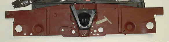
|
|
|
|
| Wes V |
Nov 4 2007, 12:11 PM
Post
#78
|
|
Member Group: Members Posts: 482 Joined: 11-October 07 From: Los angeles Member No.: 8,211 |
For those that may not know;
Clecos are clamps that are used as temporary pop rivets during the fabrication and fitting of parts. If you look at the photo Jeff posted showing the plastic box full of Clecos, you will see what looks like a set of plyers. That's the tool that is used to install and remove the cleco. Wes |
|
|
|
| davep |
Nov 4 2007, 01:32 PM
Post
#79
|
|
914 Historian Group: Benefactors Posts: 5,363 Joined: 13-October 03 From: Burford, ON, N0E 1A0 Member No.: 1,244 Region Association: Canada |
Jeff, can you take some good photos of that panel before you install it, and post them in the parts vault please.
http://www.914world.com/bbs2/index.php?act...amp;s=&f=46 |
|
|
|
| Jeff Hail |
Nov 4 2007, 07:41 PM
Post
#80
|
|
Senior Member Group: Members Posts: 1,141 Joined: 3-May 07 From: LA/ CA Member No.: 7,712 |
Stuff that is easier to do now than later.
I am using an early firewall (PN# 914-501-119-10) which is for a 914/4 thru 1971 to be put on the 1975 body. The NOS firewall does not come with a speedo cable spigot tube. The early firewall has some differences. I will update and modify according to my build. The Speedo Cable Spigot Tube Lets build one.......... The old section versus the replacement. Attached image(s) 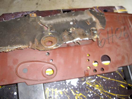 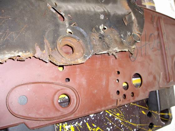 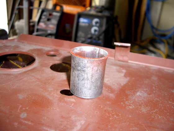 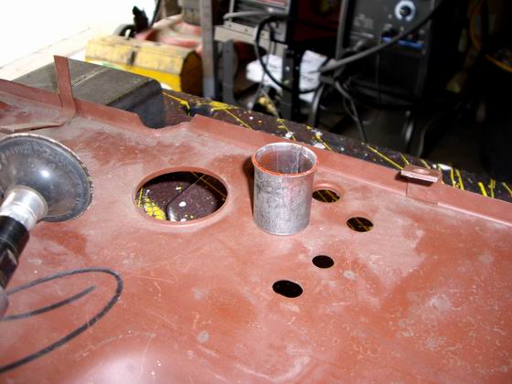
|
|
|
|
|
1 User(s) are reading this topic (1 Guests and 0 Anonymous Users)
0 Members:

|
Lo-Fi Version | Time is now: 26th June 2026 - 07:35 PM |
Invision Power Board
v9.1.4 © 2026 IPS, Inc.