|
|

|
Porsche, and the Porsche crest are registered trademarks of Dr. Ing. h.c. F. Porsche AG.
This site is not affiliated with Porsche in any way. Its only purpose is to provide an online forum for car enthusiasts. All other trademarks are property of their respective owners. |
|
|
  |
| Richard Casto |
 Jul 7 2008, 01:02 PM Jul 7 2008, 01:02 PM
Post
#61
|
|
Blue Sky Motorsports, LLC    Group: Members Posts: 1,465 Joined: 2-August 05 From: Durham, NC Member No.: 4,523 Region Association: South East States |
Thats it for today.
I am taking off next week and hope to get the passenger longitudinal back together. I have yet to fabricate the section directly behind the jack receiver tube. I have the restoration design outer longitudinal as well as the receiver tube and pyramid. I also am shopping for a seat and since I can't test fit the seat in the car, I am driving to a place that has the seat I am looking for and am going to fabricate the wooden replica of the driver floor area. Mostly the width between the longitudinal and the center tunnel as well as the cross member. This will allow me to lay the box on the floor, place the seat in the box and then sit in the seat. |
| Cupomeat |
 Jul 8 2008, 10:41 AM Jul 8 2008, 10:41 AM
Post
#62
|
|
missing my NY 914 in VA    Group: Members Posts: 1,338 Joined: 26-November 07 From: Oakton VA Member No.: 8,376 Region Association: MidAtlantic Region |
This is great stuff, thanks!
It gives me inspiration to start digging into the small holes that have appeared on my lower inner trailing arm mount. Heck, what is the worst I can find, LOL? Excellent work that impresses and inspires me. (IMG:style_emoticons/default/pray.gif) eric |
| Richard Casto |
 Jul 22 2008, 09:45 PM Jul 22 2008, 09:45 PM
Post
#63
|
|
Blue Sky Motorsports, LLC    Group: Members Posts: 1,465 Joined: 2-August 05 From: Durham, NC Member No.: 4,523 Region Association: South East States |
Made some progress last week. I had taken the week off for vacation and worked about four hours a day over five days. I made more progress than these pictures show...
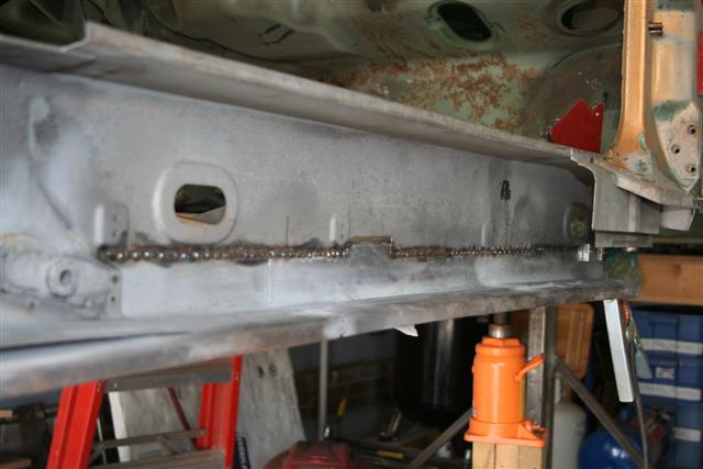 Here the part I fabricated is welded in. When butt welding thin sheet metal, you have to do short welds and space them apart and let it cool. Rinse and repeat until you are done. You should alternate back and forth between front and back as when the weld cool they will pull the metal toward the weld. That will help cut down on warping. 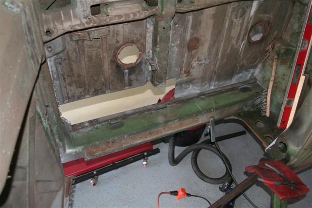 With it welded in place the car is strong enough that I don't need to support it with jacks and can now rotate freely on the rotisserie. This also allows me to put this section level with the floor so I don't have to weld out of position. |
| Richard Casto |
 Jul 22 2008, 09:50 PM Jul 22 2008, 09:50 PM
Post
#64
|
|
Blue Sky Motorsports, LLC    Group: Members Posts: 1,465 Joined: 2-August 05 From: Durham, NC Member No.: 4,523 Region Association: South East States |
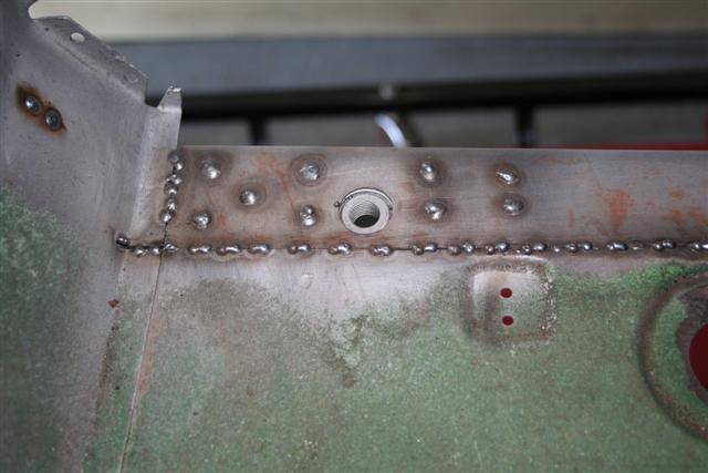 Close up of the rosette "spot welds" near the passenger seat belt anchor. Also you can see the unfinished but welds on the joining seam. Upper left is some welds in a previous butt weld that had some pinholes. 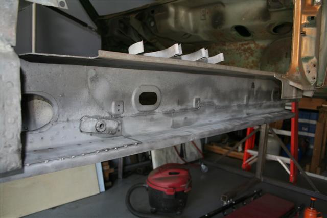 All done. I grinded down the butt weld on the interior all the way to achieve a smooth finish, but on the inside I didn't grind it down flush as there is no need. This will be hidden and I just dressed up the welds. I then lightly media blased the welds to remove all oxidation and then sprayed with Metal Ready. Metal Ready is great stuff. |
| SGB |
 Jul 22 2008, 09:56 PM Jul 22 2008, 09:56 PM
Post
#65
|
|
just visiting     Group: Members Posts: 4,086 Joined: 8-March 03 From: Huntsville, AL Member No.: 404 Region Association: South East States |
"thass purty"
|
| Richard Casto |
 Jul 22 2008, 09:58 PM Jul 22 2008, 09:58 PM
Post
#66
|
|
Blue Sky Motorsports, LLC    Group: Members Posts: 1,465 Joined: 2-August 05 From: Durham, NC Member No.: 4,523 Region Association: South East States |
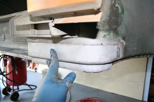 Next I fabricated this piece. As you can see it is part of the front fender well as well as the base for what the front of the outer longitudinal welds onto. I just need to drill holes in the bottom for the rosette welds and then butt weld the top and side. I don't have photos, but I also refurbished the front and rear metal pipes for the heater tube. That is about as far as I got last week. Next steps are... * Fabricate new brackets for the pipes (have template from old) * Weld in floor section * Weld floor to longitudinal * Finish welding in section (skin) behind inner rear suspension console * Clean and wash out interior of box section near rear suspension console * Final Metal Ready treatment * POR 15 hard to reach places * Weld in heater tube brackets and pipes * POR 15 remaining places * Weld in section shown above * Weld in outer longitudinal At that point it will be done other than the area around the jack point and stuff like the sill plate and other surface items. Thats it for now! |
| 3d914 |
 Jul 23 2008, 08:40 PM Jul 23 2008, 08:40 PM
Post
#67
|
|
Senior Member    Group: Members Posts: 1,275 Joined: 24-September 03 From: Benson, AZ Member No.: 1,191 Region Association: Southwest Region |
Richard,
THis is awesome stuff. I have taken on a similar rebuild project, but have begun to cringe at the idea of digging into the Hell Hole! I have a couple of questions . . . 1) Are there any cross-section drawings or photos that show the layers of metal for the rear passenger longs - near where the battery tray leaks? Or do I just have to cut through one layer at a time? 2) You may have mentioned it in a previous posting (and if so point me to the page) - but what type & model of welder are you using (Mig, Tig, Flux)? Thanks & keep up the great job! |
| Richard Casto |
 Jul 24 2008, 08:54 AM Jul 24 2008, 08:54 AM
Post
#68
|
|
Blue Sky Motorsports, LLC    Group: Members Posts: 1,465 Joined: 2-August 05 From: Durham, NC Member No.: 4,523 Region Association: South East States |
Richard, THis is awesome stuff. I have taken on a similar rebuild project, but have begun to cringe at the idea of digging into the Hell Hole! I have a couple of questions . . . 1) Are there any cross-section drawings or photos that show the layers of metal for the rear passenger longs - near where the battery tray leaks? Or do I just have to cut through one layer at a time? 2) You may have mentioned it in a previous posting (and if so point me to the page) - but what type & model of welder are you using (Mig, Tig, Flux)? Thanks & keep up the great job! Hey don't be afraid. It is scary, but you will sleep better at night knowing it is done. (IMG:style_emoticons/default/biggrin.gif) I have felt depressed at times when it was all torn and cut apart, but now that it is going back together I feel much better. (IMG:style_emoticons/default/aktion035.gif) Regarding question #1. Here are two good threads... http://www.914world.com/bbs2/index.php?showtopic=66790 http://www.914world.com/bbs2/index.php?showtopic=66637 The first is AA showing a bunch of repro parts welded together. Look for the post #13 from McMark. He talks about how the repro parts are not 100% accurate in that the section below the battery on the inside is two layers. The inner layer has a corrogated shape (which the repro has as well). Then there is an outer skin that covers this. Both make a "C" shape and it is the outer skin that has the flang that is spot welded to the rest of the car. In the second you can see some nice detail photos taken from where the jack receiver would be back into the inside of the hell hole. You can see the corrogated metal and how the "C" is built and how the corrogated part is not as wide as the rest. I have some similar photos in this thread and on my site, but I think these are a bit better than mine. Regarding #2. I am using a basic 220V Lincoln MIG unit with non-flux .025 wire (using gas). Because this is thin metal welding so a 110V unit would be just fine. I really expensive unit with more flexability on settings would work even better (with regards to setting on the welder), but I think that successfully welding thin sheet metal is 90% technique. Just practice a lot and get used to what setting/technique work well for you. (IMG:style_emoticons/default/welder.gif) Good luck on your car! Richard |
| Richard Casto |
 Nov 11 2008, 03:01 PM Nov 11 2008, 03:01 PM
Post
#69
|
|
Blue Sky Motorsports, LLC    Group: Members Posts: 1,465 Joined: 2-August 05 From: Durham, NC Member No.: 4,523 Region Association: South East States |
It has been quite awhile since I have updated this thread. Here is some progress over the late summer and early fall.
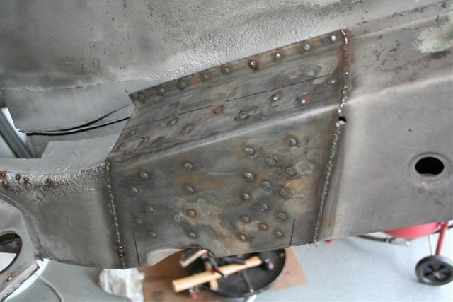 Welded in the replacement skin for the area directly behind the 4-cyl engine mount. Also part of the suspension console covers this. 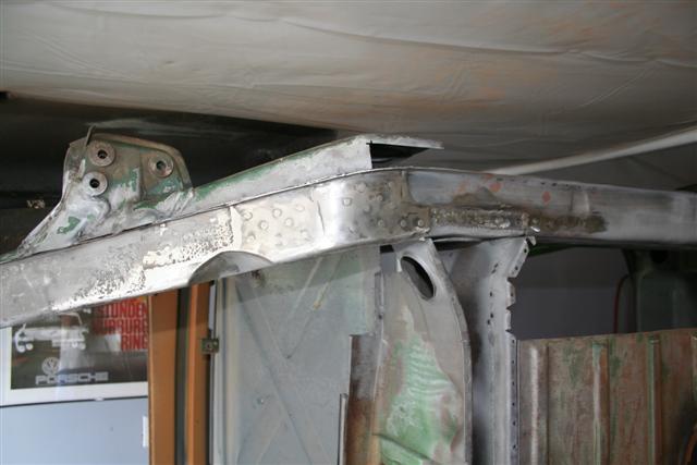 View from below. I will do some final grinding of welds when doing prep for paint. 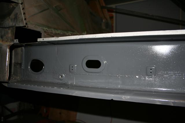 Working toward finishing the passenger longitudinal. Here I have painted the interior with POR-15. 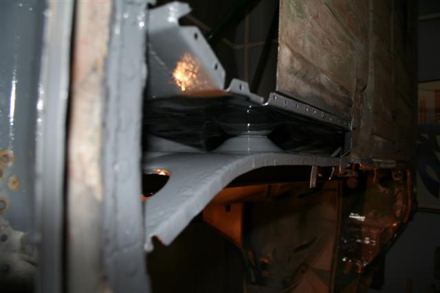 More POR-15, but this is a shot from under the car into the hollow bulkhead behind the seats. 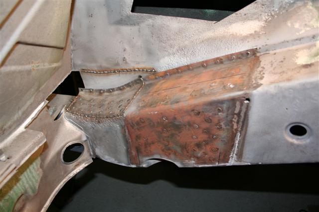 Some flash rust on the part I put on above, but here I have welded in the main "Hell Hole" repair section. |
| Richard Casto |
 Nov 11 2008, 03:11 PM Nov 11 2008, 03:11 PM
Post
#70
|
|
Blue Sky Motorsports, LLC    Group: Members Posts: 1,465 Joined: 2-August 05 From: Durham, NC Member No.: 4,523 Region Association: South East States |
Now we move onto the inner passenger suspension console. This is a part I sourced from Restoration Design awhile back. First I drilled all of my plug weld hold, media blasted the replacement part, treated with Metal Ready, painted the interior non weldable areas with POR-15 and then finally the interior weldable areas with U-POL weldable primer.
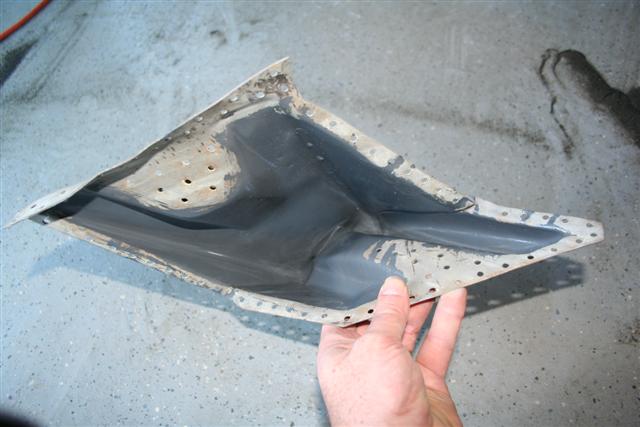 With POR-15. Not I bent the upper flange out so I could get a good tight fit on the bottom. 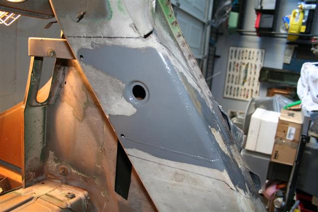 More POR-15 on non-weldable areas. This shot doesn't show the weldable primer that I am about to spray on. 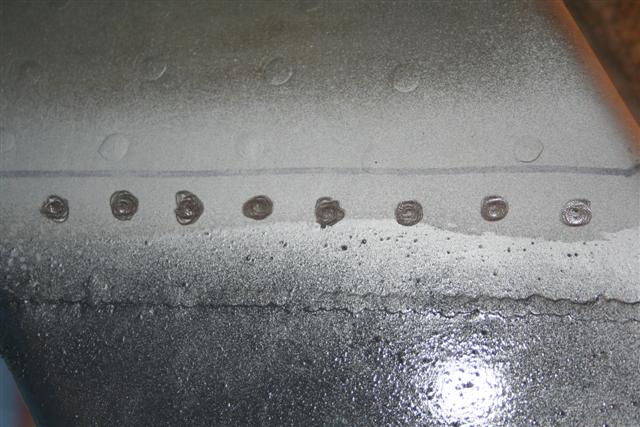 Here is weldable primer, but I don't really like it that much. So I used an air die grinder with a stone and knock off the paint on the spots I will be doing my plug weld. 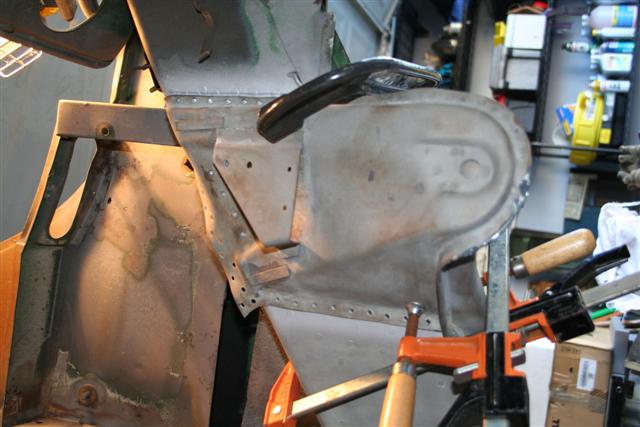 Clamped into place. At this point I measure to make sure it is in the correct location (use the good driver side as a guide), then tack weld one or two places, remeasure to make sure it hasn't moved and then do more plug welds. Again you can see the top flange bent up for the moment. 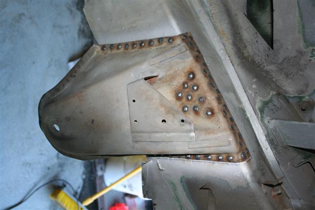 All done except for welding down the plug welds. 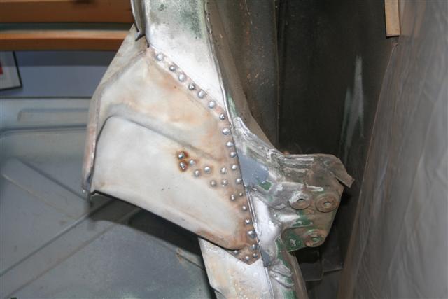 Shot from below. I will eventually need to rebuild the "bridge" that goes between the inner and out consoles. |
| Richard Casto |
 Nov 11 2008, 03:18 PM Nov 11 2008, 03:18 PM
Post
#71
|
|
Blue Sky Motorsports, LLC    Group: Members Posts: 1,465 Joined: 2-August 05 From: Durham, NC Member No.: 4,523 Region Association: South East States |
I generally do the welding stuff on the weekends when I can be noisy. If I work at night, I need something a bit quieter to work on. So I decided to refurbish the front suspension. I sourced a 911 front end that uses OEM Koni style struts. I have about 90% or so of what I need to rebuild much of the front suspension. First task is to disassemble the struts, strip and then powder coat them.
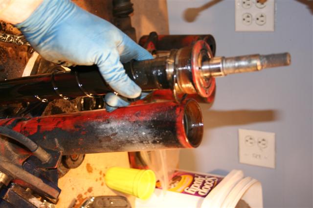 Here is the OEM Koni strut. This is not an insert in the style of the current self contained Koni inserts, but rather this is the shock internals along with the shock oil that had to be drained. I will be putting in newer Koni "yellow" sport inserts into this strut. 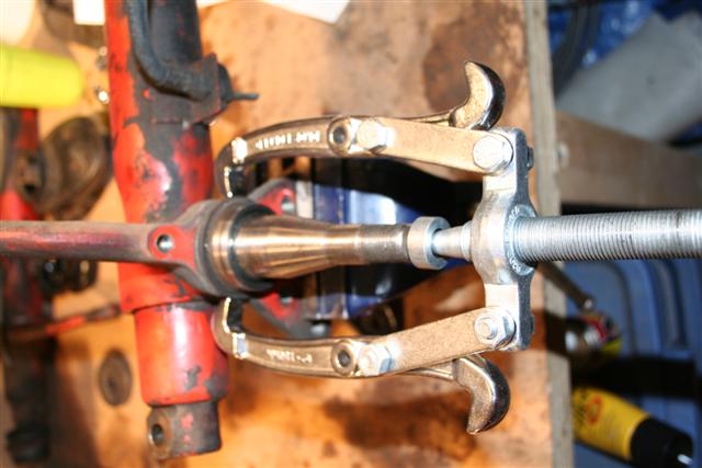 Here is something that I don't think many people do when redoing a strut. I am pulling off this ring that is on the spindle. Why am I doing this?... 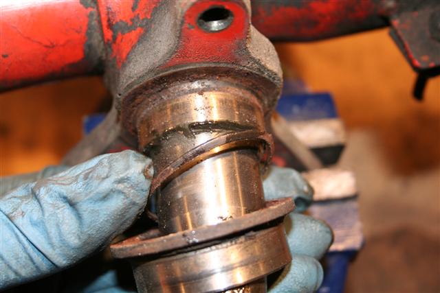 Because there is an O-ring behind it that I want to replace. This O-ring looks to be pretty dead. |
| TravisNeff |
 Nov 11 2008, 03:20 PM Nov 11 2008, 03:20 PM
Post
#72
|
|
914 Guru      Group: Members Posts: 5,082 Joined: 20-March 03 From: Mesa, AZ Member No.: 447 Region Association: Southwest Region 
|
Great attention to detail!
|
| Richard Casto |
 Nov 11 2008, 03:22 PM Nov 11 2008, 03:22 PM
Post
#73
|
|
Blue Sky Motorsports, LLC    Group: Members Posts: 1,465 Joined: 2-August 05 From: Durham, NC Member No.: 4,523 Region Association: South East States |
Great attention to detail! Thanks! I think this car is a keeper so I am trying to do it right. (IMG:style_emoticons/default/smile.gif) |
| Richard Casto |
 Nov 11 2008, 03:34 PM Nov 11 2008, 03:34 PM
Post
#74
|
|
Blue Sky Motorsports, LLC    Group: Members Posts: 1,465 Joined: 2-August 05 From: Durham, NC Member No.: 4,523 Region Association: South East States |
Now comes the fun that I have been looking forward to for a long time. I have had a Caswell powder coating kit and a junk yard oven for over a year, but have not had a chance to try it all out yet. So my first powder coating is with my strut dust covers as well as the special gland nuts that allow you to use a Koni insert in the OEM Koni strut
First I stripped the old paint off with Jasco. Then I washed them with soap and water and solvents to get the grease and oil off. Then I glass bead blasted them. Then I treated them with Metal Ready. I then washed them in water one last time then oven dried them. 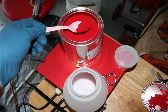 Powder goes into cup. 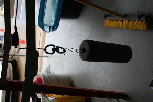 Hang part. Ground it to your corona gun. Make sure you have a swivel so you can rotate part as needed. 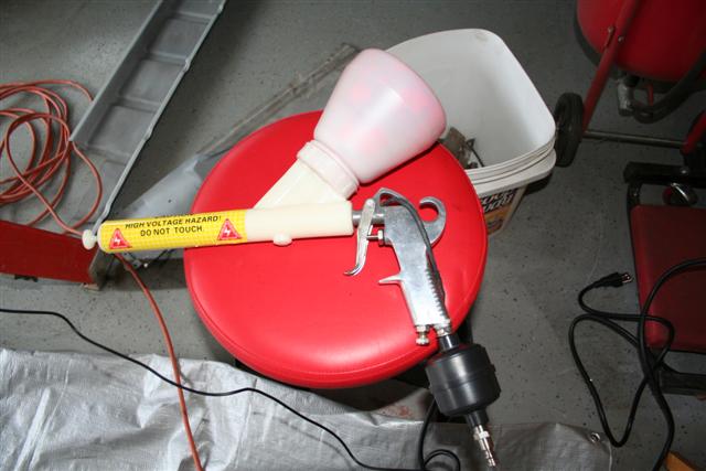 Gun all loaded and ready to go. 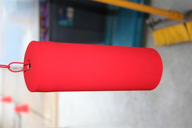 Part is now coated with powder. Sorry no action shots as I couldn't take photos and use the gun at the same time. (IMG:style_emoticons/default/biggrin.gif) Powder can just be wiped or blown off at this point. So you have to be carefull as you... 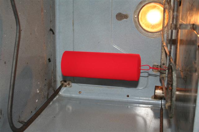 ...transfer into the oven. I drilled holes in the top of the oven to install some loops that I can hang parts from. Oven was pre-heated to about 400 F prior to me putting the part in. 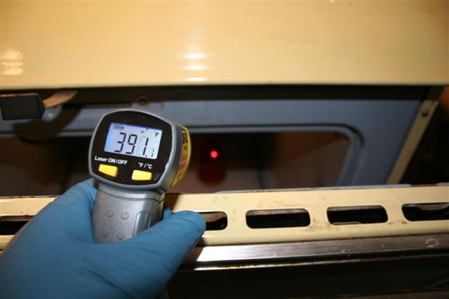 Powder spec says 392 F for 10 minutes. Within just a few minutes that part has warmed up to 390-400 F and the powder will melt. Crack open the oven just a bit and check temp with IR thermo. Once you are sure part is at cure temp, let it bake for 10 minutes. After 10 minutes, turn off oven, crack door a bit and allow it to cool down slowly. 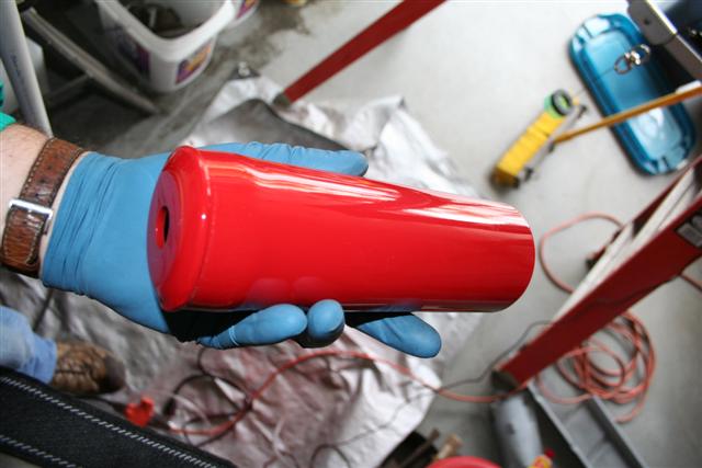 Finished product looks awsome! Especially as this is my very first part! 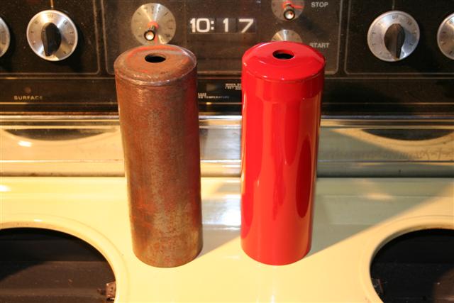 Other cover that has been stripped with Jasco, but prior to media blasting, etc. 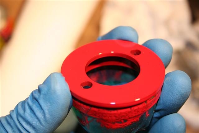 Here is one of the gland nuts. I used high temp green silicone tape to cover the threads. You can see some of the cured paint on the tape, but once you pull the tape off you can see that the threads are untouched by paint. |
| Richard Casto |
 Nov 11 2008, 03:37 PM Nov 11 2008, 03:37 PM
Post
#75
|
|
Blue Sky Motorsports, LLC    Group: Members Posts: 1,465 Joined: 2-August 05 From: Durham, NC Member No.: 4,523 Region Association: South East States |
Ok, that is it for now. I hope to work on powder coating the struts tonight, but that is on the assumption that I don't run into problems getting the holes and mating surfaces taped up and that the strut hangs in the oven correctly.
|
| r_towle |
 Nov 11 2008, 03:39 PM Nov 11 2008, 03:39 PM
Post
#76
|
|
Custom Member                Group: Members Posts: 24,705 Joined: 9-January 03 From: Taxachusetts Member No.: 124 Region Association: North East States 
|
this is awesome and I love the work...great detail.
One question. The high temp tape. where do you get it and what temp can it handle??? Rich |
| Richard Casto |
 Nov 11 2008, 03:45 PM Nov 11 2008, 03:45 PM
Post
#77
|
|
Blue Sky Motorsports, LLC    Group: Members Posts: 1,465 Joined: 2-August 05 From: Durham, NC Member No.: 4,523 Region Association: South East States |
this is awesome and I love the work...great detail. One question. The high temp tape. where do you get it and what temp can it handle??? Rich Rich, I bought my supplies (kit, powder and tape) from Caswell. Here is the link to the tape... http://www.caswellplating.com/powder/powder_tape.html I used the green tape which is rated to 400F. They also have tape rated to 600F. You can also use silicon plugs for things like bolt holes, etc. that you don't want paint in. I didn't buy the silicon plugs and am going to try to use tape for this. I will post here as to how well that works. Richard |
| charliew |
 Jan 5 2009, 09:34 PM Jan 5 2009, 09:34 PM
Post
#78
|
|
Advanced Member     Group: Members Posts: 2,363 Joined: 31-July 07 From: Crawford, TX. Member No.: 7,958 |
I wonder if in a emergency and you don't have a appropriate plug for a hole if you could use a quetip and just clean the hole out before curing?
|
| Richard Casto |
 Jan 6 2009, 07:42 AM Jan 6 2009, 07:42 AM
Post
#79
|
|
Blue Sky Motorsports, LLC    Group: Members Posts: 1,465 Joined: 2-August 05 From: Durham, NC Member No.: 4,523 Region Association: South East States |
I wonder if in a emergency and you don't have a appropriate plug for a hole if you could use a quetip and just clean the hole out before curing? I think that would work but you would have to be really careful to not accidently knock off some nearby powder. So far I have had pretty good luck with using the high-temp tape. I just create a "cone" shape like a plug, but the sticky side out and insert it into the hole. Or if the hole is really large just tape up the inside. Even if they shrink a bit in the oven thats fine as really the goal is to keep the powder off prior to going into the oven. I need to update my thread with the photos from when I did the struts as you can see how I did this. The struts have a lot of holes to cover up.. |
| Gint |
 Jan 17 2009, 09:13 AM Jan 17 2009, 09:13 AM
Post
#80
|
|
Mike Ginter                Group: Admin Posts: 16,105 Joined: 26-December 02 From: Denver CO. Member No.: 20 Region Association: Rocky Mountains  |
Very nice work.
How's that diff cover coming along? |
  |
2 User(s) are reading this topic (2 Guests and 0 Anonymous Users)
0 Members:

|
Lo-Fi Version | Time is now: 21st November 2025 - 01:01 AM |
Invision Power Board
v9.1.4 © 2025 IPS, Inc.


