|
|

|
Porsche, and the Porsche crest are registered trademarks of Dr. Ing. h.c. F. Porsche AG.
This site is not affiliated with Porsche in any way. Its only purpose is to provide an online forum for car enthusiasts. All other trademarks are property of their respective owners. |
|
|
  |
| 3d914 |
 Mar 14 2009, 05:15 PM Mar 14 2009, 05:15 PM
Post
#101
|
|
Senior Member    Group: Members Posts: 1,275 Joined: 24-September 03 From: Benson, AZ Member No.: 1,191 Region Association: Southwest Region |
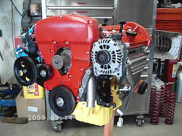
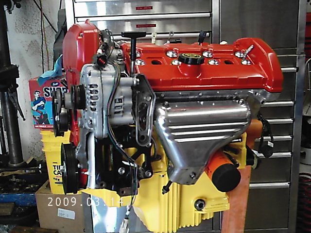
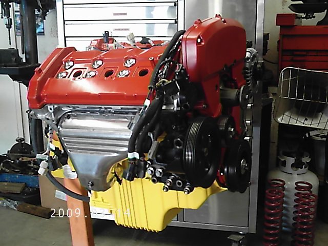
I'm sure this seems like a snails pace compared to a lot of projects out there. Been out of work for two months now so I've been focusing efforts there. I have managed to get the engine wiring harness all checked out and modified. Once its wrapped, the injectors & fuel rails go on - then its time for the intake manifold.
   |
| Maltese Falcon |
 Mar 14 2009, 06:50 PM Mar 14 2009, 06:50 PM
Post
#102
|
|
914 Guru      Group: Members Posts: 5,136 Joined: 14-September 04 From: Mulholland SoCal Member No.: 2,755 Region Association: None  |
Gerard, keep a keen eye on that oil pan, it seems like it will be a sure candidate for asphalt injections. I think you can build a suitable m/mount to take care of that.
Marty |
| 3d914 |
 Mar 18 2009, 03:24 PM Mar 18 2009, 03:24 PM
Post
#103
|
|
Senior Member    Group: Members Posts: 1,275 Joined: 24-September 03 From: Benson, AZ Member No.: 1,191 Region Association: Southwest Region |
Marty,
Yeh - that things deep, but it won't sit any lower than 1/2" below the bottom of the fire wall. Well I set aside the fear and decided to cut into the perfectly good body panel just behind the right-side door. It was the only way I could come up with to get good access to the "hell hole" and jack receiver plate. As you can see, those receivers are great for trapping water and causing rust. This side will get some new metal - maybe two panels worth. 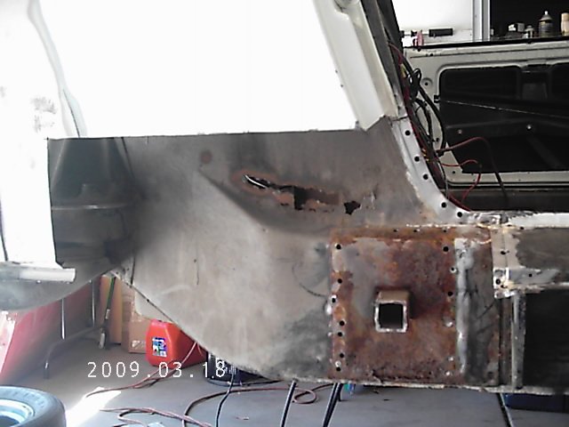 The left side still has the panel removed from all the body putty I cut out of there. All I needed to do was cut a clean edge and find a piece to replace it when I'm done with the jack receiver. 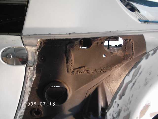 I also spent some time, with my wife's help, checking all the body measurements. Everything checked out very good - worse difference was within 1/8". Not bad for these cars. I was especially concerned since it looks like someone drover this car over a bunch of parking curbs. Nothing that can't be popped out - but at least the body is straight. Now back to the engine for a day or so. |
| RJMII |
 Mar 18 2009, 03:29 PM Mar 18 2009, 03:29 PM
Post
#104
|
|
Jim McIntosh     Group: Members Posts: 3,125 Joined: 11-September 07 From: Sandy, Utah Member No.: 8,112 Region Association: None |
Gerard,
Looking good! Is the driver side cut open to where you can get more pictures? See my thread about pics request of the 1/4s... |
| 3d914 |
 Apr 7 2009, 01:43 PM Apr 7 2009, 01:43 PM
Post
#105
|
|
Senior Member    Group: Members Posts: 1,275 Joined: 24-September 03 From: Benson, AZ Member No.: 1,191 Region Association: Southwest Region |
I've started digging more into the outer longitudinal at the jack point. It seems there were some previous residents making their home here.
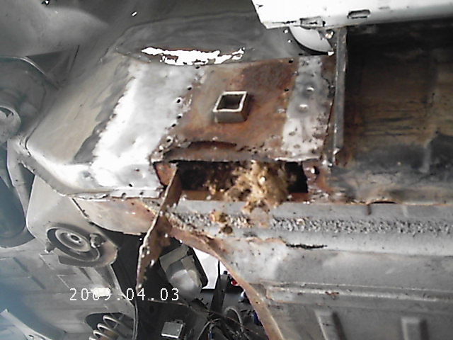 Once I finish cutting out the top of the shelf below the battery tray, I should be able to get a clearer look into the long. It appears as though there are two layers of metal, and I don't want to cut through both at the same time. I'd like to stagger the cuts and the welds. Dang - need a new cutting disk. |
| 3d914 |
 Apr 7 2009, 02:08 PM Apr 7 2009, 02:08 PM
Post
#106
|
|
Senior Member    Group: Members Posts: 1,275 Joined: 24-September 03 From: Benson, AZ Member No.: 1,191 Region Association: Southwest Region |
Don't want to run out yet to get a cutting disk, so I'm planning the cuts I need for the firewall between cockpit and engine bay.
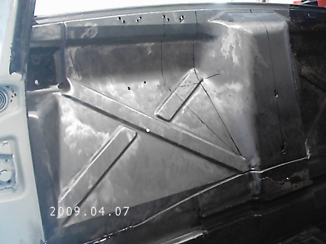 The raised middle section is what I need to widen by 8 inches (4" each side). I already have a replacement 8" wide section for the center, with all the necessary radiuses. So the plan is to work from the existing center and move each side 4" out. THe outer-most black line is the cut line for the new edge. The area between it and the second line is what will be removed. Then from the second line to the centerline will get shifted over to the new edge. They'll be another cut in the section to be moved to allow the rotation needed. I've also decided it would be better not to cut into the larger of the three reinforcing channels on each side. This means I'll have to due some angular blending between the two pieces. This should be much easier than trying to form all the radiuses. |
| 3d914 |
 Apr 7 2009, 09:10 PM Apr 7 2009, 09:10 PM
Post
#107
|
|
Senior Member    Group: Members Posts: 1,275 Joined: 24-September 03 From: Benson, AZ Member No.: 1,191 Region Association: Southwest Region |
OK, scratch out those lines.
I drove over to the garage where my engine's at to update my dimensions - and a good thing I did. I did not include the pulleys for the various accessories because they were located low enough and wouldn't interfere with the firewall - all but one. The alternator pulley will just interfere with the firewall by 1/2 inch or so. So now instead of adding 8" I'll have to add 10". That will put the pulley in the deeper portion of the firewall with an inch or more of clearance. 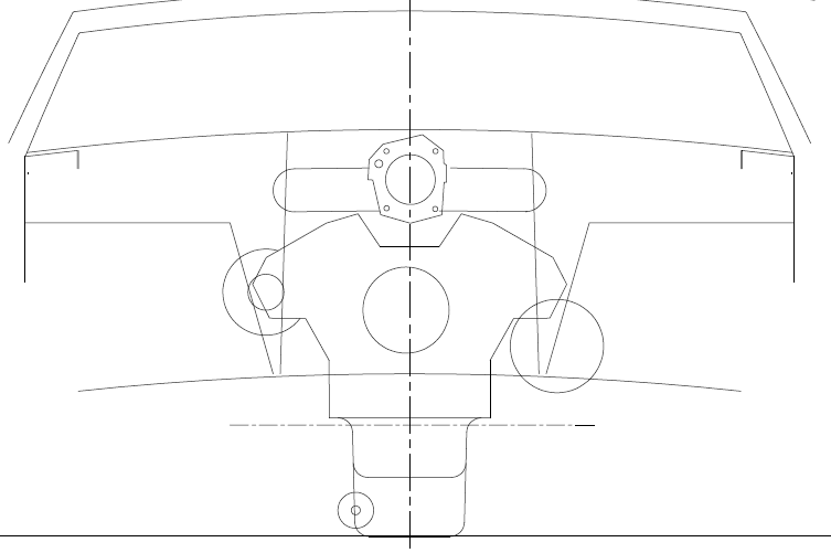 |
| 3d914 |
 Apr 26 2009, 06:45 PM Apr 26 2009, 06:45 PM
Post
#108
|
|
Senior Member    Group: Members Posts: 1,275 Joined: 24-September 03 From: Benson, AZ Member No.: 1,191 Region Association: Southwest Region |
Worked on the engine this weekend to finish up the fuel rails, injectors, and fuel lines that connect to the rails. Didn't have my camera so I'll get a pic before I install the intake early next week.
|
| 3d914 |
 Apr 26 2009, 06:59 PM Apr 26 2009, 06:59 PM
Post
#109
|
|
Senior Member    Group: Members Posts: 1,275 Joined: 24-September 03 From: Benson, AZ Member No.: 1,191 Region Association: Southwest Region |
Did get to spend some time last week cutting out the remaining rust areas around the hell-hole - with the exception of the long. I'm going to wait to finish the long until I've patched the other panels. Hopefully this will minimize the amount of weakness in this area.
I removed the upper panel above the inner long on the engine bay, a section of the inner fender above the long, and a corner section of the lower firewall. Upper panel: 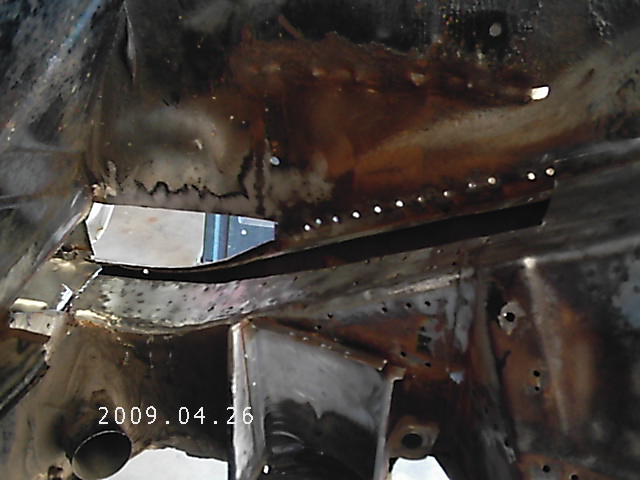 Inner fender section: 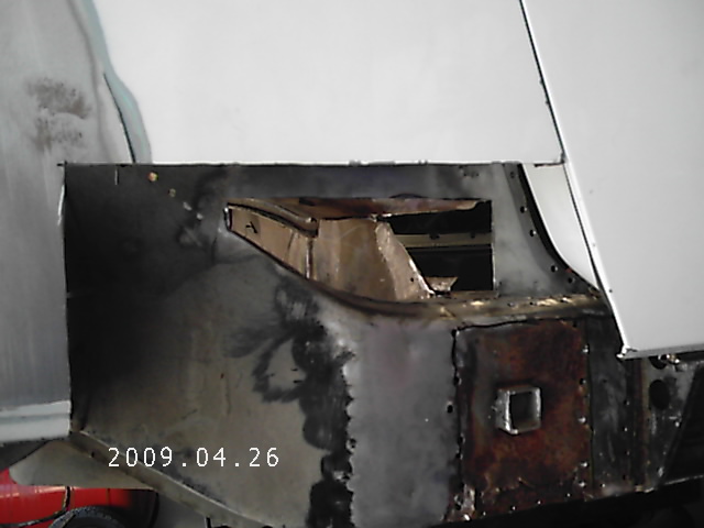 Lower firewall corner: 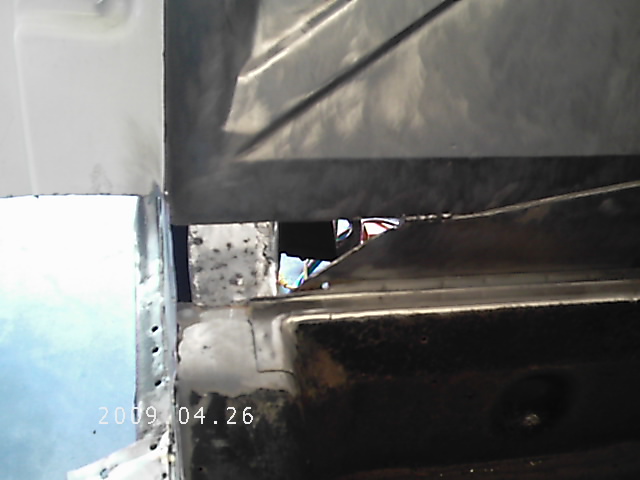 Here are the replacement pieces I cut and bent using my vise, a piece of 2x4 and a 2lb hammer. The bottom piece shown is to reinforce the wide part of the inner long. The long has holes from drilling out all the spot welds in the upper panel, so I'll place the reinforcement panel underneath the long and use the holes for welding it in place. It may not be necessary, but it's easier to do while everything's open - and I can be sure I've retained sufficient strength in that part of the long. 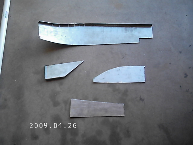 |
| 3d914 |
 Apr 26 2009, 07:16 PM Apr 26 2009, 07:16 PM
Post
#110
|
|
Senior Member    Group: Members Posts: 1,275 Joined: 24-September 03 From: Benson, AZ Member No.: 1,191 Region Association: Southwest Region |
For reference I wanted to show how the longitudinal looks from this side. The inner long is two separate pieces with a big gap at the top, and a smaller gap at the bottom.
The upper panel (or shelf) sits slightly above the inner long until it gets close to the inner curved edge. The welds from the battery tray went all the way through the shelf and into the inner long. I started removing the shelf by drilling out the spot welds that connect it to the inner fender. You can see the string of holes in the picture. I did likewise with the welds along the top face of the shelf - drilling through it and the inner long. I used my Dremel cutter to carefully cut the limits of the shelf - trying not to go all the way through. I succeeded at the upper end, but cut slightly into the inner long near the lower end - hence the reason for some additional support. I then slowly pulled the upper shelf off - pulling toward the engine bay. I had to cut it length wise a couple of times as I exposed more welds I couldn't see from the surface. Its important to drill these welds out because pulling will just rip the inner long - and thats the load-bearing portion we want to keep in tact and in good shape. Once I got the shelf out to the radius edge I was able to cut it with my 3" cutting wheel and get a decent edge. I then pounded that edge back down onto the inner long. It will be used as the mating edge for the new piece. 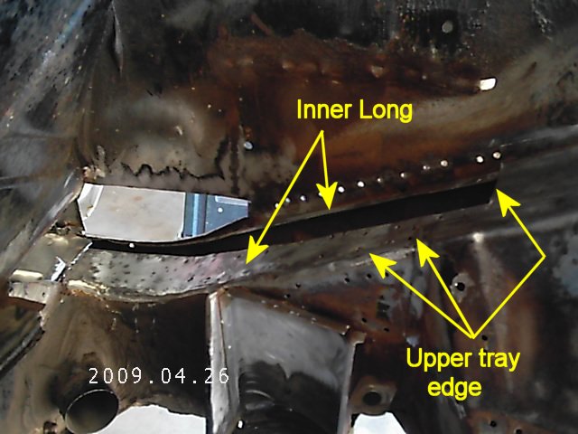 You'll notice that the engine shelf is missing. It was rusted in spots and needed to be removed anyway to get better access. It could go back on, but since I'm doing the SHO V6, I won't bother. The front and left engine shelf will get removed also just to clean things up and provide some more room. |
| 3d914 |
 May 3 2009, 09:23 PM May 3 2009, 09:23 PM
Post
#111
|
|
Senior Member    Group: Members Posts: 1,275 Joined: 24-September 03 From: Benson, AZ Member No.: 1,191 Region Association: Southwest Region |
I've managed to squeeze in some time to get the engine in its semi-final form. Purty eh?
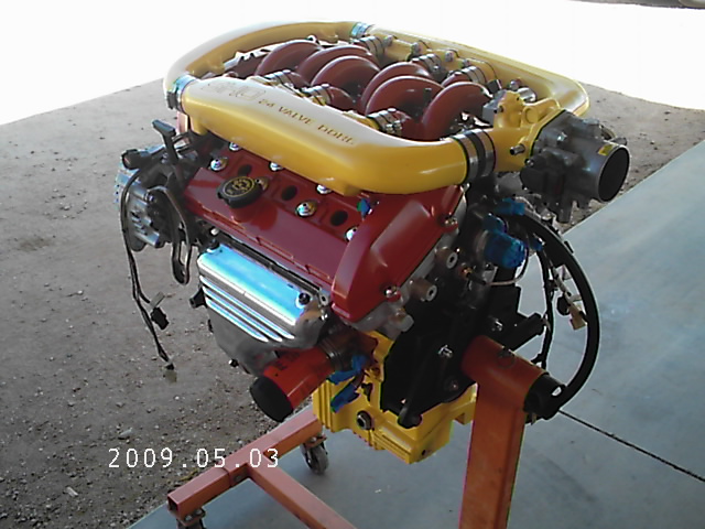 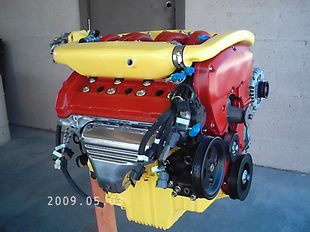 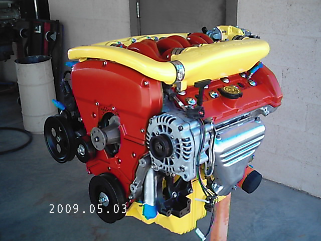 With the engine harness and intake manifold on, the remaining items are minor in comparison. However, with a pending move to southern Arizona in the next six weeks, its not likely that I will get much more done until after that. As a reminder, here are a few things left to prepare for the bench run.
The engine cradle will be another piece of work, as its going to serve a dual role. It will function as the rolling cradle for the engine, transaxle, and exhaust during the bench test. It will also serve as a lifting aid to install the engine/transaxle assembly into the car, but more on that later. I hope to get the welding done on the panels above and the rusted longitudinal repaired before the move. |
| tomeric914 |
 May 4 2009, 02:02 PM May 4 2009, 02:02 PM
Post
#112
|
|
One Lap of America in a 914!    Group: Members Posts: 1,305 Joined: 25-May 08 From: Syracuse, NY Member No.: 9,101 Region Association: North East States 
|
|
| 3d914 |
 Jan 2 2010, 09:56 AM Jan 2 2010, 09:56 AM
Post
#113
|
|
Senior Member    Group: Members Posts: 1,275 Joined: 24-September 03 From: Benson, AZ Member No.: 1,191 Region Association: Southwest Region |
Just a quick update. The car is sitting, covered, outside the garage for the moment. I relocated to Benson, AZ back in May starting a new job, bought a new house in September and am still settling in.
On top of that the 924S is down for some new rings, so it will be a while before I get back to the teener. ENjoy! |
| Mike Bellis |
 Mar 16 2011, 08:40 PM Mar 16 2011, 08:40 PM
Post
#114
|
|
Resident Electrician      Group: Members Posts: 8,347 Joined: 22-June 09 From: Midlothian TX Member No.: 10,496 Region Association: None 

|
We need an update! (IMG:style_emoticons/default/smile.gif)
|
| Eric_Shea |
 Mar 16 2011, 09:10 PM Mar 16 2011, 09:10 PM
Post
#115
|
|
PMB Performance                Group: Admin Posts: 19,304 Joined: 3-September 03 From: Salt Lake City, UT Member No.: 1,110 Region Association: Rocky Mountains  |
No (IMG:style_emoticons/default/stromberg.gif)
That is one of THE nicest engines on the planet. Would love to see a teener tooling around with one of those in there. |
| 3d914 |
 Aug 21 2011, 03:54 PM Aug 21 2011, 03:54 PM
Post
#116
|
|
Senior Member    Group: Members Posts: 1,275 Joined: 24-September 03 From: Benson, AZ Member No.: 1,191 Region Association: Southwest Region |
Just an update. Finally got the garage free from kid's cars (924S & 914) and rolled the project 914 in. With the rainy season down on us, I was glad to get it out from under the tarp and into the dry garage. Still haven't started back on it, as I have to get my cabinets built so that I can work in my garage.
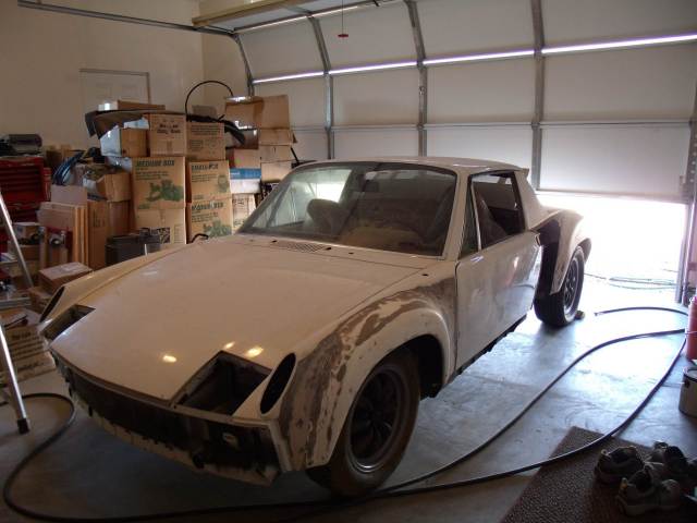 For anyone looking for a similar project, I came up with a very efficient cabinet design - which minimizes materials & maximizes storage space. Since this is related to the project - and it's the only thing I'm working on right now - I'll divert and share the design & progress. |
| 3d914 |
 Aug 21 2011, 04:13 PM Aug 21 2011, 04:13 PM
Post
#117
|
|
Senior Member    Group: Members Posts: 1,275 Joined: 24-September 03 From: Benson, AZ Member No.: 1,191 Region Association: Southwest Region |
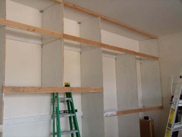
Along the west side of my garage I have nearly 24 feet of wall space, and have already designed some built-in cabinets. These cabinets start one foot above the floor and extend 9-1/2 feet to the ceiling. The upper most sections will be open without doors to use for body parts like bumpers and exhaust pieces. They're 24 inches deep, so they provide a lot of storage area.
 I left two sections at the ends open to the floor to allow storage of vertical items and some hand tools. These two sections and the center (open section) will get peg-board that will be used as a mounting medium for various hangers. 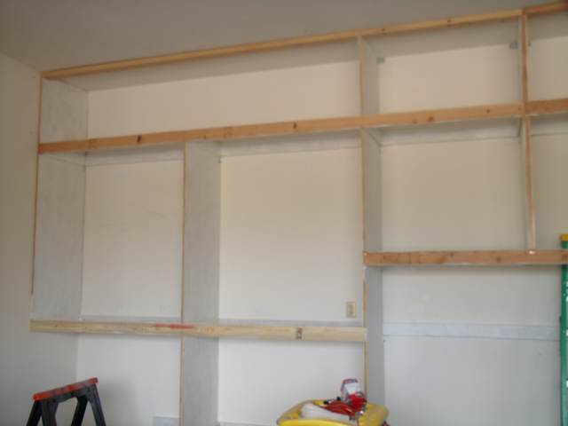 I'm quite pleased with the design, as my goal was to provide a maximum of storage space at a more reasonable cost compared to cabinet components sold at the local home improvement stores. They build sectional units that you connect together. The drawback is all the duplicate side-walls and backs you end up with. I eliminate all that by building then right onto the back & side walls of the garage. I begin with 2x4 stringers, screwed to the wall studs, and run horizontally at the bottom, middle, and top of the cabinets. End panels are fastened to the side walls at the studs, and are notched for the stringers. These end panels, together with the stringers, support the cabinet frame. To provide additional support, metal legs are added at the front of the cabinets and extend to the floor to alleviate side loads on the back wall. 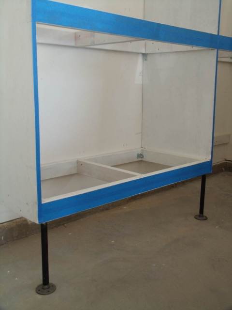 At this point everything is primed and ready for paint. The unpainted portion of the stringers doesn't get primer since I'll be gluing and fastening the faces to the framework. I've also taped those mating surfaces in preparation for paint. 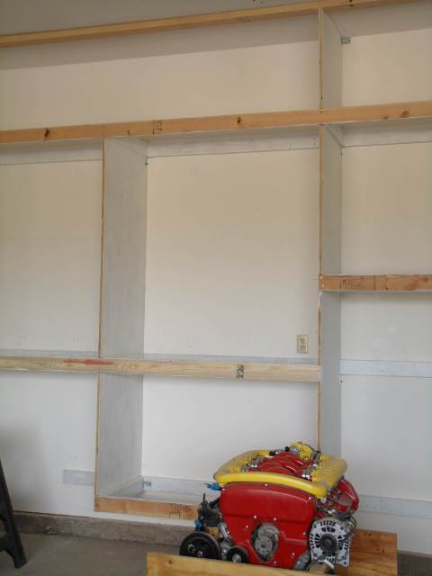 |
| 3d914 |
 Sep 7 2011, 10:59 PM Sep 7 2011, 10:59 PM
Post
#118
|
|
Senior Member    Group: Members Posts: 1,275 Joined: 24-September 03 From: Benson, AZ Member No.: 1,191 Region Association: Southwest Region |
Well I've made decent progress on the cabinets - which should make it easier to get to the 914. Cabinets aren't done, but at least everything is off the floor and I have room for both cars again. Just in time to get side-tracked for a couple of weeks to put up a fence.
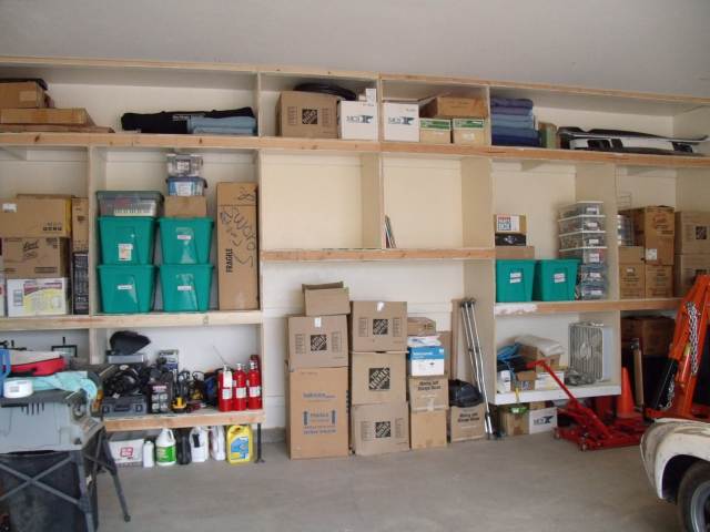 Hey, but at least the 914 is in the garage and in the right spot. I know - it needs to be up on jack stands. Be patient, I'm getting there. (IMG:style_emoticons/default/smile.gif) 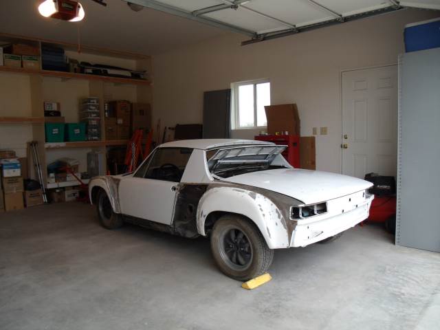 |
| 3d914 |
 Sep 15 2011, 09:42 PM Sep 15 2011, 09:42 PM
Post
#119
|
|
Senior Member    Group: Members Posts: 1,275 Joined: 24-September 03 From: Benson, AZ Member No.: 1,191 Region Association: Southwest Region |
Started back to work on the 914 removing parts, cleaning the parts I'll keep and putting away on shelves. I removed the remaining roll-bar trim and windshield inner trim and rubber. No surprises here.
Also went around the doors and decided to investigate a peculiar behavior. If I close either door till I hear the "clunk" all is fine and the outer surface of the door lines up nicely with the outer surface of the rear quarter panel. (I'll call this position one) If I push the door a little more it continues to close further and I end up with a very ugly gap between the door and quarter panel. (I'll call this position two) 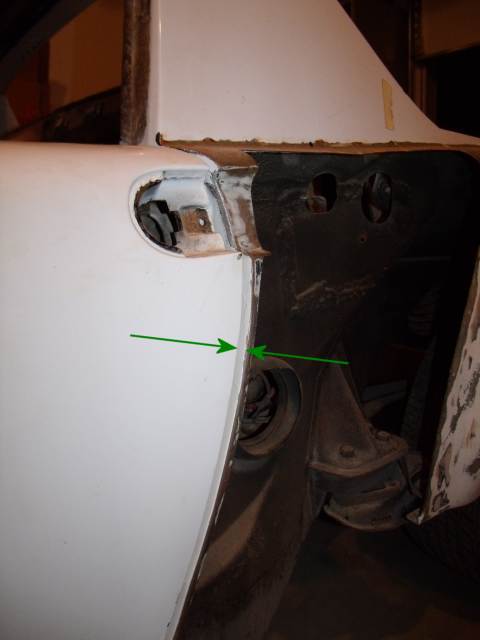 When I inspected the door latch I noticed that at initial closure the locking cam lines up almost vertically. I associate this with position one. 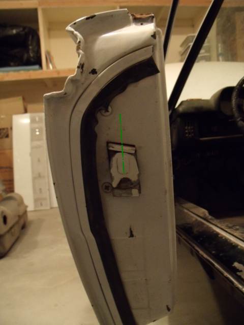 Yet I'm able to rotate it further, which I associate with position two. 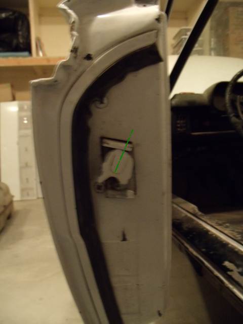 I haven't taken the mechanism apart yet, but can the internal stop for the locking cam wear that much, or is there something else I'm not seeing? |
| Mike Bellis |
 Sep 15 2011, 09:56 PM Sep 15 2011, 09:56 PM
Post
#120
|
|
Resident Electrician      Group: Members Posts: 8,347 Joined: 22-June 09 From: Midlothian TX Member No.: 10,496 Region Association: None 

|
Adjust the position of the strike on the door jam. Door latch looks fine.
|
  |
1 User(s) are reading this topic (1 Guests and 0 Anonymous Users)
0 Members:

|
Lo-Fi Version | Time is now: 15th January 2026 - 08:10 PM |
Invision Power Board
v9.1.4 © 2026 IPS, Inc.


