|
|
|
Porsche, and the Porsche crest are registered trademarks of Dr. Ing. h.c. F. Porsche AG.
This site is not affiliated with Porsche in any way. Its only purpose is to provide an online forum for car enthusiasts. All other trademarks are property of their respective owners. |
|
|

  |

| 3d914 |
 Nov 12 2011, 11:17 PM Nov 12 2011, 11:17 PM
Post
#141
|
|
Senior Member  Group: Members Posts: 1,275 Joined: 24-September 03 From: Benson, AZ Member No.: 1,191 Region Association: Southwest Region |
Well I'm confused then. What happens to all the low pressure air flowing underneath the car? It would create a higher pressure shortly after the fire wall without something to continue it to the rear valance.
|
   |

 
|
| Mike Bellis |
Nov 12 2011, 11:31 PM
Post
#142
|
|
Resident Electrician Group: Members Posts: 8,348 Joined: 22-June 09 From: Midlothian TX Member No.: 10,496 Region Association: None |
The air under the car would actually create a low pressure area in the engine compartment due to venturi effect as the air travels to the rear of the car.
|
|
|
|
| 3d914 |
Nov 23 2011, 10:11 PM
Post
#143
|
|
Senior Member Group: Members Posts: 1,275 Joined: 24-September 03 From: Benson, AZ Member No.: 1,191 Region Association: Southwest Region |
Well the whole mid-mounted radiators may be mute point, as I've been working on engine mounting configurations. Here's my first configuration based on the biscuit style mounts. I'm using a 1-1/2" sq tube horizontally across the mount points.There is a 1/4" flange welded in at each end to conform to the surface of the mount. The angled pieces are 1" sq tube up to a 1/4" plate.
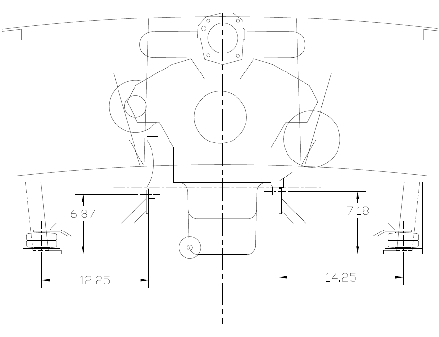 The bar is installed from the front, after the engine is in position, as the back of the receivers block the bar. I can use this config to improve installation using the rolling engine test stand I'm designing. It will have a set of rigid mounting brackets that approaches from behind the engine bar's position. On the left it will mount to the same points but at the back side. On the right it will mount to two mounting holes that are slightly higher and extended. I'll think about a couple more possibilities, but I think this looks like it will work best. There is plenty of clearance for the shift rod, and it sits forward of the exhaust headers. The centerline where I positioned the engine turned out to be precisely where the center of the engine bar would be - too cool! |
|
|
|
| 3d914 |
Nov 26 2011, 05:39 PM
Post
#144
|
|
Senior Member Group: Members Posts: 1,275 Joined: 24-September 03 From: Benson, AZ Member No.: 1,191 Region Association: Southwest Region |
OK, did some additional thinking and came up with another mounting option that enables me to still work for the rear-mounted mini-radiators, and also enables me to install the engine using an engine cradle design I'm modifying.
Here's what it looks like from the rear. Green is the engine bar with vertical 1/4" plates supported by 1/4" gussets. The dark red is the vertical support bar for the engine cradle, and the orange is the mounting bracket on the engine block. I have the gussets facing inward to allow space for the mini-radiators to the outside. 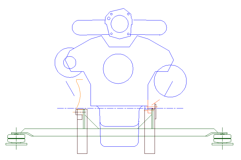 The right side shows four mounting holes. The two upper are spares used for the cradle vertical support bar. The lower two are for the engine bar. The cradle support attaches from the rear, allowing the engine to be move into position and the engine bar installed from the front. 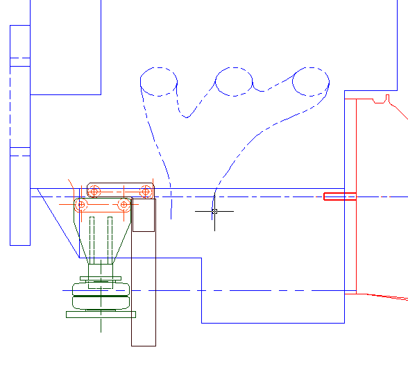 The left vertical support for the cradle required a slight 1" sq. extension added to support that side of the engine when the mounting plate is removed (Two thru holes for the vertical support and two for the block with bolts form the outside). Once the cradle's mounting plate is removed the engine bar's plate can be slid into place and bolted up from the inside. 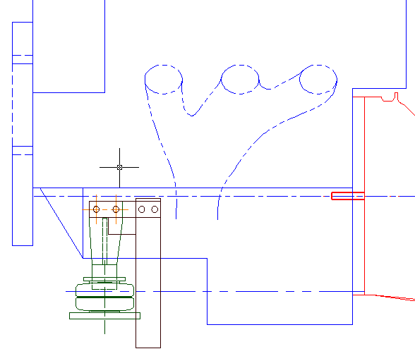 Next job is to gather the needed material and start fabbing the engine cradle and engine bar. |
|
|
|
| Mike Bellis |
Nov 26 2011, 07:00 PM
Post
#145
|
|
Resident Electrician Group: Members Posts: 8,348 Joined: 22-June 09 From: Midlothian TX Member No.: 10,496 Region Association: None |
With the design of your bar, it looks difficult to drop the engine and tranny without dropping the mounting bar first. That will make it more challenging to fuch with the engine.
|
|
|
|
| 3d914 |
Nov 27 2011, 11:34 AM
Post
#146
|
|
Senior Member Group: Members Posts: 1,275 Joined: 24-September 03 From: Benson, AZ Member No.: 1,191 Region Association: Southwest Region |
Mike, right, but that's intentional. The cradle I've redesigned will be moved into position and connected up before the engine bar is removed. The cradle supports the engine & tranny while the engine bar is removed and the cradle is fastened up. The engine bar exits the from the front of the engine.
The cradle is also designed to fit with my ATV lift. Of course the radiator supports are removed for engine install. 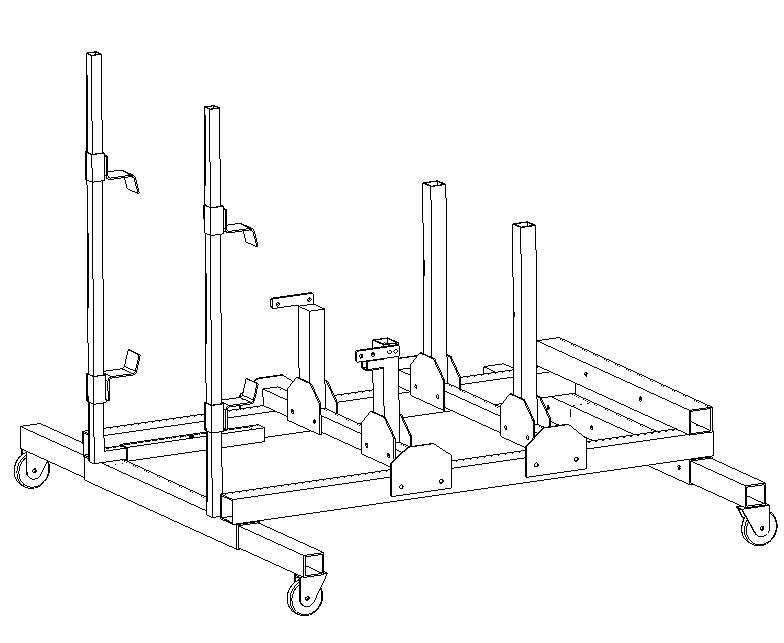 Bought the basic cradle design on line from Russ Green. |
|
|
|
| Mike Bellis |
Nov 27 2011, 01:07 PM
Post
#147
|
|
Resident Electrician Group: Members Posts: 8,348 Joined: 22-June 09 From: Midlothian TX Member No.: 10,496 Region Association: None |
Can the cradle be put in place before the engine bar is removed? If not, how do you hold the motor up ahilw installing the cradle?
|
|
|
|
| 3d914 |
Nov 27 2011, 01:58 PM
Post
#148
|
|
Senior Member Group: Members Posts: 1,275 Joined: 24-September 03 From: Benson, AZ Member No.: 1,191 Region Association: Southwest Region |
Mike, read previous.
|
|
|
|
| 3d914 |
Dec 3 2011, 09:45 AM
Post
#149
|
|
Senior Member Group: Members Posts: 1,275 Joined: 24-September 03 From: Benson, AZ Member No.: 1,191 Region Association: Southwest Region |
Came up with a bracket design for the engine cradle that supports the tranny just behind where it mounts to the adapter plate and motor.
Here's a pic of the brackets on the cradle. I save locating the mounting holes until everything is located at assembly. Portions of the cradle are hidden for clarity. 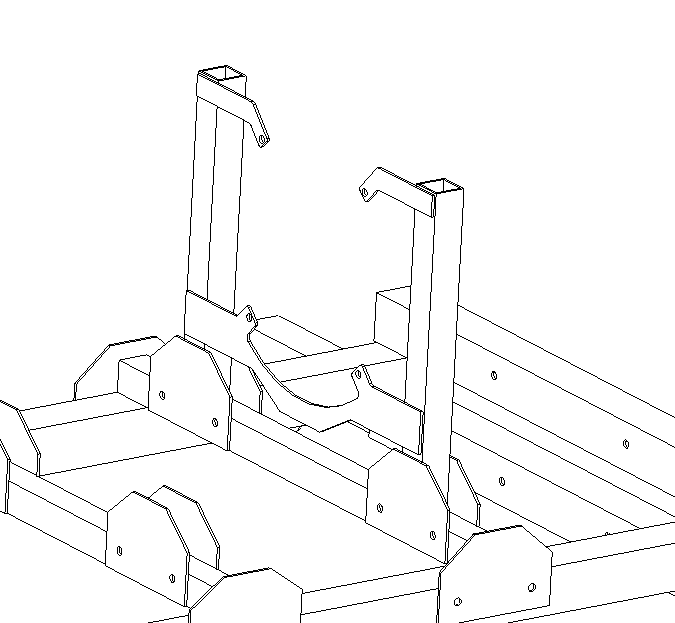 Been getting quotes for steel to fab the cradle and engine bar. Hope to have all the material together and assembly started by end of December. |
|
|
|
| 3d914 |
Dec 3 2011, 06:27 PM
Post
#150
|
|
Senior Member Group: Members Posts: 1,275 Joined: 24-September 03 From: Benson, AZ Member No.: 1,191 Region Association: Southwest Region |
Didn't get much done today - the weather turned crappy & cold. Did manage to get my door supports finished.
Had to find these heim joints with big enough thread (5/8-3/4) to fit inside the 1" sq tube without to much slop. 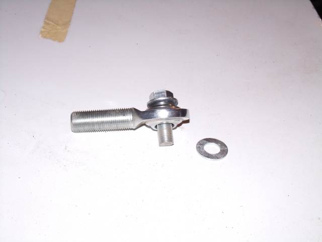 I tried going thru the 1" square tube first, but it didn't want to swing over where I could weld it to the top of the long. The angle bracket is welded on two sides, and another nut & washer will go on the back side. 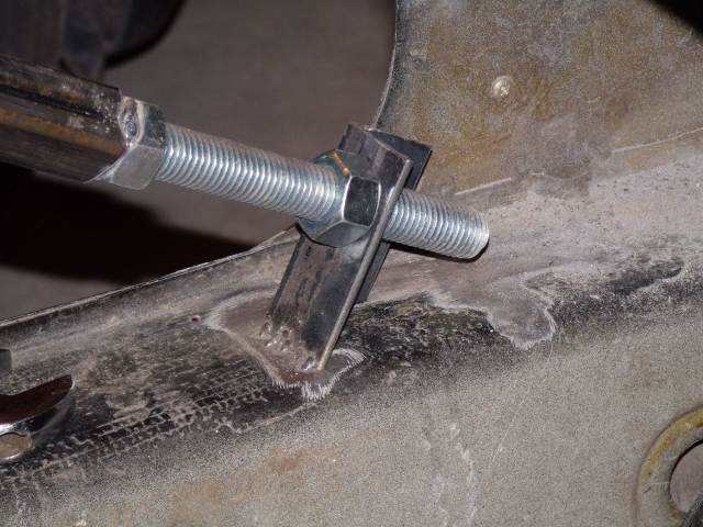 Here's the heim joint end connected to the upper safety belt mount point. 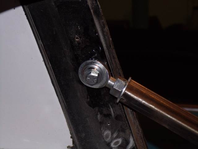 |
|
|
|
| 3d914 |
Dec 4 2011, 02:35 PM
Post
#151
|
|
Senior Member Group: Members Posts: 1,275 Joined: 24-September 03 From: Benson, AZ Member No.: 1,191 Region Association: Southwest Region |
Well my old Craftsman compressor died a week or so back, so it was time to up the ante. Since I want to increase the level of tasks I take on with this project, it made sense to upgrade one of the main tools as well. I can now consider taking on all the base primer work - instead of relying soley on canned primer.
Now I just have to find someone locally to assist with the electrical circuit. 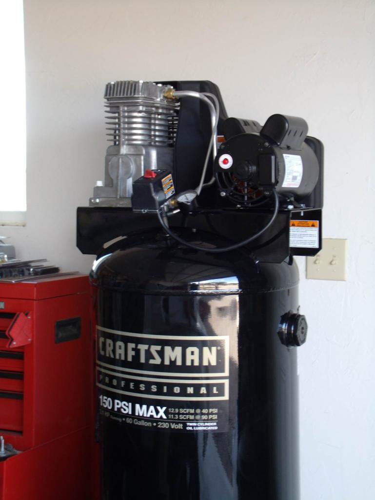 |
|
|
|
| 3d914 |
Dec 24 2011, 11:08 AM
Post
#152
|
|
Senior Member Group: Members Posts: 1,275 Joined: 24-September 03 From: Benson, AZ Member No.: 1,191 Region Association: Southwest Region |
QUOTE(SirAndy @ Nov 11 2011, 04:38 PM)  QUOTE(3d914 @ Nov 11 2011, 03:30 PM) With all the air flow under the car I would think there would be sufficient - but as you say the trick will be getting it directed to the radiators. The stock air deflectors might be helpful in disrupting the high pressure air underneath and allowing it to be drawn into the engine bay. I'm pretty sure with the air deflectors, the pressure would be going the opposite way. The deflectors help drawing air away from the engine compartment, not into it. Unless you have some scoops under then car, your airflow would have to be reversed. Meaning the fans should suck air from the top through the radiators. Either way, I'm not sure you'll get enough pressure differential for some good air-flow. (IMG:style_emoticons/default/idea.gif) Andy, you're right. I met with a buddy of mine in Phoenix (Tim) who's been racing 914s for many years and he's saying the same thing. He did some tests with air flow from the roof across the engine lid and down the trunk. He noticed that the engine bay draws in air from the first 12" of adjacent trunk lid area. To make this work I'll need to do the following:
The guy I'm working with on the SHO motor (Tom) was concerned about the dual radiators since he's seen an install that didn't work. I asked if the guy ran them separately or in series. He recalls them being separate - which I agree would pose a problem - this is why I'm running them in series. The output from the one radiator will feed the inlet for the other - ensuring the needed volume/surface area is covered. |
|
|
|
| 3d914 |
Dec 27 2011, 06:36 PM
Post
#153
|
|
Senior Member Group: Members Posts: 1,275 Joined: 24-September 03 From: Benson, AZ Member No.: 1,191 Region Association: Southwest Region |
Spent the weekend & Monday working on my son's 914. Pulling the engine to reseal everything.
I said I'd never pull another 914 engine without the use of a lift. Never say never. It went pretty well - except that he needs seals bad so everything is an oily mess. 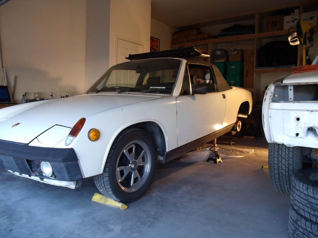 It occurred to me that since I was building an engine cradle for the SHO project, it wouldn't be much effort to build supports that would work with the 914 engine & transaxle. I could have them done before the engine is ready to go back in. Did manage to get some time in on the engine cradle - one of the side benefits of my son's infatuation with games. Spent the morning cutting, beveling, and cleaning pieces for the base, and the caster extensions. 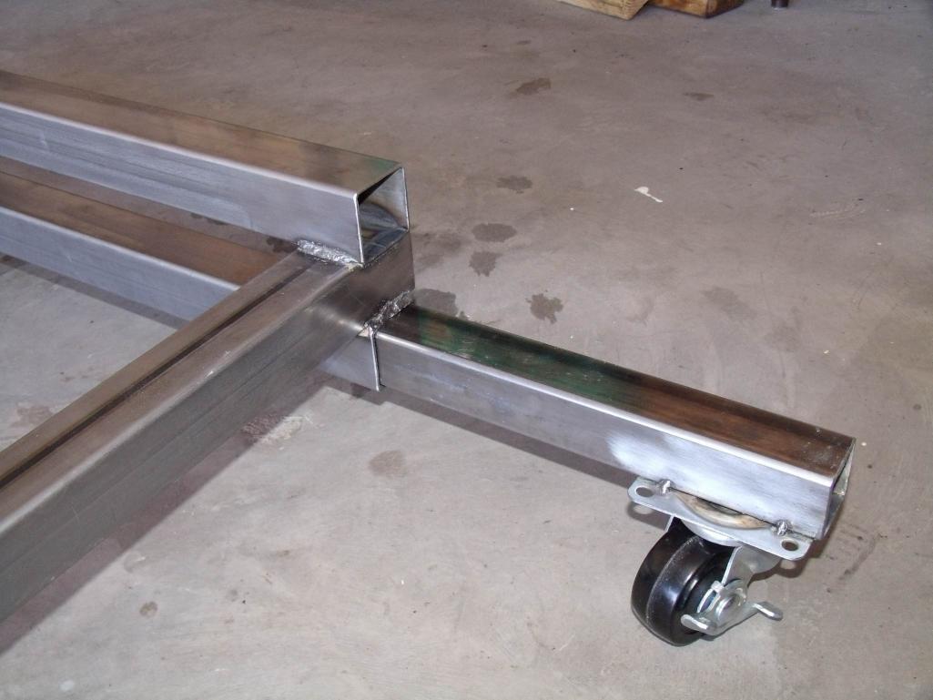 Got the base welded together and ran out of welding wire just as my son showed up. 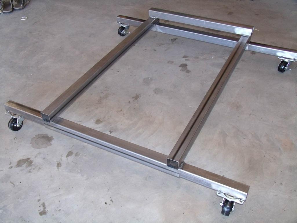 |
|
|
|
| 3d914 |
Dec 29 2011, 03:48 PM
Post
#154
|
|
Senior Member Group: Members Posts: 1,275 Joined: 24-September 03 From: Benson, AZ Member No.: 1,191 Region Association: Southwest Region |
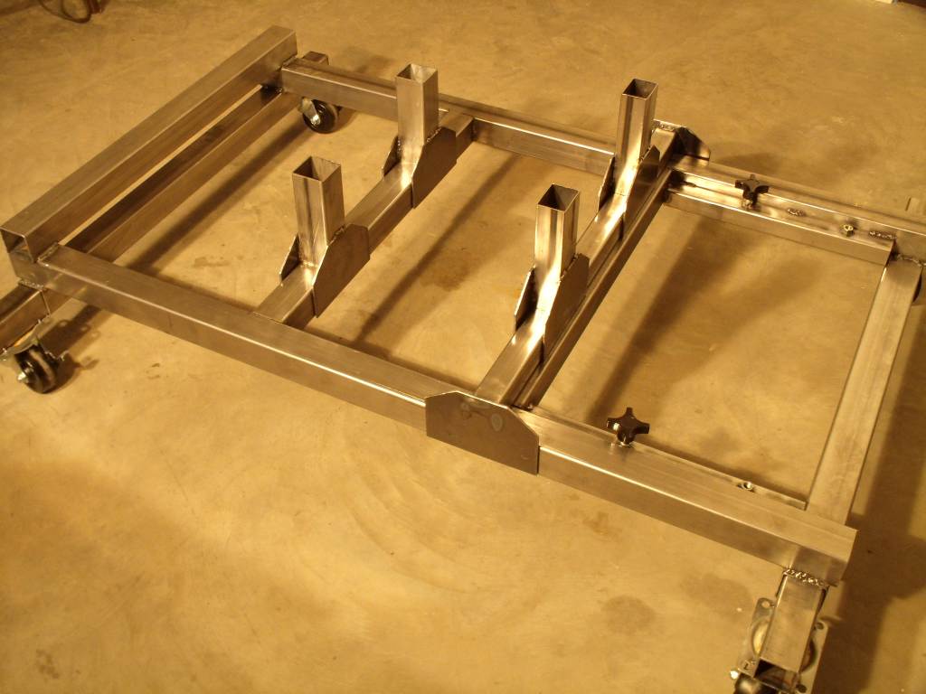
Got more done on the engine cradle today. Added the radiator support brackets, built the supports. Also added the cross-supports that match my ATV lift.
Next are the support tubes for the engine. I found a place that will plasma cut my brackets for reasonable price. Gotta put each in a DXF file though - good thing I got CAD. 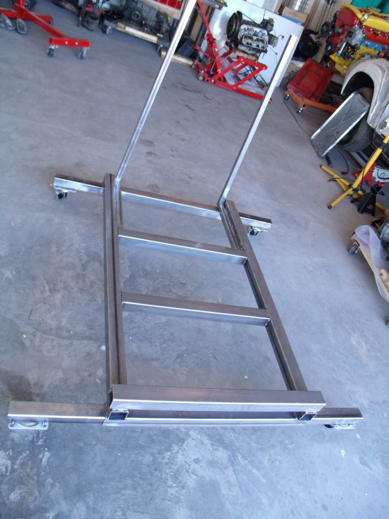 |
|
|
|
| 3d914 |
Jan 8 2012, 06:07 PM
Post
#155
|
|
Senior Member Group: Members Posts: 1,275 Joined: 24-September 03 From: Benson, AZ Member No.: 1,191 Region Association: Southwest Region |
Been working more on the engine cradle while waiting on parts for my son's 914. Have the horizontal and vertical supports done for the SHO motor. It's actually starting to look like an engine stand.
 The mating brackets for the engine are going to be plasma cut by a shop in Tucson. The varied shapes and steel thickness was beyond my hand tools. Once their done, I'll get them test fit and attached. This has been a good welding exercise. I ran out of the good Lincoln flux core wire and tried some from the local ACE hardware. No comparison, this ACE stuff makes flux welding a B!#&%*!. Ten times the cleanup as the Lincoln flux core. Guess I'll hunt for good stuff and put the other on the shelf for emergencies. |
|
|
|
| 3d914 |
Jan 24 2012, 06:54 PM
Post
#156
|
|
Senior Member Group: Members Posts: 1,275 Joined: 24-September 03 From: Benson, AZ Member No.: 1,191 Region Association: Southwest Region |
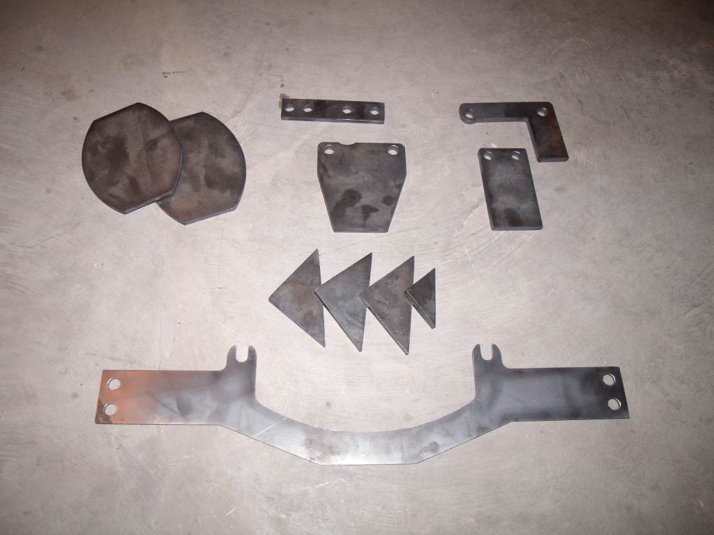
Hoo Raa! The parts for the cradle and engine bar came in from the plasma cutter. Looks like I'll get to do some more welding this week.
 |
|
|
|
| AZ914 |
Jan 25 2012, 08:00 AM
Post
#157
|
|
914 Dumbass Group: Members Posts: 1,469 Joined: 6-January 03 From: Sunny Tucson Member No.: 98 Region Association: Southwest Region |
Lookin good!
|
|
|
|
| ThePaintedMan |
Jan 25 2012, 09:10 AM
Post
#158
|
|
Advanced Member Group: Members Posts: 3,887 Joined: 6-September 11 From: St. Petersburg, FL Member No.: 13,527 Region Association: South East States |
Wow, what a thread! Very cool Gerard. No offense, but if I were your son, I would be out there workin on the car with you rather than computer games! My dad helped me get my old Thunderbird back on the road when I was in high school, but he had nowhere near the ability that you have. Plus, its a 914, which as much as I hate to admit it, is much cooler than the T-Bird (IMG:style_emoticons/default/smile.gif)
-George |
|
|
|
| ThePaintedMan |
Jan 25 2012, 02:32 PM
Post
#159
|
|
Advanced Member Group: Members Posts: 3,887 Joined: 6-September 11 From: St. Petersburg, FL Member No.: 13,527 Region Association: South East States |
Wow, what a thread! Very cool Gerard. No offense, but if I were your son, I would be out there workin on the car with you rather than computer games! My dad helped me get my old Thunderbird back on the road when I was in high school, but he had nowhere near the ability that you have. Plus, its a 914, which as much as I hate to admit it, is much cooler than the T-Bird (IMG:style_emoticons/default/smile.gif)
-George |
|
|
|
| 3d914 |
Jan 25 2012, 08:43 PM
Post
#160
|
|
Senior Member Group: Members Posts: 1,275 Joined: 24-September 03 From: Benson, AZ Member No.: 1,191 Region Association: Southwest Region |
Hey Jason, you're still in Tucson right? We should get together sometime. i tried a couple of times to connect with Guy also, but kept missing him. I'm forty minutes east in Benson.
Thanks George. Since he's in the Marines and typically works 10-hours day or more, I don't give him too much sh#t about the game time. He's only able to make it out here when he has 72 or 96-hour leave. Yeh, Tbirds are boats, but they're cool boats. My Dad had two, a 65 & a 68 IIRC. Well I decided to ditch the radiators mounted at the engine bar and drawing air from underneath. I would have to force more air under the car - which is undesirable - and the shrouds would have to sit below the body & would be a candidate for speed bump fodder. After spending some time discussing it with a 914 racer friend of mine who has studied the air flow of the 914 at the roof/engine lid/trunk area, we've concluded the best approach in the engine bay is this. 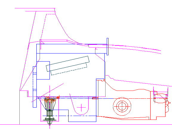 The advantage of this location makes use of the air being drawn into the top of the engine bay. Tests ran by Tim showed that air pulls off the top and into the engine bay, and also pulls forward from the front 12 inches of the trunk lid. I'll have to modify my engine lid from the standard, which is half painted metal and half metal mesh, to a GT style lid that is all mesh. Here's the twin rad placement from the rear. 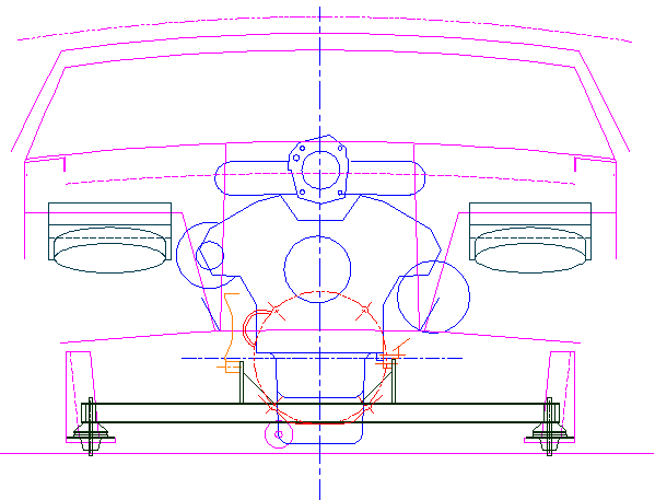 |
|
|
|
|
1 User(s) are reading this topic (1 Guests and 0 Anonymous Users)
0 Members:

|
Lo-Fi Version | Time is now: 24th June 2026 - 04:29 PM |
Invision Power Board
v9.1.4 © 2026 IPS, Inc.