|
|
|
Porsche, and the Porsche crest are registered trademarks of Dr. Ing. h.c. F. Porsche AG.
This site is not affiliated with Porsche in any way. Its only purpose is to provide an online forum for car enthusiasts. All other trademarks are property of their respective owners. |
|
|

  |

| 3d914 |
 Jun 10 2012, 02:21 PM Jun 10 2012, 02:21 PM
Post
#181
|
|
Senior Member  Group: Members Posts: 1,275 Joined: 24-September 03 From: Benson, AZ Member No.: 1,191 Region Association: Southwest Region |
Finished up the weld and grinding. Tried out one of the 3M abrasive pads today. I like the finish it provides, and it doesn't heat up the metal the way the grinder pad does. So I've been using both, one on the pneumatic die-grinder the other on my electric grinder. I use the grinding pad to get the welds down to the metal, then use the abrasive pad to clean it up.
 The few spots remaining to the left are outside the butt-weld. I was just filling in low spots on the adjacent piece - no end to it though. |
   |

 
|
| 3d914 |
Jun 15 2012, 04:32 PM
Post
#182
|
|
Senior Member Group: Members Posts: 1,275 Joined: 24-September 03 From: Benson, AZ Member No.: 1,191 Region Association: Southwest Region |
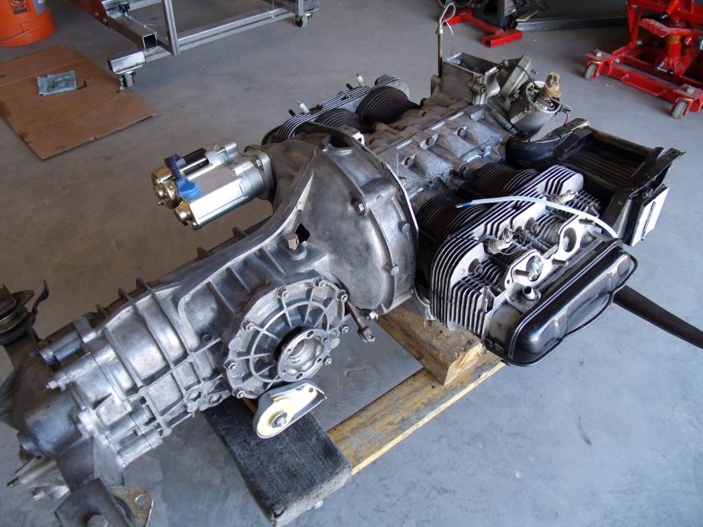
Worked on my son's 914 today. Found all the parts to assemble the engine & tranny. Always seem to have to go to the hardware store for new washers. It's gettin there.
 |
|
|
|
| 3d914 |
Jun 17 2012, 05:17 PM
Post
#183
|
|
Senior Member Group: Members Posts: 1,275 Joined: 24-September 03 From: Benson, AZ Member No.: 1,191 Region Association: Southwest Region |
With the outer long done, I went back to finish up the longitudinal shelf section under the battery tray. I had this welded up, but didn't do the finish work. Now with a working compressor again I was able to get this cleaned up.
I still have to replace a section where the battery tray mounted, but I've got some surface rust to deal with and decide what needs to be cut out. 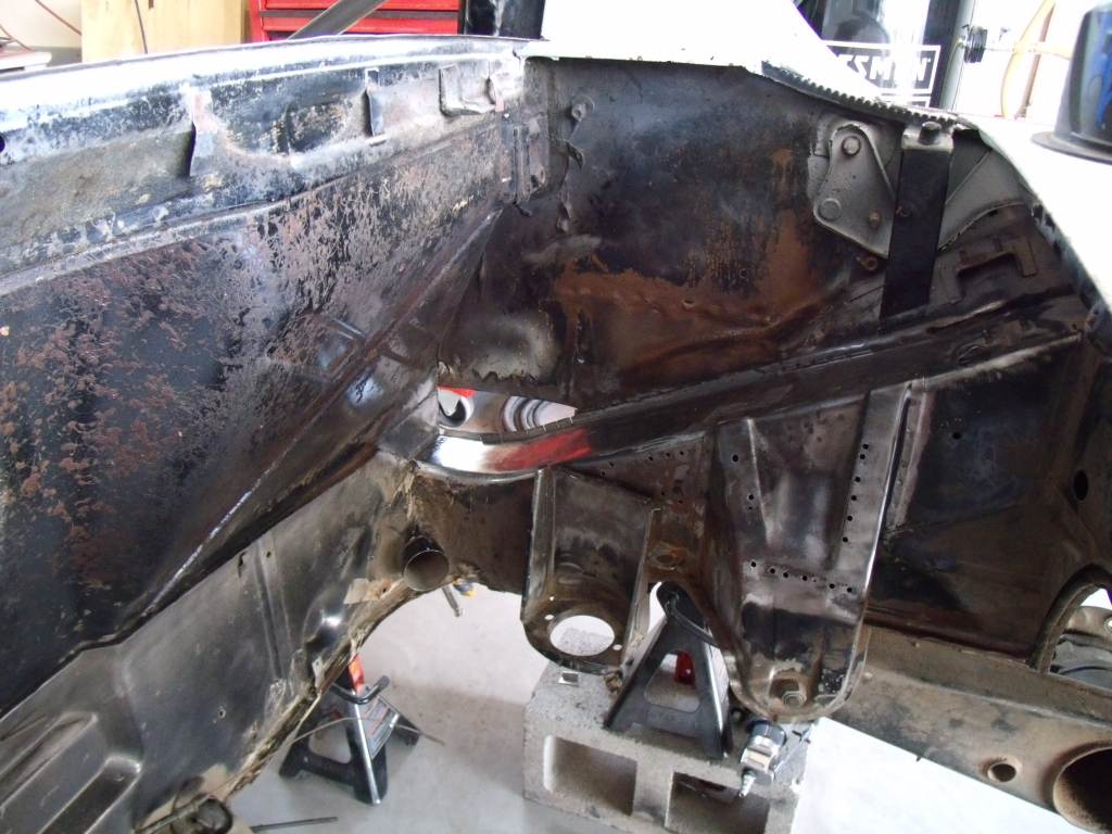 I also had some time to cut off the center shelf section. It worked well to cut from underneath, using the edge of the lower piece as a guide. I'll add a few more spot welds and likely weld the edge of the two pieces together at the seam. 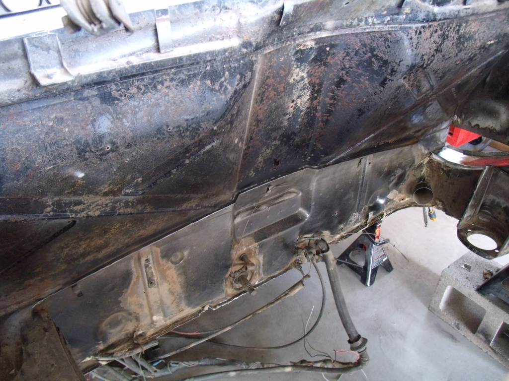 |
|
|
|
| 3d914 |
Jun 22 2012, 05:19 PM
Post
#184
|
|
Senior Member Group: Members Posts: 1,275 Joined: 24-September 03 From: Benson, AZ Member No.: 1,191 Region Association: Southwest Region |
I decided to finally fill all the holes in the longs left from removing the shelf. I've been using a technique to accommodate the limitations of my welder. It enabled me to weld up holes in the single ply sheetmetal without blowing through.
So here's what I'm starting with - holes in the longs from using an angled drill to drill out spot welds. 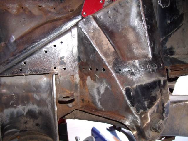 Since I know there are other teener owners out there in the same situation, I thought I'd share the technique. I've seen others accomplish this with sheet-metal plugs, but the problem then is holding the small plug in place while you weld. I decided instead to use steel nails whose heads were the same diameter as my holes. Here's what I found. These have a galvanized cap on them but the nail is steel (w/o galvanizing). I just push the cap off. May be I'll find something useful to do with them. 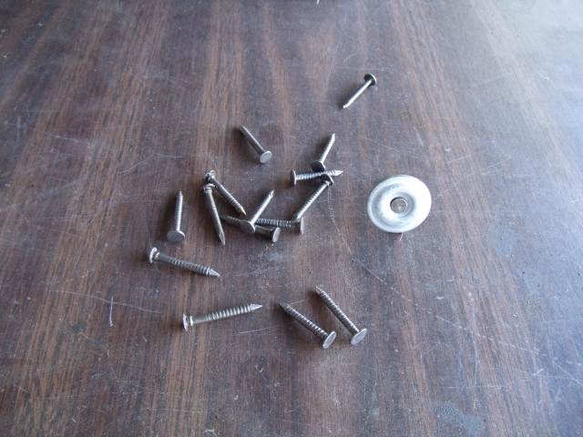 Next, I position the nails so the heads fill the holes and the protruding nail is held in place with a small welding magnet. I picked these up from HF. 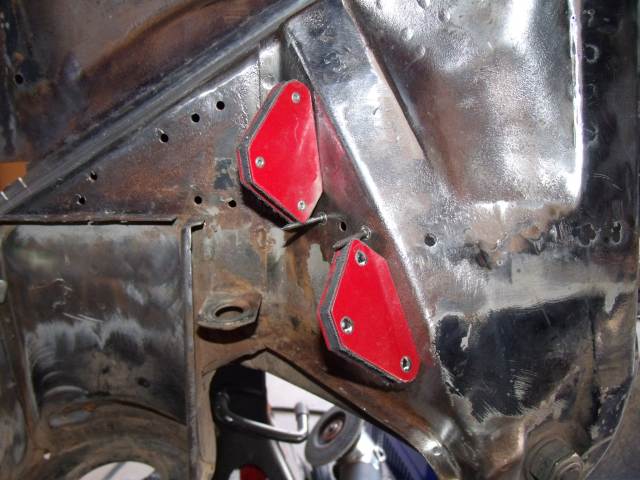 |
|
|
|
| 3d914 |
Jun 22 2012, 05:25 PM
Post
#185
|
|
Senior Member Group: Members Posts: 1,275 Joined: 24-September 03 From: Benson, AZ Member No.: 1,191 Region Association: Southwest Region |
Then, I do the first weld to secure the nail so I can remove the magnet.
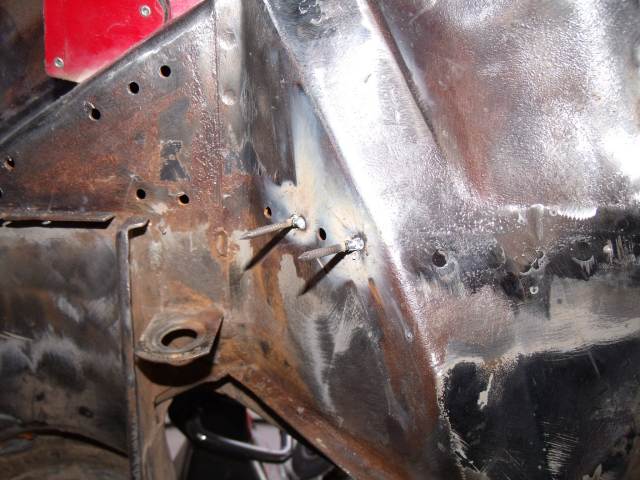 That let's me get all around the nail to complete the weld. 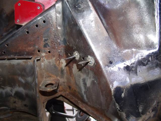 Lastly, I grind off the nail and grind down the weld with a disc grinder. I'll use a 3M abrasive pad later to finish up with. 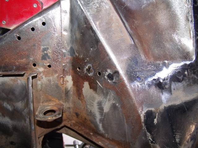 |
|
|
|
| 3d914 |
Jun 22 2012, 05:29 PM
Post
#186
|
|
Senior Member Group: Members Posts: 1,275 Joined: 24-September 03 From: Benson, AZ Member No.: 1,191 Region Association: Southwest Region |
If the holes are too small, I just match my drill to the nail heads and re-drill them.
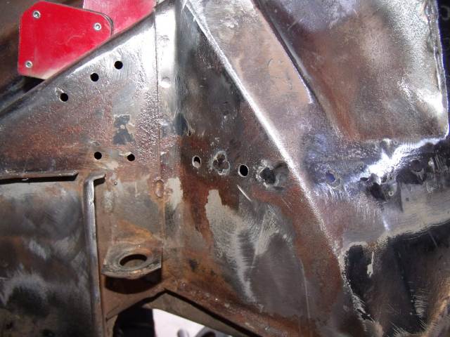 Place the nails again using the small magnets. 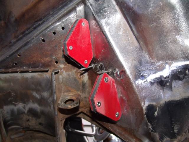 Grind it all off with the disc grinder. 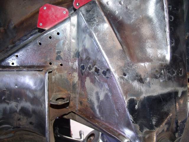 And finish off with the abrasive pad. 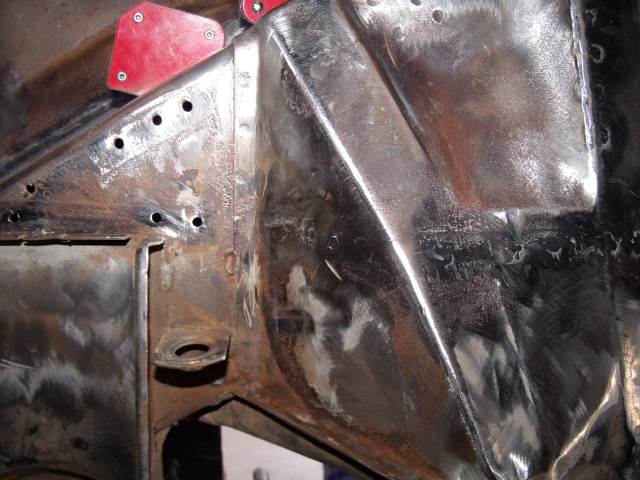 |
|
|
|
| 3d914 |
Jun 22 2012, 05:44 PM
Post
#187
|
|
Senior Member Group: Members Posts: 1,275 Joined: 24-September 03 From: Benson, AZ Member No.: 1,191 Region Association: Southwest Region |
The other technique I use is for butt or plug welds. In these cases I use a small block of copper to act as a backing plate. Here are some holes at the top of the engine bar support. They don't need to be filled, since that upper piece doesn't serve any function now that the shelf is gone - but the results will be cleaner if I fill them.
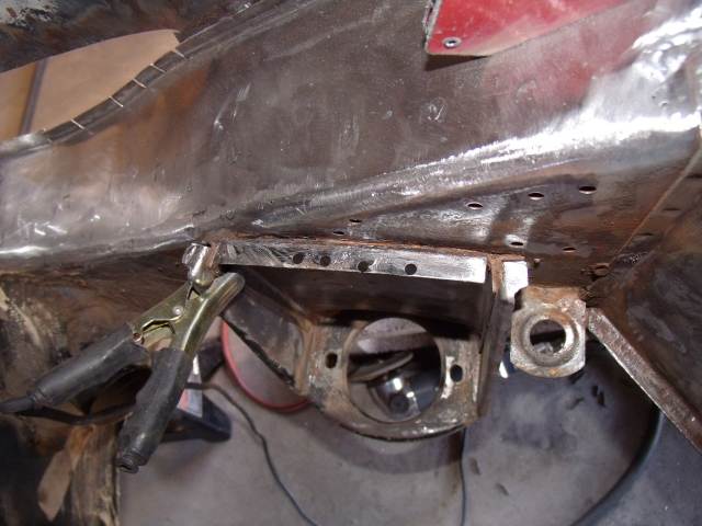 When the back is open & accessible like this I just clamp the copper plate behind the holes to be filled. This one was made from copper tubing I just flattened. 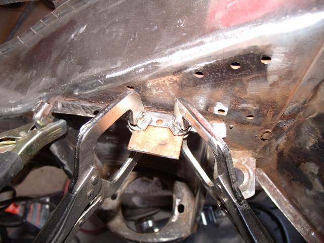 The weld won't stick to the copper, and it helps by absorbing heat. If my welder had more controls this wouldn't be an issue - Low & High is it. 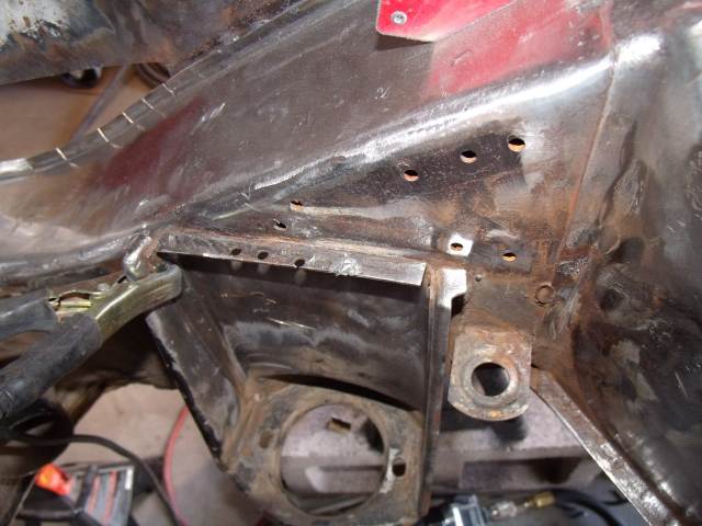 Repeat to weld up the rest. Now their ready for grinding. 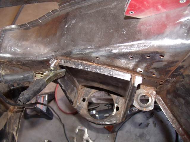 For less accessible places, I made another tool from 1" dia copper tube and a 1"dia wooden dowel. Using about 8" of tubing I slide the tubing over the dowel about 3" and fasten it with a couple of screws. Then just flatten the remaining portion of copper. This really helps when butt-welding pieces, and if necessary I have a helper hold it for me while I weld. All finished up. 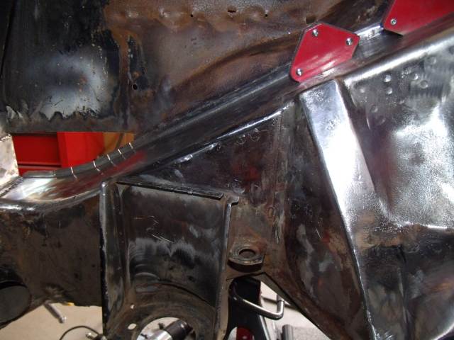 |
|
|
|
| 3d914 |
Jul 2 2012, 06:54 PM
Post
#188
|
|
Senior Member Group: Members Posts: 1,275 Joined: 24-September 03 From: Benson, AZ Member No.: 1,191 Region Association: Southwest Region |
Continue work on the right side of the engine bay. I cleaned up the surface rust near the battery box area and cut out the bad parts. Got my pattern made, but need to cut it out.
 I did get the remaining piece for the hole in the lower-left recut, fit and partially welded. I'll get more pics when both pieces are done - this will wrap up the right side. Can't wait to get this side done. Been too long. And I still have to come back and do reinforcements. (IMG:style_emoticons/default/wacko.gif) 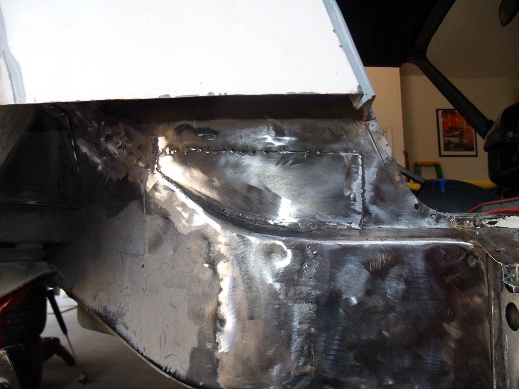 |
|
|
|
| 3d914 |
Jul 7 2012, 07:02 PM
Post
#189
|
|
Senior Member Group: Members Posts: 1,275 Joined: 24-September 03 From: Benson, AZ Member No.: 1,191 Region Association: Southwest Region |
I was working on my son's 914 engine for a couple of days, but need to replace the alternator bracket. So I decided to continue on the SHO wiring for the engine. Had to build two custom cables to connect the Engine harness to the DIS (Distributorless Ignition module). Since the DIS will be mounted to the firewall, I added some mounting plates (upper and lower) on the engine cradle for components like this; fuel pump, ECU, etc.
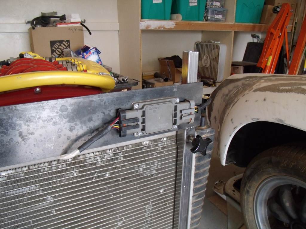 Fuel pump is next. |
|
|
|
| 3d914 |
Jul 11 2012, 06:24 PM
Post
#190
|
|
Senior Member Group: Members Posts: 1,275 Joined: 24-September 03 From: Benson, AZ Member No.: 1,191 Region Association: Southwest Region |
Been a busy week at work so not gettin much time for teener stuff. Did get my PCM (ECU) wiring harness spec'd out and labeled. All items marked in blue will go, but nothings getting cut until the test run is completed.
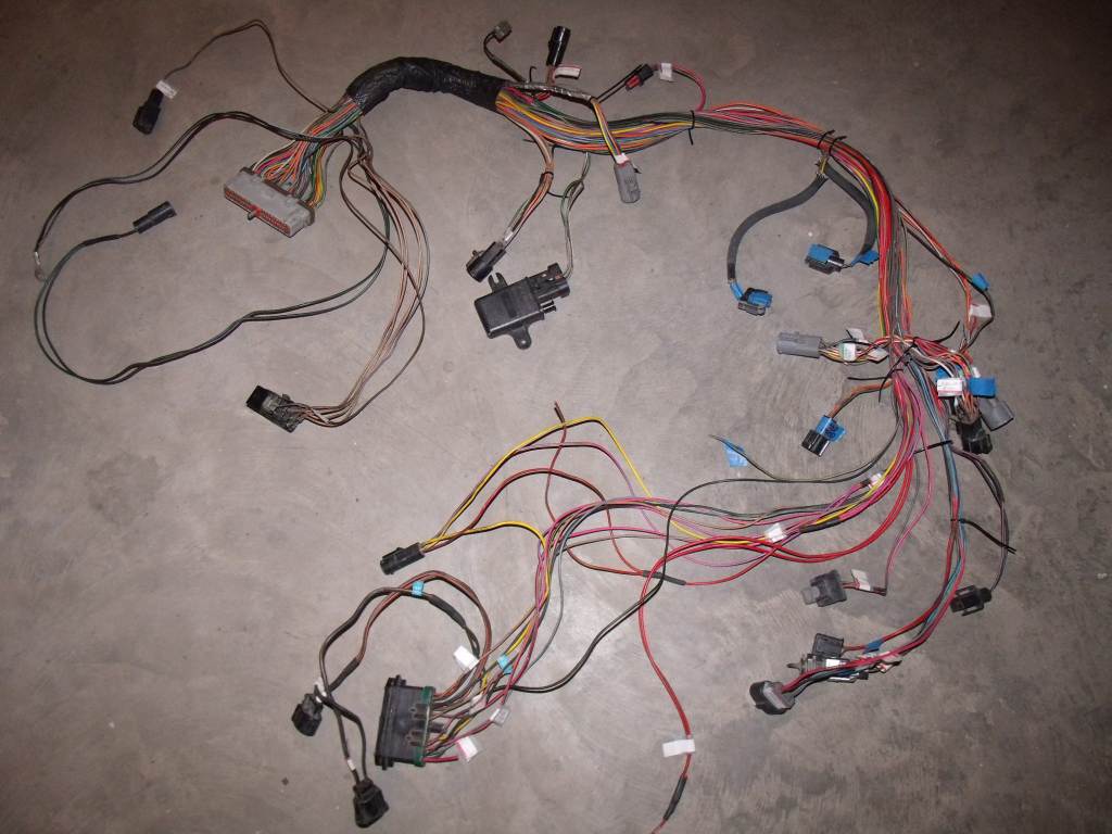 I will also want to complete the test install of the engine before deciding where other engine components will go. So this harness is a rough draft. There are several components like the DIS that get mounted in the engine bay. Big question is locating the battery. I'm planning on using the power distribution box from the SHO and the new style 914 fuse/relay panel. (Thanks Engman) I want the fuse/relay panel somewhere other than under the front dash - so I was thinking - front trunk/drivers side. If the distribution box is up front also, then it makes sense to put the batt up front. If the distribution box is in back (engine bay or trunk) that makes a long run for primary power to the fuse/relay panel - but not that different from stock arrangement. 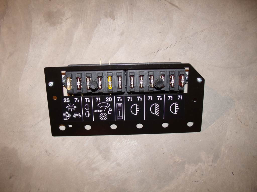 |
|
|
|
| 3d914 |
Jul 14 2012, 07:05 PM
Post
#191
|
|
Senior Member Group: Members Posts: 1,275 Joined: 24-September 03 From: Benson, AZ Member No.: 1,191 Region Association: Southwest Region |
Not much happening today. Finished up some welding and did some running around to get small parts to mount fuel pump temporarily on engine cradle. Also started wiring diagram for fuse/relay panel and how it all ties to the SHO power distribution box.
I'll post some details once I get the diagram done. |
|
|
|
| 3d914 |
Jul 17 2012, 08:20 PM
Post
#192
|
|
Senior Member Group: Members Posts: 1,275 Joined: 24-September 03 From: Benson, AZ Member No.: 1,191 Region Association: Southwest Region |
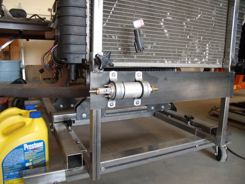
Got to work for a couple hours this evening. The son's 914 now has gear oil in the tranny and I got the fuel pump mounted on the engine cradle.
 |
|
|
|
| 3d914 |
Jul 22 2012, 09:11 PM
Post
#193
|
|
Senior Member Group: Members Posts: 1,275 Joined: 24-September 03 From: Benson, AZ Member No.: 1,191 Region Association: Southwest Region |
Got the fuel lines connected up. One will just run from the the FP into a gas can, and of course the return will run directly into the can.
Also built me a mount for the PCM up front. There are a couple of open loops in the back and I'll use a small bungie cord to hold it. All my small cords disappeared somewhere. 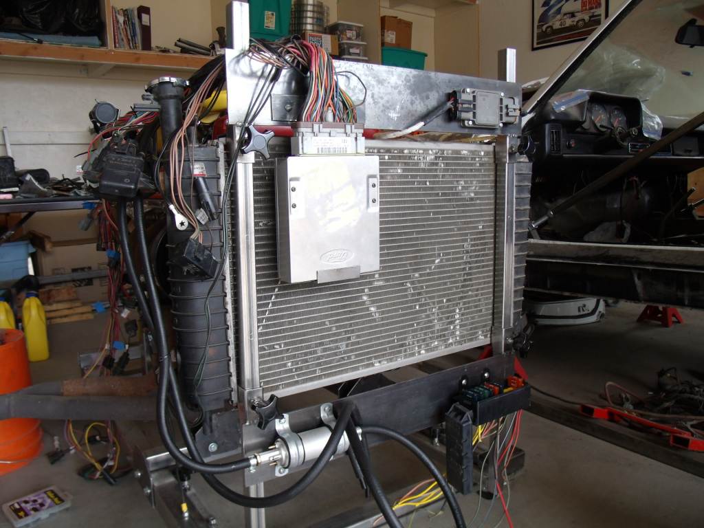 Built some brackets to support the component harness. One also provides a mounting place for the IMRC. I'll need to extend that wiring for its connector, but I'm gonna need to do that for final install anyhoo. Also took care of one of the main grounds in harness - one to the engine block & one to the cradle frame. You can barely see the connector on the PS bracket in the lower-left. I'm thinking I'll do one more bracket that extends back and up (at the left side of pic) so that I can drop straight down for the various relays - since that's where the CCRM connector is at. 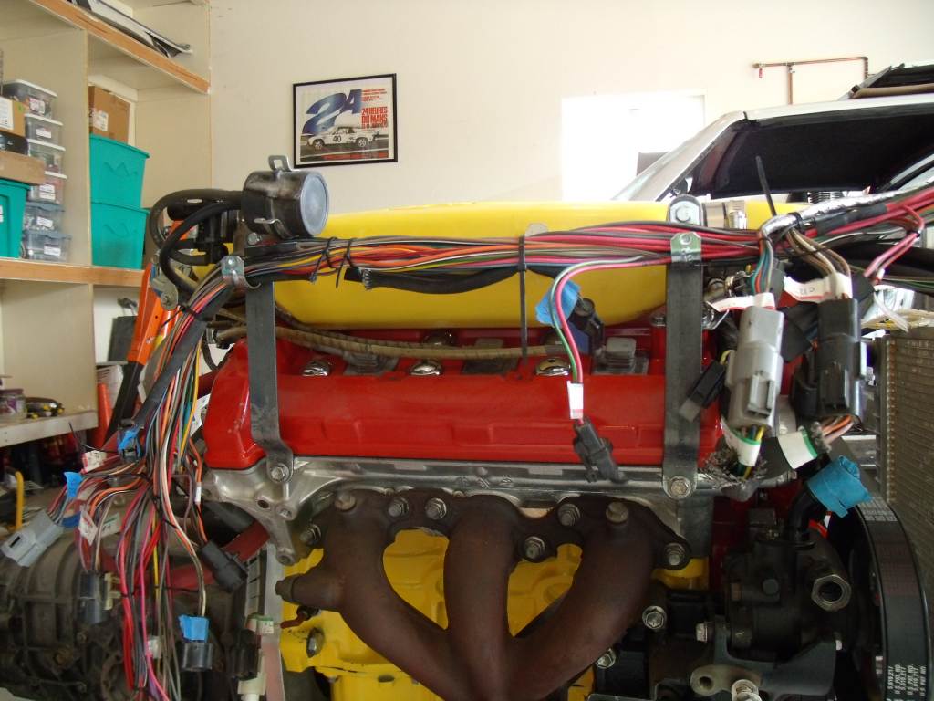 |
|
|
|
| 3d914 |
Jul 22 2012, 09:22 PM
Post
#194
|
|
Senior Member Group: Members Posts: 1,275 Joined: 24-September 03 From: Benson, AZ Member No.: 1,191 Region Association: Southwest Region |
I finished my instrument panel yesterday. It's just tac-welded on back for the moment. I plan to drill holes to mount it to the angle then grind off the welds. Got a SHO tach sourced and need to start locating an ignition switch and some idiot lights for oil pressure, hi & low speed cooling fans. I'll also use two separate switches for BOO & Clutch position.
Almost forgot I mounted the main power distribution box (lower-right, previous post) as well. I'm using nine of the SHO's stock 12 fuses. One 40amp will power the 914's internal fuse/relay panel. Also have plenty of fusing for upgrade head-lights & driving lights. Of course with associated relays. By the time I'm done, I look to have over dozen relays. Now I just have to package them all. 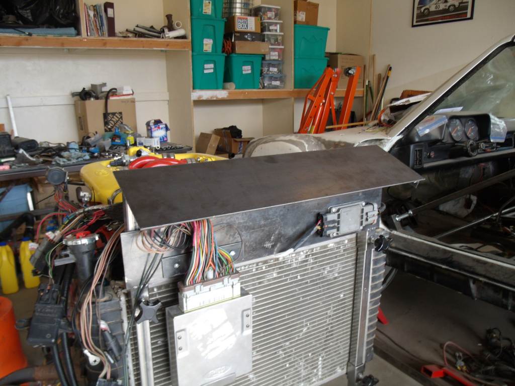 |
|
|
|
| 3d914 |
Jul 29 2012, 07:14 PM
Post
#195
|
|
Senior Member Group: Members Posts: 1,275 Joined: 24-September 03 From: Benson, AZ Member No.: 1,191 Region Association: Southwest Region |
Continuing to get things connected up between the engine harness and the main PCM (ECU) harness. Just using crimp connections for the bench test. I'll sort out routing and final harness once the motor is test fit in the engine bay.
|
|
|
|
| 3d914 |
Sep 12 2012, 08:32 PM
Post
#196
|
|
Senior Member Group: Members Posts: 1,275 Joined: 24-September 03 From: Benson, AZ Member No.: 1,191 Region Association: Southwest Region |
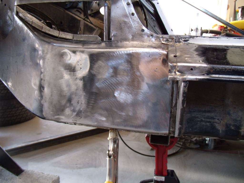
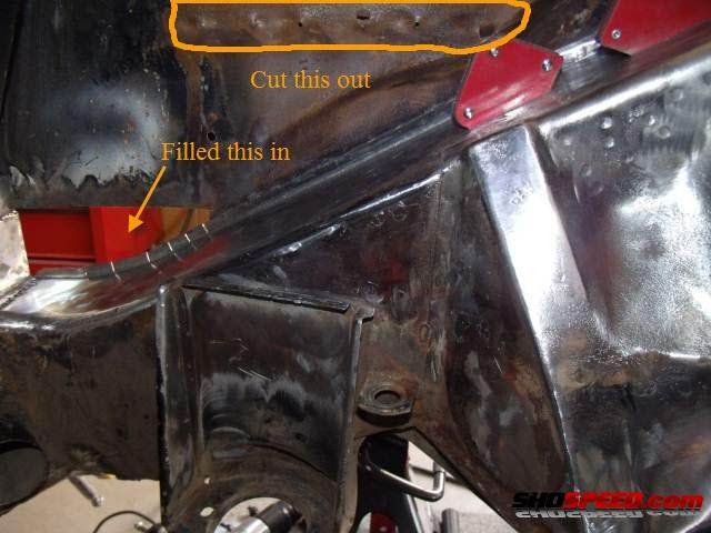
Well finally got the patches on the right side of the engine bay done. Had some time last weekend to fit & spot weld this patch in. Got around to finishing off the welding & grinding tonight.
Piece was a pain in the a$$ to fit because of bends and contour, but a close fit makes the finish welding so much easier. 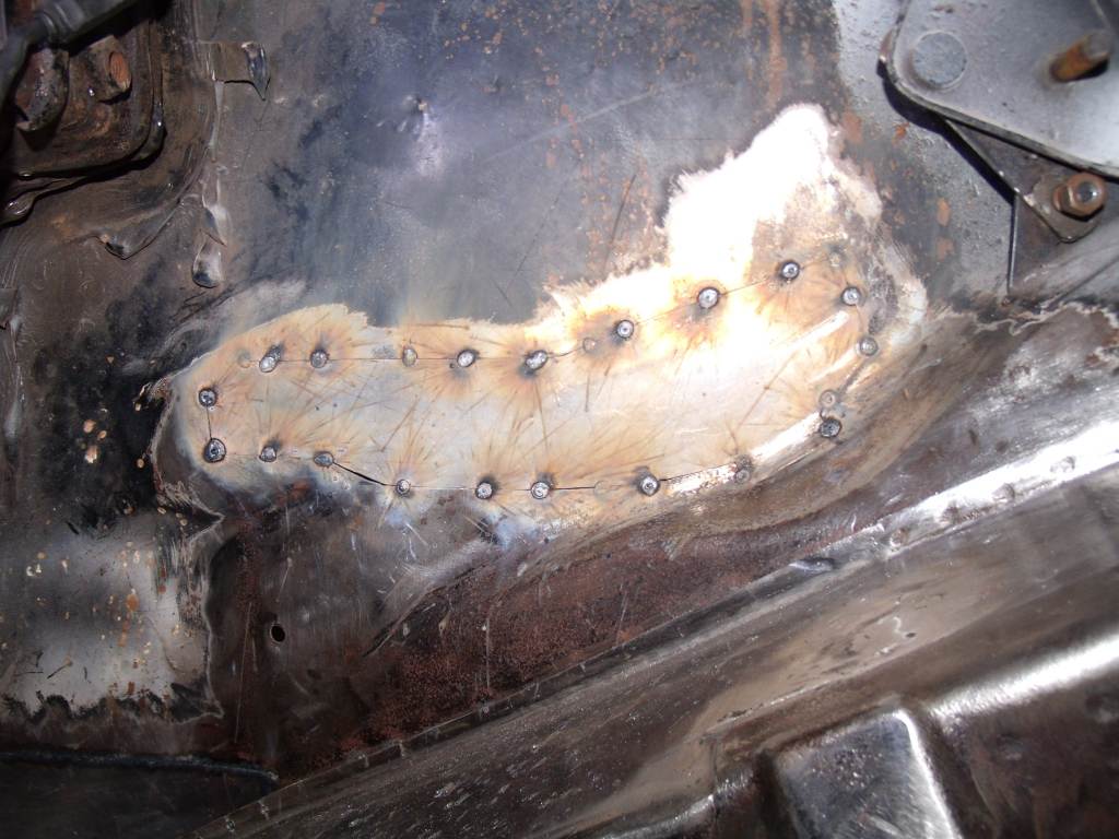 Went from this . . . (IMG:http://www.914world.com/bbs2/uploads/post-1191-1240793385.jpg) to this . . . so I'm happy. 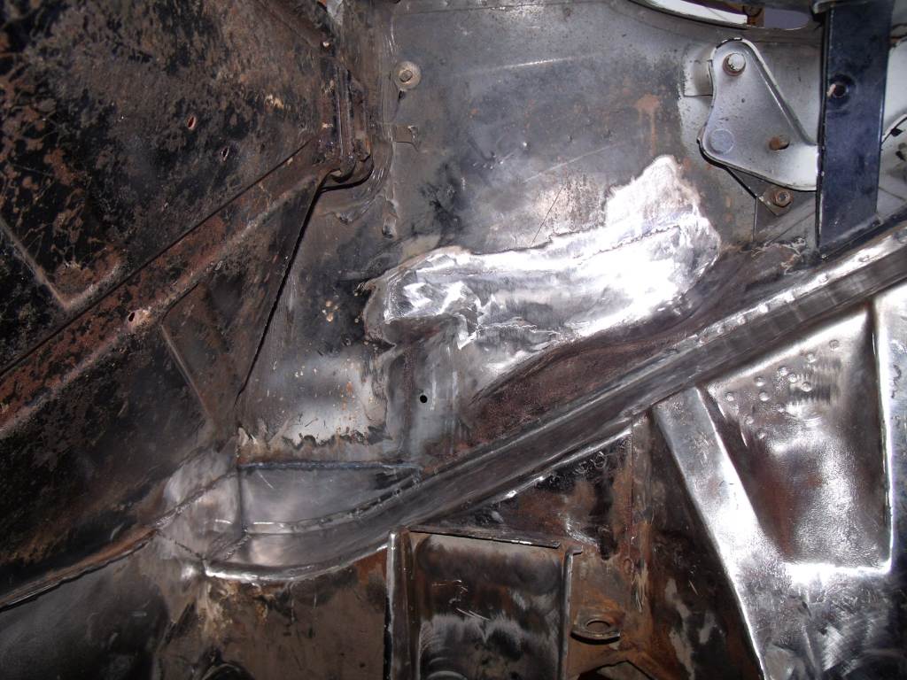 |
|
|
|
| 3d914 |
Sep 15 2012, 01:17 PM
Post
#197
|
|
Senior Member Group: Members Posts: 1,275 Joined: 24-September 03 From: Benson, AZ Member No.: 1,191 Region Association: Southwest Region |
Decided to roll out the 914-SHO and shoot some primer on the repairs made so far. Also gives me a chance to cleanup well, dust the car off, and regroup.
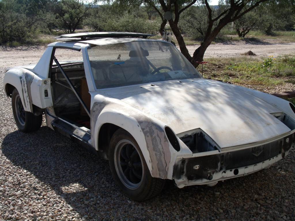 Also decided to do some work on the son's teener. It needed the cobwebs cleaned off. Rolled it into the working spot and will get the engine/tranny installed this weekend. Should have it running by next. 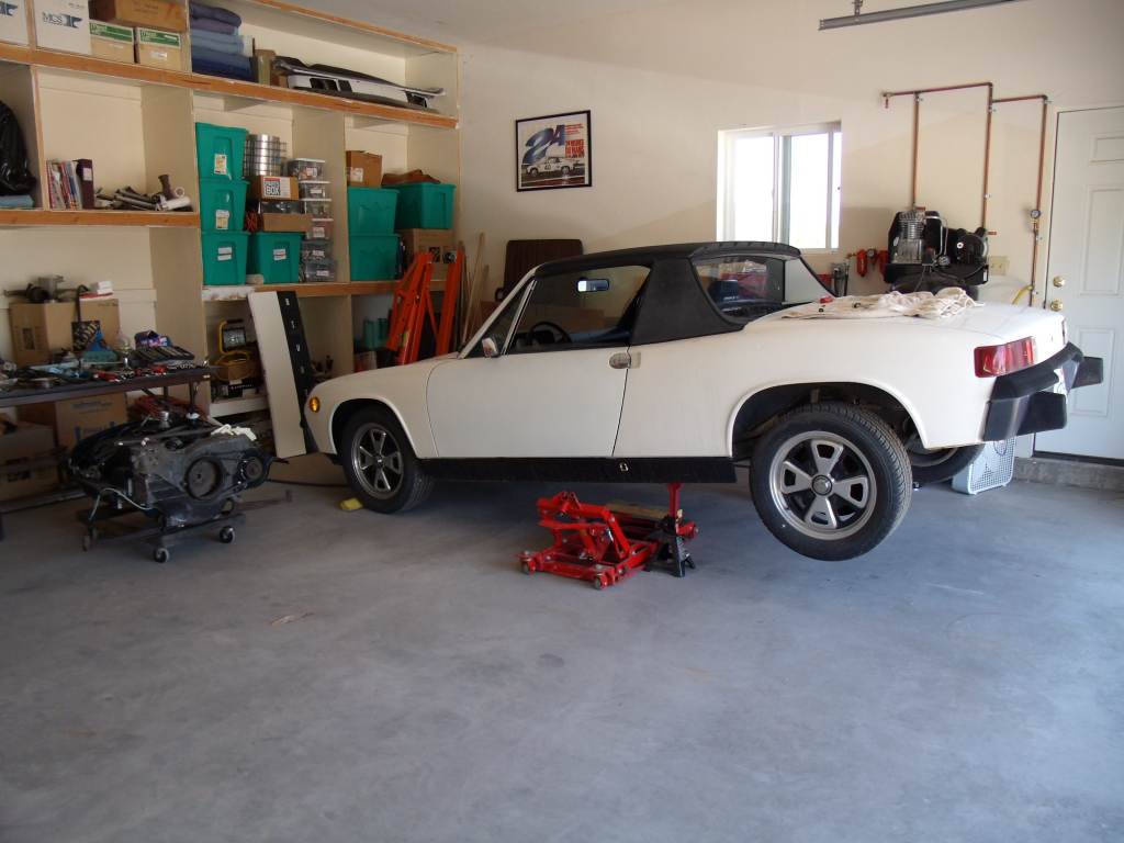 |
|
|
|
| 3d914 |
Sep 23 2012, 07:00 PM
Post
#198
|
|
Senior Member Group: Members Posts: 1,275 Joined: 24-September 03 From: Benson, AZ Member No.: 1,191 Region Association: Southwest Region |
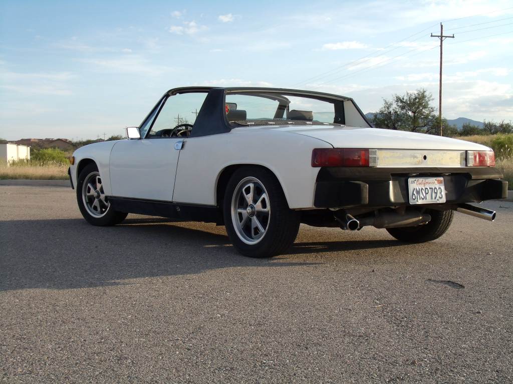
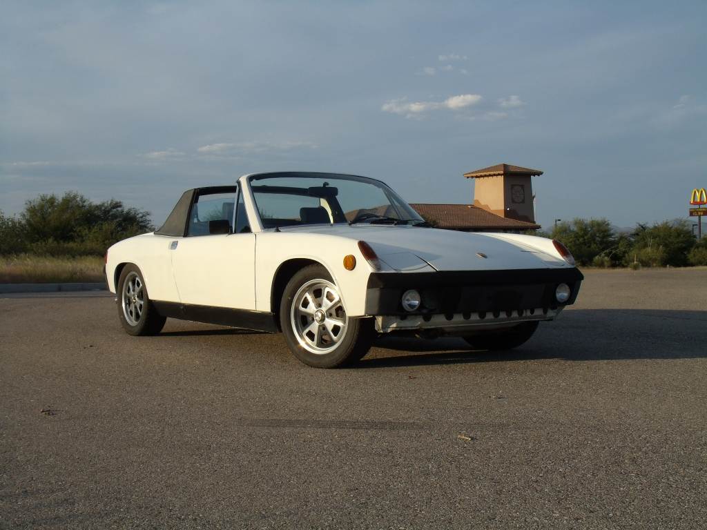
Got the son's teener runnin. Took it out for a short drive and some pics. Sure miss the low ride of a 914.
  |
|
|
|
| 3d914 |
Sep 30 2012, 09:39 PM
Post
#199
|
|
Senior Member Group: Members Posts: 1,275 Joined: 24-September 03 From: Benson, AZ Member No.: 1,191 Region Association: Southwest Region |
Nothing special this weekend. I had a little time this weekend to continue working on wiring for the bench test. Still waiting to get the switches and misc gauges I need. Picked up a nice instrument cluster for the SHO. I'm actually going to see if I can use more of the cluster. It's a very close fit to the stock 914.
I've decided not to tear it apart just for the tach, but I'll find a way to mount the whole cluster on the test stand and connect to just the tach. Maybe use a couple of idiot lights and the CEL light. |
|
|
|
| 3d914 |
Nov 5 2012, 01:31 PM
Post
#200
|
|
Senior Member Group: Members Posts: 1,275 Joined: 24-September 03 From: Benson, AZ Member No.: 1,191 Region Association: Southwest Region |
Spent the last couple of weekends finishing up the wiring. Got everything hooked up except the battery positive, related fusable links, and the ignition switch. Been a challenge finding a multi-deck, 3-position ignition switch to mount on the stand.
Right side 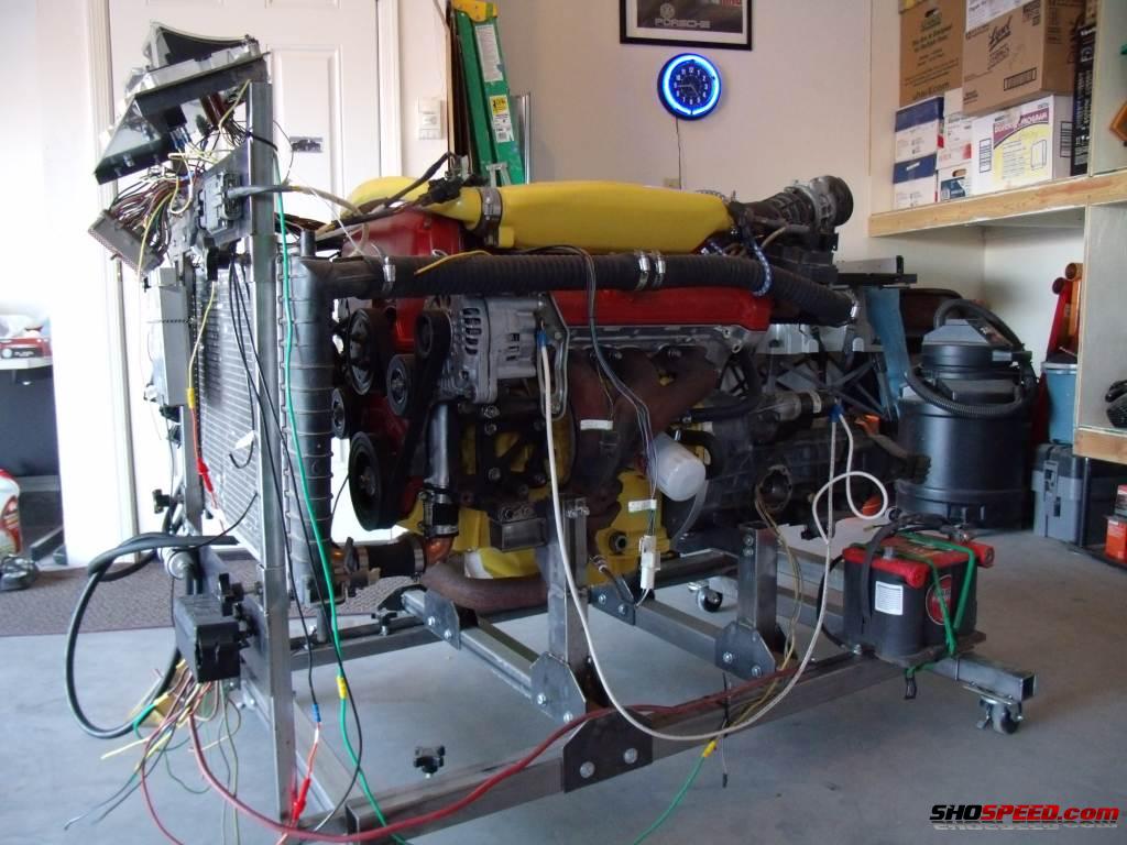 Left side 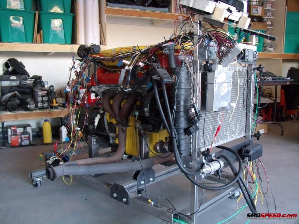 Decided to use the SHO instrument panel as-is which saved worrying about other gauges/senders. Looks funny, but it will work fine. 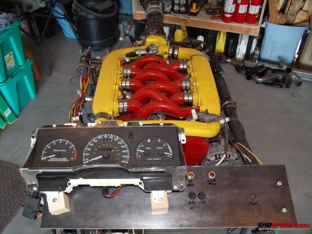 |
|
|
|
|
1 User(s) are reading this topic (1 Guests and 0 Anonymous Users)
0 Members:

|
Lo-Fi Version | Time is now: 24th June 2026 - 04:30 PM |
Invision Power Board
v9.1.4 © 2026 IPS, Inc.