|
|
|
Porsche, and the Porsche crest are registered trademarks of Dr. Ing. h.c. F. Porsche AG.
This site is not affiliated with Porsche in any way. Its only purpose is to provide an online forum for car enthusiasts. All other trademarks are property of their respective owners. |
|
|

  |

| 3d914 |
 Dec 28 2013, 02:51 PM Dec 28 2013, 02:51 PM
Post
#321
|
|
Senior Member  Group: Members Posts: 1,275 Joined: 24-September 03 From: Benson, AZ Member No.: 1,191 Region Association: Southwest Region |
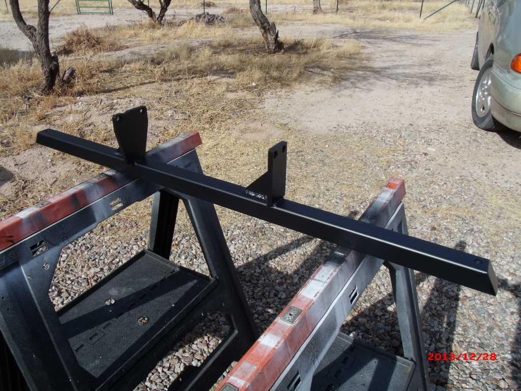
Engine bar is primered/painted and ready for another test fit so I can decide what option to use on the tranny mounts.
 |
   |

 
|
| 3d914 |
Dec 28 2013, 06:14 PM
Post
#322
|
|
Senior Member Group: Members Posts: 1,275 Joined: 24-September 03 From: Benson, AZ Member No.: 1,191 Region Association: Southwest Region |
OK, spent the rest of the day getting the tranny mounting squared away. By using a level on the engine bar I was able to adjust the spacing between the stock tranny mounts and the mounting flange on the body. It worked out to be 3/4 inch.
So off to Ace to find all the appropriate hardware. Got the 8mm bolts with some extra length and found some steel spacers that fit nicely. 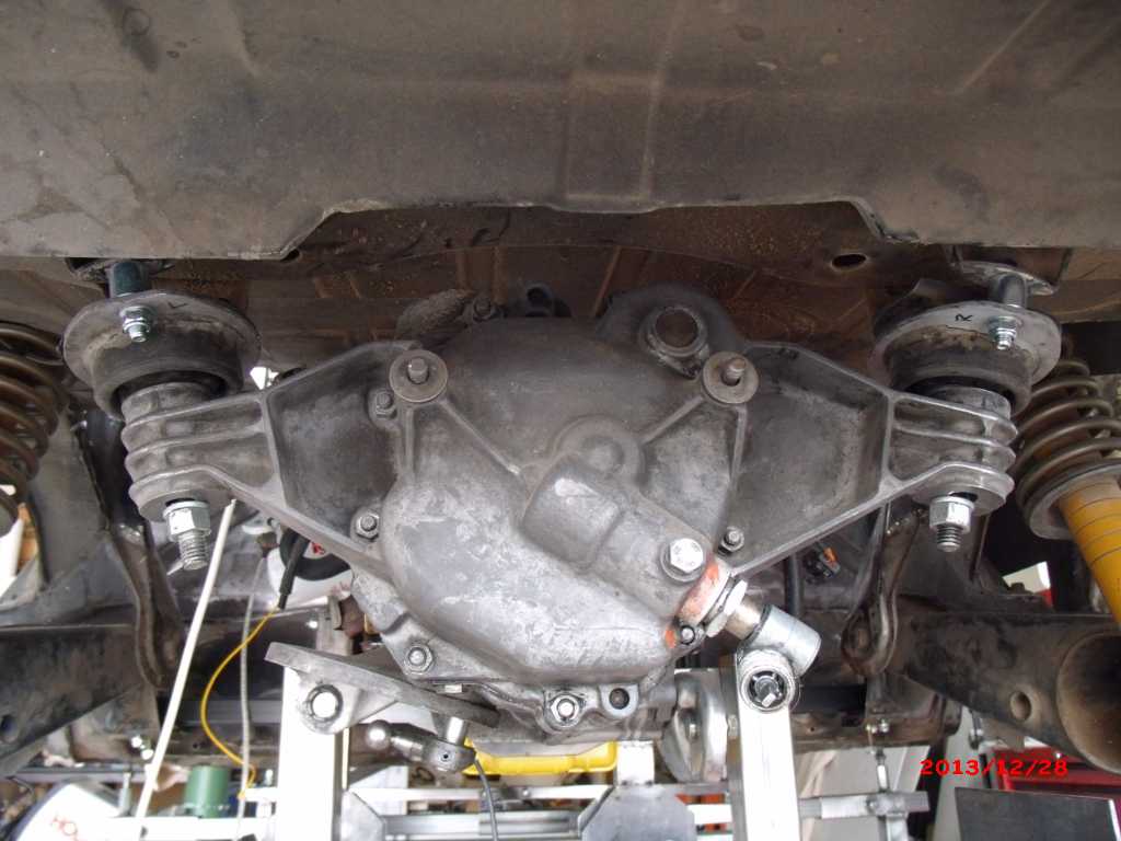 Also added some large washers on the 12mm bolts (not shown in pic) since the positioning is a little forward of stock. Still sitting squarely on the flange of the arm though so I think this will work fine. 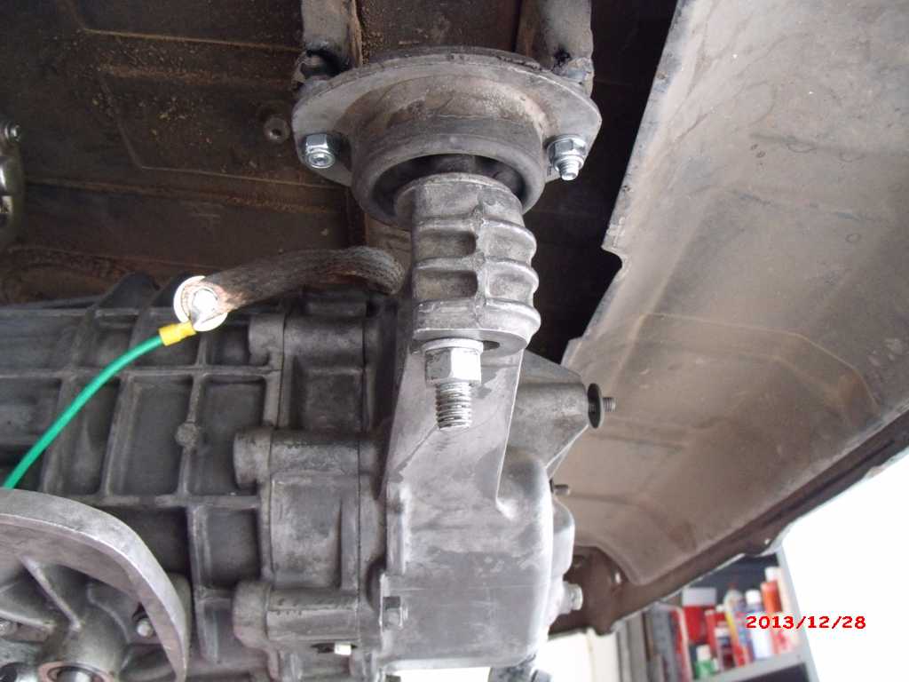 So engine is sitting level and I have plenty of space (approx 1 inch) between the front firewall and the surge tank. 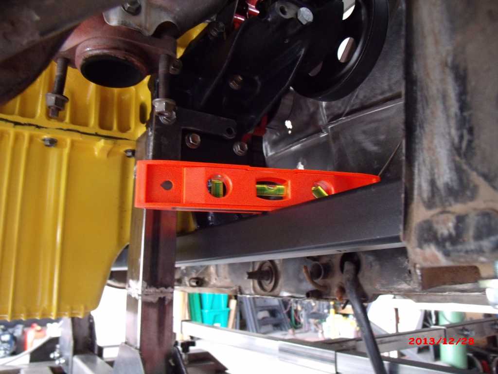 |
|
|
|
| 3d914 |
Dec 29 2013, 02:40 PM
Post
#323
|
|
Senior Member Group: Members Posts: 1,275 Joined: 24-September 03 From: Benson, AZ Member No.: 1,191 Region Association: Southwest Region |
Hoo-Raa! Another milestone. (IMG:style_emoticons/default/piratenanner.gif) The engine cradle is down and the motor/tranny is mounted in the body! (IMG:style_emoticons/default/piratenanner.gif)
OK, so the last two positional checks are for the stock shift bar and my exhaust mockup. The shift bar fits as expected and clears the engine bar, the oil pan, the adapter plate, and the exhaust. Even though the exhaust appears to touch - my mockup is oversized and the radius' are too sharp. I had to remove the ATX manifold on the left (front) side because I'm going to use the MTX version on that side since it fits better. Wasn't that bad getting the manifold off. Lots of space - more probably than in the stock SHO. 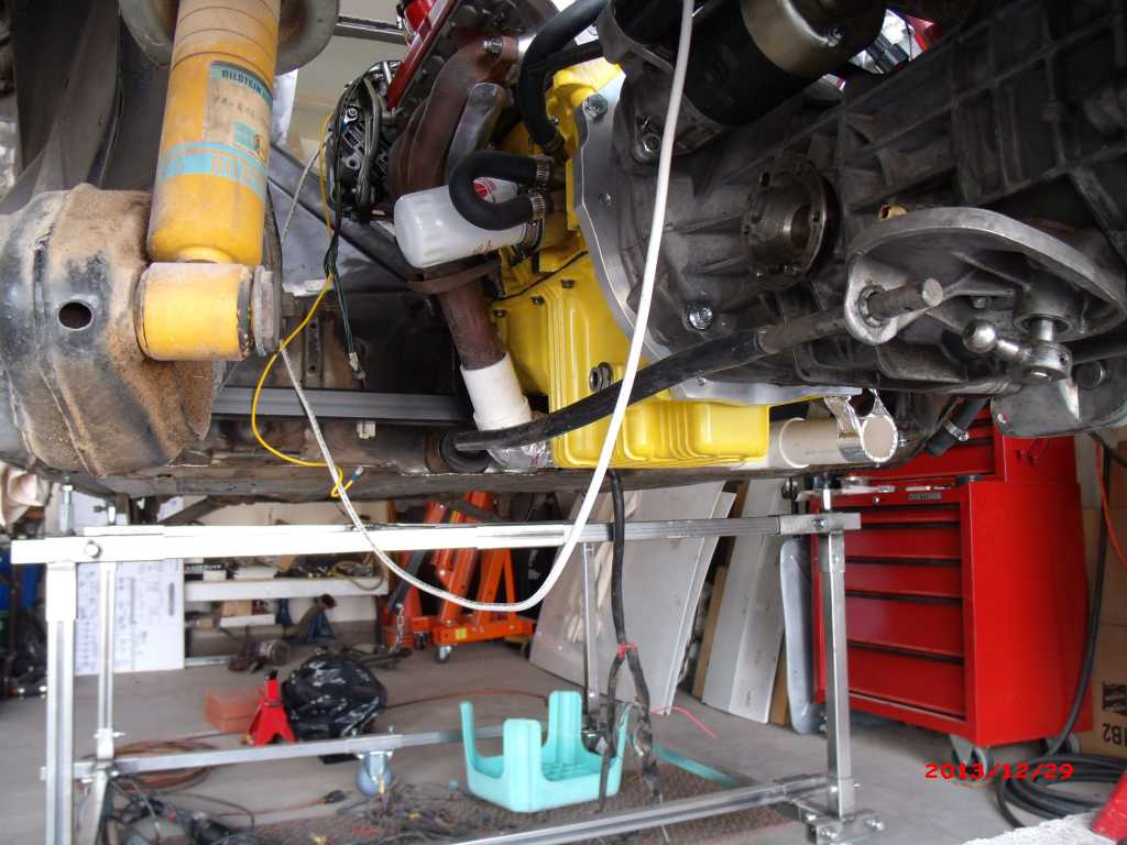 The right (back) side manifold off the ATX stays since it drops straight down - and this is where I'm going to blend the 2 inch pipes into a single 2.5 inch pipe. Except my blend will be a vertical one instead of horizontal. Looks like its time to go mandrel shopping so I can fab the exhaust. 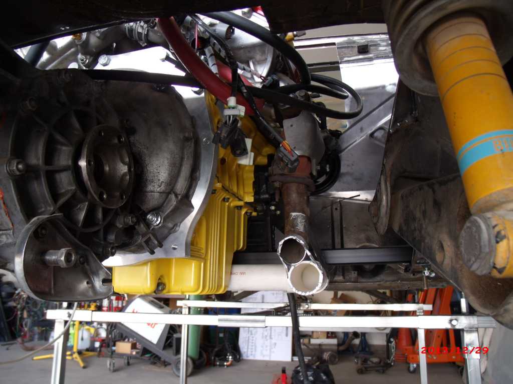 |
|
|
|
| 3d914 |
Dec 29 2013, 04:43 PM
Post
#324
|
|
Senior Member Group: Members Posts: 1,275 Joined: 24-September 03 From: Benson, AZ Member No.: 1,191 Region Association: Southwest Region |
Wanted to see how the engine lid would fit so I cut up the one that came with the car to illustrate where I'm going with this. You can see there is plenty of clearance with the cross-support removed. I'll add the cross piece back after I modify how it mounts so the cross-section extends up into the cavity instead of down into the engine bay.
I'll be using this lid & the trunk to mock up my final parts. I already have a new engine lid that will be customized and covered with grill all over like the GT/6 version. But the middle section at the back (where its cut out) will have its shape/height match the front section & then I'll transition the two side pieces in. 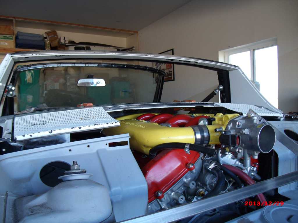 |
|
|
|
| 3d914 |
Jan 1 2014, 06:20 PM
Post
#325
|
|
Senior Member Group: Members Posts: 1,275 Joined: 24-September 03 From: Benson, AZ Member No.: 1,191 Region Association: Southwest Region |
Took a few hours before dinner to work on the trunk and air filter location. The air filter will have a custom box built to hold the 8-1/2 x 11 inch air filter. The box will need to be deep enough to feed the 4-inch diameter supply tube to the MAF sensor.
I can adjust the position of the air filter/box as needed based on how I decide to size/locate the NACA duct(s) that will feed the air through the trunk lid. 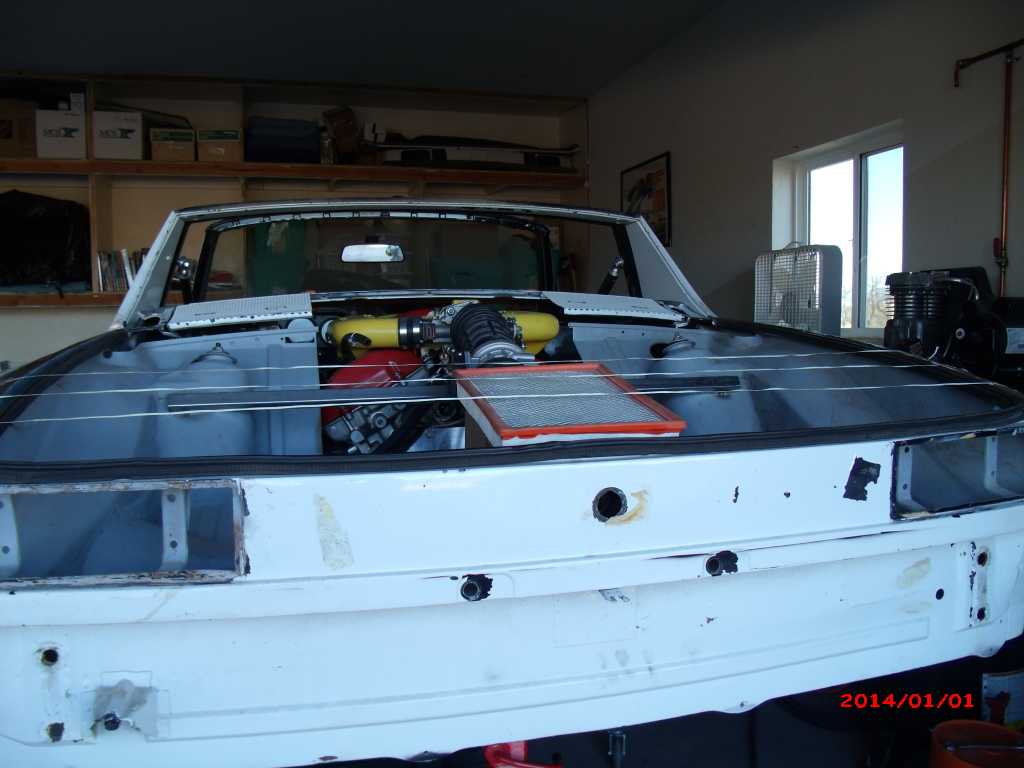 I want the filter to sit as high as possible so that there should be some room left under the filter box, and it will require some legs to elevate it. 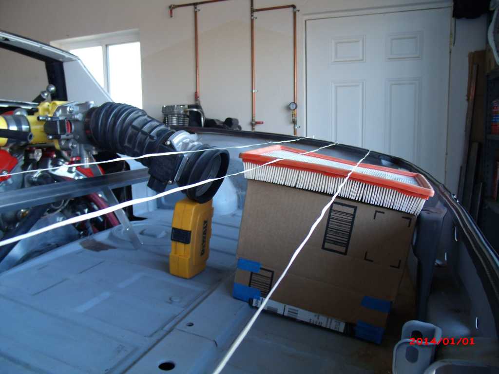 Of course there are some obstructions on the underside of the trunk lid I'll have to adjust for also. 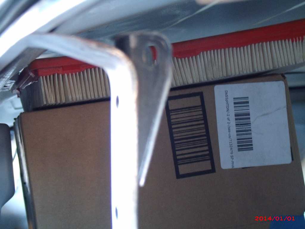 |
|
|
|
| 3d914 |
Jan 1 2014, 06:23 PM
Post
#326
|
|
Senior Member Group: Members Posts: 1,275 Joined: 24-September 03 From: Benson, AZ Member No.: 1,191 Region Association: Southwest Region |
Here's what it looks like with the trunk lid on. It's been modified to fit around the surge tank and throttle body. Cutting through the support channels weakened it of course, so I'm planning to scavenge support channels from this trunk & another used trunk lid and add them to my final lid.
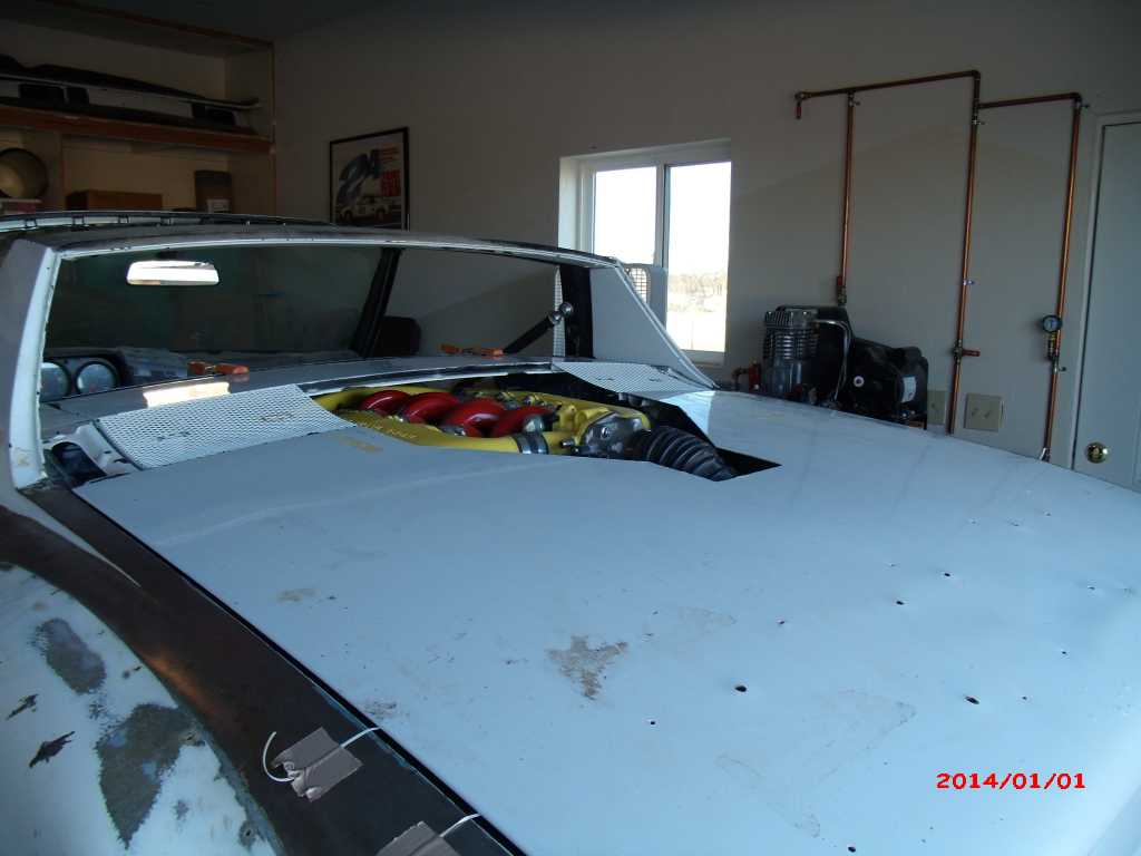 To cover the surge tank & intake I'll continue the slope and curvature of the forward part of the engine lid, down along the trunk to the stopping point. The sides will be tapered in & upward toward the centerline at 22.5 deg. This will match the angle on the 914's L & R sail panels. 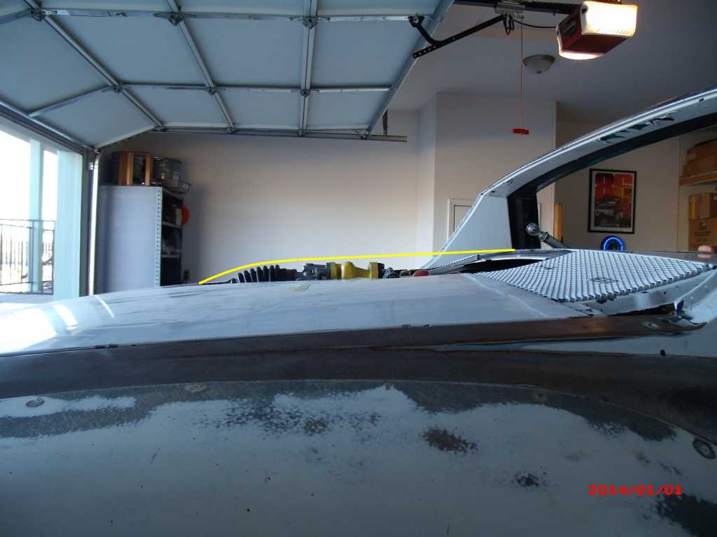 |
|
|
|
| Krieger |
Jan 1 2014, 06:52 PM
Post
#327
|
|
Advanced Member Group: Members Posts: 4,863 Joined: 24-May 04 From: Santa Rosa CA Member No.: 2,104 Region Association: None |
Gerard you will have to cut out the rear firewall section before you put the angle iron in. If you look carefully you will see I only cut the forward section on mine. I think since you already cut through the entire firewall it wont make a difference if you remove the remnants. I was able to preserve some usage of the rear trunk.
|
|
|
|
| 3d914 |
Jan 2 2014, 12:05 PM
Post
#328
|
|
Senior Member Group: Members Posts: 1,275 Joined: 24-September 03 From: Benson, AZ Member No.: 1,191 Region Association: Southwest Region |
QUOTE(Krieger @ Jan 1 2014, 05:52 PM)  Gerard you will have to cut out the rear firewall section before you put the angle iron in. If you look carefully you will see I only cut the forward section on mine. I think since you already cut through the entire firewall it wont make a difference if you remove the remnants. I was able to preserve some usage of the rear trunk. Andy, thanks for the tip. I've added this to my list of reinforcements planned for the higher torque motor. Decided to try a different path on the rear-hinged trunk. Taking an idea from the mini cooper trunk hinge, I saw how I could get the offset I needed when rotating so that it clears the vertical mating surfaces along the back panel. But I also wanted to integrate the engine lid with the trunk so that when the one opens it pulls the engine lid with it. The hinges between the trunk & engine lid will prevent rotation of more then 80-90 degrees. This is so that the engine lid will be in the correct position when closing to land its rollers on a small track added to those little extensions on the body (each side of the engine lid). The front of the engine lid will have a couple of pins to lock it into the main firewall. 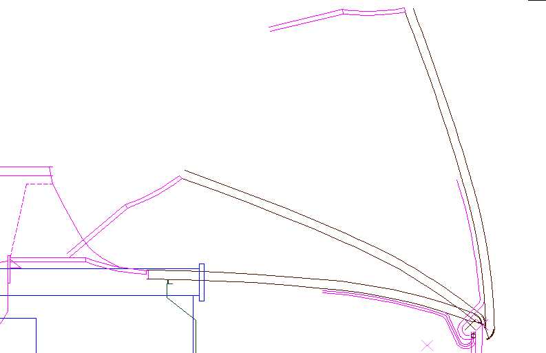 |
|
|
|
| 3d914 |
Jan 4 2014, 10:12 PM
Post
#329
|
|
Senior Member Group: Members Posts: 1,275 Joined: 24-September 03 From: Benson, AZ Member No.: 1,191 Region Association: Southwest Region |
Spent some time trying to finalize how I'm doing the air intake. Here are the primary requirements/constraints:
Searching the internet turned up many options for for the ducts - from ABS plastic to FG or CF. Decided to go with the ABS since I can heat it slightly if necessary to conform to the lids curvature. Many of the ducts use 3" outlets to connect hoses to. Unfortunately this restricts the intake area to a mere 7 sq.in or less. I'd like to have double that - so maybe two NACA ducts - OK. Here's my rough sketch on how it all would fit together. Not shown is a sheet metal support frame to support the air box and give me little bit of storage under it. Thoughts - feedback? 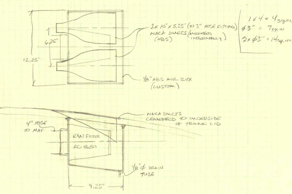 |
|
|
|
| 3d914 |
Jan 11 2014, 09:50 PM
Post
#330
|
|
Senior Member Group: Members Posts: 1,275 Joined: 24-September 03 From: Benson, AZ Member No.: 1,191 Region Association: Southwest Region |
Well spent the day mostly indoors on the computer. After I pulled the necessary dimensions, I needed to bring my air box design into CAD and make sure things fit. Good thing I did. The tight angle of the MAF and the size of the K&N filter I chose didn't work. I also mis-measured the MAF intake size. I was going by the coupling that was on there - which isn't needed in my case - so that reduced the needed hose ID down to 3.5 in.
Because space is tight I don't really want to have a straight sleeve between the filter's flange and the elbow to the MAF. So I decided to size the ID of the filter to the OD of the elbow. The silicone elbows are rigid enough it shouldn't capsize. I got lucky and the filter I found has an offset flange - so that works to my advantage also. The only thing that's not ideal is the amount of space between the end of the NACA duct and the back wall of the air box. I wanted to keep the box under 12 inches since it's easier to find material in that width. Box width is at 10 inches now, so I may decide to use the rest of the space - but I'll wait until I have the material in hand and can mock it up first. Here's how it looks so far: 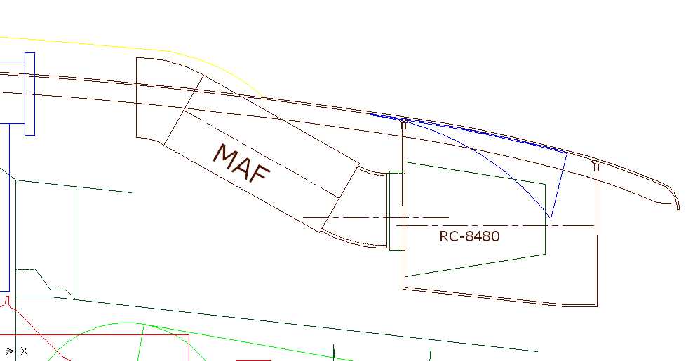 |
|
|
|
| 3d914 |
Jan 26 2014, 04:00 PM
Post
#331
|
|
Senior Member Group: Members Posts: 1,275 Joined: 24-September 03 From: Benson, AZ Member No.: 1,191 Region Association: Southwest Region |
Got some time in this weekend - but not a lot. Spent yesterday working on the welder my neighbor let me borrow- Hobart 170. The shielding gas wasn't getting out to the weld - so I checked all the hoses to verify nothing was clogged. Turned out to be the gauge - it was misreading. Now to find a 10-50 CFH dial gauge for argon. Also tested the wire feed. It has infinitely adjustable feed rate, but when I had it on the first setting it was too fast. After testing there was only 20-IPM difference between setting 1 and setting 10. Up to neighbor whether to get it serviced or not. I'm off to buy my own. Gonna go with the Longevity 140 since it has optional spooling gun for aluminum.
|
|
|
|
| 3d914 |
Jan 26 2014, 04:09 PM
Post
#332
|
|
Senior Member Group: Members Posts: 1,275 Joined: 24-September 03 From: Benson, AZ Member No.: 1,191 Region Association: Southwest Region |
Spent today doing metal trimming for the two firewall sections. Its been very time consuming to get things to fit right on all four sides + curvatures. So I decided to fit three sides and do the lower part as a flat face instead of the curved I was attempting. Just don't have the tools to do the job properly.
Even fitting three sides takes a lot of fit & trim, fit & trim again, fit & trim again, . . . But finally got both side ready for tack welding. The lower edge trimming will be done once they are tacked on, since the cut is related to the main firewall. Right side 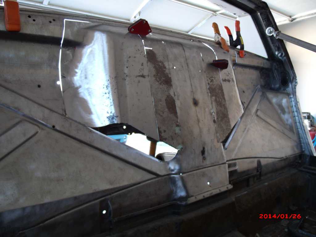 Left side 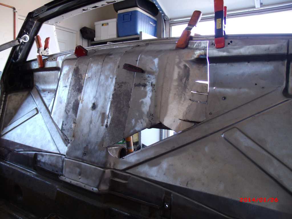 Back 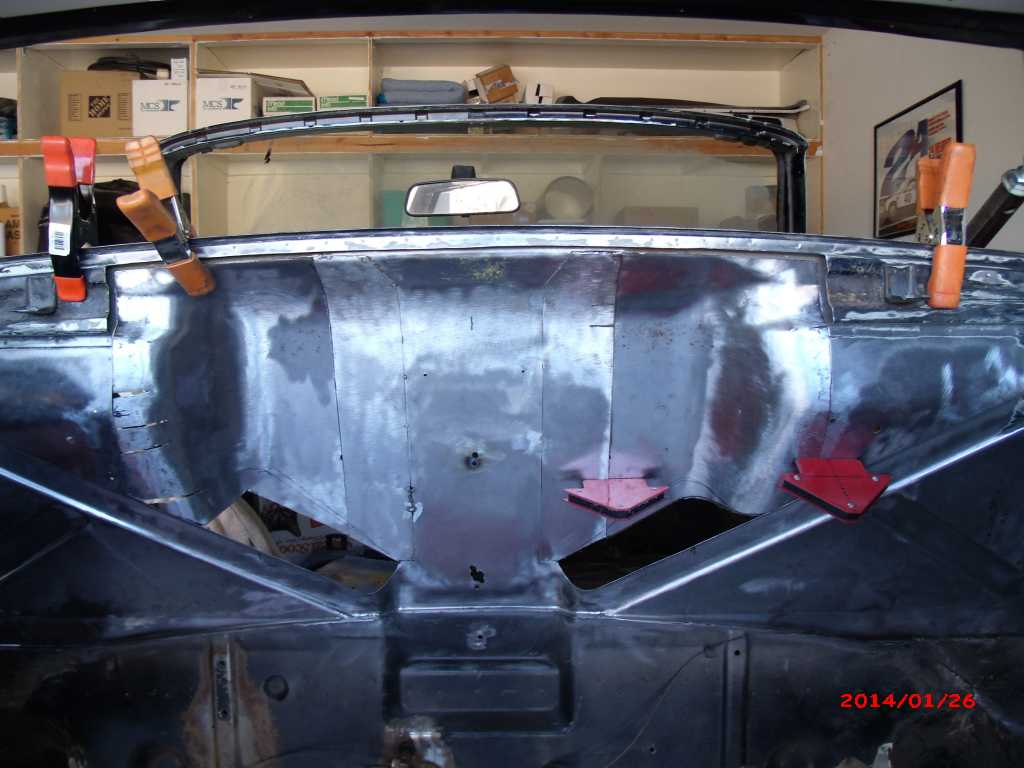 |
|
|
|
| 3d914 |
Feb 1 2014, 05:24 PM
Post
#333
|
|
Senior Member Group: Members Posts: 1,275 Joined: 24-September 03 From: Benson, AZ Member No.: 1,191 Region Association: Southwest Region |
New welder came in Friday afternoon - so spent some time assembling and setting it up. Got to do some testing today. The Longevity 140 I went with has 25-140amp range so I can get the arc volts down to work with this thin sheet metal. The thinnest stuff is 20 gauge, but some areas are thicker 18 & 16 gauge.
I tried flux core wire first. It worked better than my other welder - fewer blow-thrus, but I still couldn't get the amp volts below 55 - that wire just doesn't work well below that point. Then decided to try the .023 steel wire and use gas. This helped a lot. I was able to get the arc volts down near 35 - and with the C25 gas was able to do more than just spot welds. It even worked well to fill previous blow-thrus. There's a little more material build up than with the flux core, but I'll keep tweeking the settings. Still reasonable happy with the results. 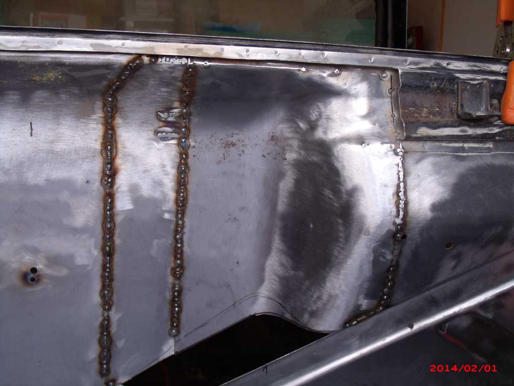 |
|
|
|
| mgp4591 |
Feb 1 2014, 08:07 PM
Post
#334
|
|
914 Guru Group: Members Posts: 5,957 Joined: 1-August 12 From: Salt Lake City Ut Member No.: 14,748 Region Association: Intermountain Region |
That's a TON of work you've done fitting that engine in there- May the Forsche be with you! (IMG:style_emoticons/default/welder.gif)
|
|
|
|
| 3d914 |
Feb 2 2014, 05:10 PM
Post
#335
|
|
Senior Member Group: Members Posts: 1,275 Joined: 24-September 03 From: Benson, AZ Member No.: 1,191 Region Association: Southwest Region |
QUOTE(mgp4591 @ Feb 1 2014, 07:07 PM) That's a TON of work you've done fitting that engine in there- May the Forsche be with you! (IMG:style_emoticons/default/welder.gif) Thanks. |
|
|
|
| 3d914 |
Feb 2 2014, 05:12 PM
Post
#336
|
|
Senior Member Group: Members Posts: 1,275 Joined: 24-September 03 From: Benson, AZ Member No.: 1,191 Region Association: Southwest Region |
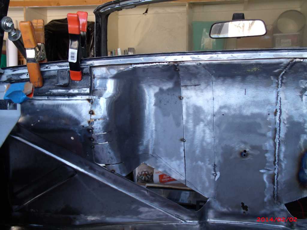
Had to spend some time today doing additional fitting on the left side, but did manage to get it tacked in. I'll also have to add some fill-in pieces and cleanup up some of the curves, but its well on its way. Going to try and avoid any warpage if possible.
 |
|
|
|
| 3d914 |
Feb 10 2014, 08:43 PM
Post
#337
|
|
Senior Member Group: Members Posts: 1,275 Joined: 24-September 03 From: Benson, AZ Member No.: 1,191 Region Association: Southwest Region |
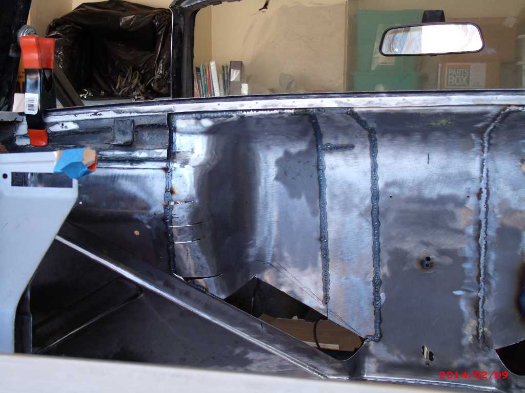
Busy weekend so not a lot of time on the project. Did get the left side of firewall welded up, but still have the fill-in pieces to do. Felt like crap so only worked a couple of hours.
 |
|
|
|
| Cairo94507 |
Feb 11 2014, 07:33 AM
Post
#338
|
|
Michael Group: Members Posts: 10,677 Joined: 1-November 08 From: Auburn, CA Member No.: 9,712 Region Association: Northern California |
Wow you are making nice progress.
|
|
|
|
| 3d914 |
Feb 11 2014, 06:48 PM
Post
#339
|
|
Senior Member Group: Members Posts: 1,275 Joined: 24-September 03 From: Benson, AZ Member No.: 1,191 Region Association: Southwest Region |
QUOTE(Cairo94507 @ Feb 11 2014, 06:33 AM) Wow you are making nice progress. Thanks. Its been slow with just a flux-core welder. Now that I have a good welder I think I can make even better progress. Got soo much welding yet to do:
|
|
|
|
| FourBlades |
Feb 11 2014, 07:31 PM
Post
#340
|
|
From Wreck to Rockin Group: Members Posts: 2,056 Joined: 3-December 07 From: Brevard, FL Member No.: 8,414 Region Association: South East States |
Great metal work and welding. (IMG:style_emoticons/default/welder.gif) The 914 is going to fly with this motor in it! Looking forward to hearing it scream. (IMG:style_emoticons/default/drooley.gif) John |
|
|
|
|
2 User(s) are reading this topic (2 Guests and 0 Anonymous Users)
0 Members:

|
Lo-Fi Version | Time is now: 22nd June 2026 - 09:14 AM |
Invision Power Board
v9.1.4 © 2026 IPS, Inc.