|
|
|
Porsche, and the Porsche crest are registered trademarks of Dr. Ing. h.c. F. Porsche AG.
This site is not affiliated with Porsche in any way. Its only purpose is to provide an online forum for car enthusiasts. All other trademarks are property of their respective owners. |
|
|


| 3d914 |
 Mar 30 2008, 06:59 PM Mar 30 2008, 06:59 PM
Post
#41
|
|
Senior Member  Group: Members Posts: 1,275 Joined: 24-September 03 From: Benson, AZ Member No.: 1,191 Region Association: Southwest Region |
OK here goes . . .
I sold my beautiful Ravenna 914/2.0 so I could develop a custom 914 in good conscience. The sweet Ravenna was to stock to cut up and customize, & an admiring buyer wanted to return her to full stock - so it seemed like the perfect match. Now I've found a 74 1.7 that someone has already led down the path of the Dark Side (as the puritans see it), and I'll simply take it the rest of the way. Just as a warning - this is not meant to be a factory GT look alike or anything close. I want to incorporate some of my own ideas and those I like that others have done. In fact at this point its not even going to be a Porsche six. My initial intent is to go with the Ford 3.0L SHO. Plans may change when I get to that point, but that's where I'm headed. It seems reasonable to start with Before pics, so heres a couple of the car before I started any dismantling: 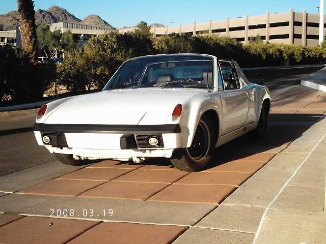 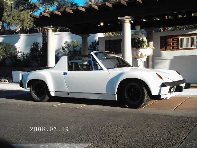 |
   |

 
|
Posts in this topic
3d914 3D914s 914-6 SHO 3.2L v6 Mar 30 2008, 06:59 PM 3d914 OK now we get down to the fun stuff - stripping... Mar 30 2008, 07:04 PM 3d914 Next I wanted to clean out most of the interior. T... Mar 30 2008, 07:29 PM 3d914 Being the suspicious type that I am (especially of... Mar 30 2008, 07:42 PM 3d914 Well the portable sanding booth worked well. I sta... Mar 30 2008, 07:56 PM SirAndy another one saved (sort of :D )
:trophy: Andy... Mar 30 2008, 07:56 PM roadster fan Thanks for posting the progress pics. Looking for... Mar 31 2008, 02:21 PM biosurfer1 bondo to attach the flares!? seems like a good... Mar 31 2008, 03:48 PM MoveQik Very cool Gerard. When will we see it completed a... Mar 31 2008, 04:29 PM 3d914 Thanks for the encouragement guys. I think this on... Apr 4 2008, 07:50 PM
3d914 OK now we get down to the fun stuff - stripping... Mar 30 2008, 07:04 PM 3d914 Next I wanted to clean out most of the interior. T... Mar 30 2008, 07:29 PM 3d914 Being the suspicious type that I am (especially of... Mar 30 2008, 07:42 PM 3d914 Well the portable sanding booth worked well. I sta... Mar 30 2008, 07:56 PM SirAndy another one saved (sort of :D )
:trophy: Andy... Mar 30 2008, 07:56 PM roadster fan Thanks for posting the progress pics. Looking for... Mar 31 2008, 02:21 PM biosurfer1 bondo to attach the flares!? seems like a good... Mar 31 2008, 03:48 PM MoveQik Very cool Gerard. When will we see it completed a... Mar 31 2008, 04:29 PM 3d914 Thanks for the encouragement guys. I think this on... Apr 4 2008, 07:50 PM
 jasons
Since I want to do this correctly and apply FG ... Apr 4 2008, 08:36 PM 3d914 AT this point I'm planning to leave them rivet... Apr 4 2008, 09:48 PM 1bad914 Go to your local Harbor Frieght and pick up a port... Apr 5 2008, 07:32 AM 3d914 Randy,
That's not a bad idea. My only concern... Apr 5 2008, 03:37 PM 3d914 OH the shame of it! I've never seen anythi... Apr 5 2008, 05:19 PM jasons
OH the shame of it! I've never seen anyth... Apr 5 2008, 05:38 PM 3d914 This is the first I've been able to get back t... Apr 10 2008, 09:06 PM Wilhelm
This is the first I've been able to get back ... Apr 11 2008, 12:35 AM 3d914 Oh yeh!
About the propane & bondo thing, ... Apr 10 2008, 09:08 PM jasons
Oh yeh!
About the propane & bondo thing,... Apr 10 2008, 11:28 PM degreeoff here is what I did....I actually cut each and eve... Apr 10 2008, 09:27 PM 3d914 Its been a while but I haven't been slacking. ... May 4 2008, 01:37 PM 3d914 Well, some good news.
I took a break from the bac... May 4 2008, 01:47 PM rhodyguy i think you're taking a real sensible approach... May 4 2008, 03:05 PM 3d914 rhodyguy,
No rust in the fender/flares at all so ... May 5 2008, 10:38 PM 3d914 Well, I made some important progress this weekend.... May 11 2008, 02:23 PM 3d914 OK,
First let me say a big THANK YOU to Tom ( a l... May 14 2008, 09:05 PM jasons
Now the tough part. Do I proceed? :idea:
Man,... May 14 2008, 09:23 PM bryanc Have you given thought to either transverse mount ... May 15 2008, 12:16 AM 3d914 Bryan,
Yes, I've thought about both. No on th... May 15 2008, 01:23 PM 3d914 I'm having a hard time deciding since I'd ... May 18 2008, 04:55 PM KELTY360
I'm having a hard time deciding since I'd... May 23 2008, 10:04 PM Cevan I am no expert but 500hp and a 901 transaxle may n... May 18 2008, 07:47 PM SirAndy
I am no expert but 500hp and a 901 transaxle may ... May 23 2008, 09:19 PM 3d914 Are you sure? :rolling: May 22 2008, 01:38 PM 6freak
Are you sure? :rolling:
WHY WHY WHY cant you ju... May 22 2008, 01:53 PM bryanc
[quote name='3d914' post='1035370' date='May 22 2... May 22 2008, 08:06 PM Smitty911
[quote name='3d914' post='1035370' date='May 22 ... May 22 2008, 10:56 PM 6freak
[quote name='bryanc' post='1035599' date='May 22 ... May 23 2008, 09:39 AM 3d914 Well - excuuuuse meeee!
If you can't stom... May 22 2008, 09:54 PM 3d914 Come on guys - give me a break. If you've read... May 23 2008, 09:03 PM 3d914 Thanks Kelty,
I'll add that to my database in... May 28 2008, 08:43 PM 3d914 Didn't do much this weekend. My son was home f... May 28 2008, 08:58 PM 3d914 I also spent some time taking measurements on the ... May 28 2008, 09:06 PM Eric_Shea (SHO) May 28 2008, 10:43 PM 3d914 Well, I got quite a bit done today. I found an awe... May 31 2008, 08:29 PM 3d914 Since that final prep before applying the fibergla... May 31 2008, 09:02 PM bryanc Space Age is an awesome store isn't it? May 31 2008, 09:07 PM jasons
Space Age is an awesome store isn't it?
:a... Jun 1 2008, 10:52 AM 3d914 Yes it is. I didn't see that car, but I did se... Jun 1 2008, 04:12 PM 3d914 Well, I found out that Wurth's makes a flexibl... Jun 2 2008, 10:06 PM 3d914 Progressing slowly.
Earlier this week I picked up... Jun 7 2008, 03:24 PM 3d914 During the process of removing all the venting in ... Jun 7 2008, 03:48 PM 3d914 Its seems like there has been little progress and ... Jun 14 2008, 11:57 PM davep Might I suggest that when you encounter a rubber i... Jun 15 2008, 07:23 AM 3d914 Good tip - thanks Dave. Jun 15 2008, 03:30 PM 3d914 Even though I got a little zealous with the the we... Jun 15 2008, 03:43 PM 3d914 Well I've got my new bumpers on. I always thou... Jun 17 2008, 08:21 PM 3d914 I spent a couple of evenings this week getting the... Jun 21 2008, 08:28 AM 3d914 I guess I forgot to add the info on the rest of th... Jun 21 2008, 08:43 AM 3d914 Today I was able to complete the remaining steel s... Jun 23 2008, 08:55 PM bryanc
It was too hot to do much else. I spend all day ... Jun 24 2008, 12:19 AM 3d914 Bryan,
Where did you get it? Jun 25 2008, 05:16 PM bryanc
Bryan,
Where did you get it?
I bought it used ... Jun 25 2008, 10:07 PM jd74914 You can get high CFM fans like that at Home Depot.... Jun 25 2008, 09:10 PM 3d914 Thanks Jim & Bryan,
That explains why I haven... Jun 25 2008, 10:07 PM 3d914 Today I drained the brake fluid and inspected the ... Jun 28 2008, 03:04 PM bryanc Sweet!!!! SHOpics please! Jun 28 2008, 08:05 PM 3d914 Hey Bryan - I can hardly wait to get started on th... Jun 29 2008, 03:46 PM 3d914 Well, the pretty pics of the engine will have to w... Jul 2 2008, 12:46 PM 3d914 Well the fun continues . . .
Engine - Had the blo... Jul 8 2008, 08:39 PM 3d914 This week I've been working on the engine. It ... Jul 13 2008, 03:53 PM 3d914 I worked on the left rear quarter today. I needed ... Jul 13 2008, 04:07 PM 3d914 Currently I'm working on three things at the s... Jul 22 2008, 07:31 PM 3d914 Well I've managed to get the transaxle complet... Jul 24 2008, 10:21 PM ClayPerrine Did anyone else notice that this car has holes for... Jul 25 2008, 07:52 AM 3d914 Clay,
The previous owner converted this original ... Jul 25 2008, 03:49 PM ClayPerrine
Clay,
The previous owner converted this original... Jul 25 2008, 03:55 PM 3d914 Clay,
I just wanted to do something unusual ... Jul 26 2008, 04:51 PM 3d914 Now that the Valve covers are dry, here's how ... Jul 28 2008, 07:03 PM jasons You know, I hate to meddle with your paint choices... Jul 28 2008, 07:24 PM 3d914 Jason,
I agree - that wrinkle affect looks cool. ... Aug 1 2008, 05:07 PM 3d914 Still workin on the intake manifold. I removed the... Aug 2 2008, 01:53 PM Eric_Shea When I was in the SHO club there were some guys wh... Aug 2 2008, 10:56 PM 3d914 Definitely. Here are some examples . . .
SHO Blin... Aug 4 2008, 10:15 PM 3d914 OK, I know there hasn't been much action here ... Aug 30 2008, 12:03 AM charliew Good thread, lots of hard work, I don't know h... Aug 30 2008, 10:18 PM 3d914 Charlie,
Thanks for the insights. Things have bee... Sep 5 2008, 08:24 PM Eric_Shea School Schmool... get ta work on that car. I want... Sep 5 2008, 08:51 PM 3d914 OK, finally the engine is going together. He's... Nov 2 2008, 09:33 PM 3d914 OK, got some more done on the engine this weekend ... Nov 16 2008, 09:34 PM So.Cal.914 Did you swap in 3.0 cams? Nov 16 2008, 09:51 PM rick 918-S Wow, that's a tall oil pan. You may need to sh... Nov 17 2008, 08:39 AM 3d914 No 3.0 cams. I think the stock 3.2 is going to be ... Nov 17 2008, 12:07 PM 3d914 OK - latest progress.
The engine build continues.... Jan 10 2009, 01:41 PM Eric_Shea Side = Clean Jan 11 2009, 12:56 PM Todd Enlund
Side = Clean
:agree: Jan 11 2009, 01:00 PM 3d914 A lot of time has gone by, but progress continues ... Jan 18 2009, 04:01 PM gopack I think the down the middle is the most direct, an... Jan 18 2009, 04:19 PM 3d914 Mark,
Sorry to see you're selling your projec... Jan 26 2009, 05:04 PM
jasons
Since I want to do this correctly and apply FG ... Apr 4 2008, 08:36 PM 3d914 AT this point I'm planning to leave them rivet... Apr 4 2008, 09:48 PM 1bad914 Go to your local Harbor Frieght and pick up a port... Apr 5 2008, 07:32 AM 3d914 Randy,
That's not a bad idea. My only concern... Apr 5 2008, 03:37 PM 3d914 OH the shame of it! I've never seen anythi... Apr 5 2008, 05:19 PM jasons
OH the shame of it! I've never seen anyth... Apr 5 2008, 05:38 PM 3d914 This is the first I've been able to get back t... Apr 10 2008, 09:06 PM Wilhelm
This is the first I've been able to get back ... Apr 11 2008, 12:35 AM 3d914 Oh yeh!
About the propane & bondo thing, ... Apr 10 2008, 09:08 PM jasons
Oh yeh!
About the propane & bondo thing,... Apr 10 2008, 11:28 PM degreeoff here is what I did....I actually cut each and eve... Apr 10 2008, 09:27 PM 3d914 Its been a while but I haven't been slacking. ... May 4 2008, 01:37 PM 3d914 Well, some good news.
I took a break from the bac... May 4 2008, 01:47 PM rhodyguy i think you're taking a real sensible approach... May 4 2008, 03:05 PM 3d914 rhodyguy,
No rust in the fender/flares at all so ... May 5 2008, 10:38 PM 3d914 Well, I made some important progress this weekend.... May 11 2008, 02:23 PM 3d914 OK,
First let me say a big THANK YOU to Tom ( a l... May 14 2008, 09:05 PM jasons
Now the tough part. Do I proceed? :idea:
Man,... May 14 2008, 09:23 PM bryanc Have you given thought to either transverse mount ... May 15 2008, 12:16 AM 3d914 Bryan,
Yes, I've thought about both. No on th... May 15 2008, 01:23 PM 3d914 I'm having a hard time deciding since I'd ... May 18 2008, 04:55 PM KELTY360
I'm having a hard time deciding since I'd... May 23 2008, 10:04 PM Cevan I am no expert but 500hp and a 901 transaxle may n... May 18 2008, 07:47 PM SirAndy
I am no expert but 500hp and a 901 transaxle may ... May 23 2008, 09:19 PM 3d914 Are you sure? :rolling: May 22 2008, 01:38 PM 6freak
Are you sure? :rolling:
WHY WHY WHY cant you ju... May 22 2008, 01:53 PM bryanc
[quote name='3d914' post='1035370' date='May 22 2... May 22 2008, 08:06 PM Smitty911
[quote name='3d914' post='1035370' date='May 22 ... May 22 2008, 10:56 PM 6freak
[quote name='bryanc' post='1035599' date='May 22 ... May 23 2008, 09:39 AM 3d914 Well - excuuuuse meeee!
If you can't stom... May 22 2008, 09:54 PM 3d914 Come on guys - give me a break. If you've read... May 23 2008, 09:03 PM 3d914 Thanks Kelty,
I'll add that to my database in... May 28 2008, 08:43 PM 3d914 Didn't do much this weekend. My son was home f... May 28 2008, 08:58 PM 3d914 I also spent some time taking measurements on the ... May 28 2008, 09:06 PM Eric_Shea (SHO) May 28 2008, 10:43 PM 3d914 Well, I got quite a bit done today. I found an awe... May 31 2008, 08:29 PM 3d914 Since that final prep before applying the fibergla... May 31 2008, 09:02 PM bryanc Space Age is an awesome store isn't it? May 31 2008, 09:07 PM jasons
Space Age is an awesome store isn't it?
:a... Jun 1 2008, 10:52 AM 3d914 Yes it is. I didn't see that car, but I did se... Jun 1 2008, 04:12 PM 3d914 Well, I found out that Wurth's makes a flexibl... Jun 2 2008, 10:06 PM 3d914 Progressing slowly.
Earlier this week I picked up... Jun 7 2008, 03:24 PM 3d914 During the process of removing all the venting in ... Jun 7 2008, 03:48 PM 3d914 Its seems like there has been little progress and ... Jun 14 2008, 11:57 PM davep Might I suggest that when you encounter a rubber i... Jun 15 2008, 07:23 AM 3d914 Good tip - thanks Dave. Jun 15 2008, 03:30 PM 3d914 Even though I got a little zealous with the the we... Jun 15 2008, 03:43 PM 3d914 Well I've got my new bumpers on. I always thou... Jun 17 2008, 08:21 PM 3d914 I spent a couple of evenings this week getting the... Jun 21 2008, 08:28 AM 3d914 I guess I forgot to add the info on the rest of th... Jun 21 2008, 08:43 AM 3d914 Today I was able to complete the remaining steel s... Jun 23 2008, 08:55 PM bryanc
It was too hot to do much else. I spend all day ... Jun 24 2008, 12:19 AM 3d914 Bryan,
Where did you get it? Jun 25 2008, 05:16 PM bryanc
Bryan,
Where did you get it?
I bought it used ... Jun 25 2008, 10:07 PM jd74914 You can get high CFM fans like that at Home Depot.... Jun 25 2008, 09:10 PM 3d914 Thanks Jim & Bryan,
That explains why I haven... Jun 25 2008, 10:07 PM 3d914 Today I drained the brake fluid and inspected the ... Jun 28 2008, 03:04 PM bryanc Sweet!!!! SHOpics please! Jun 28 2008, 08:05 PM 3d914 Hey Bryan - I can hardly wait to get started on th... Jun 29 2008, 03:46 PM 3d914 Well, the pretty pics of the engine will have to w... Jul 2 2008, 12:46 PM 3d914 Well the fun continues . . .
Engine - Had the blo... Jul 8 2008, 08:39 PM 3d914 This week I've been working on the engine. It ... Jul 13 2008, 03:53 PM 3d914 I worked on the left rear quarter today. I needed ... Jul 13 2008, 04:07 PM 3d914 Currently I'm working on three things at the s... Jul 22 2008, 07:31 PM 3d914 Well I've managed to get the transaxle complet... Jul 24 2008, 10:21 PM ClayPerrine Did anyone else notice that this car has holes for... Jul 25 2008, 07:52 AM 3d914 Clay,
The previous owner converted this original ... Jul 25 2008, 03:49 PM ClayPerrine
Clay,
The previous owner converted this original... Jul 25 2008, 03:55 PM 3d914 Clay,
I just wanted to do something unusual ... Jul 26 2008, 04:51 PM 3d914 Now that the Valve covers are dry, here's how ... Jul 28 2008, 07:03 PM jasons You know, I hate to meddle with your paint choices... Jul 28 2008, 07:24 PM 3d914 Jason,
I agree - that wrinkle affect looks cool. ... Aug 1 2008, 05:07 PM 3d914 Still workin on the intake manifold. I removed the... Aug 2 2008, 01:53 PM Eric_Shea When I was in the SHO club there were some guys wh... Aug 2 2008, 10:56 PM 3d914 Definitely. Here are some examples . . .
SHO Blin... Aug 4 2008, 10:15 PM 3d914 OK, I know there hasn't been much action here ... Aug 30 2008, 12:03 AM charliew Good thread, lots of hard work, I don't know h... Aug 30 2008, 10:18 PM 3d914 Charlie,
Thanks for the insights. Things have bee... Sep 5 2008, 08:24 PM Eric_Shea School Schmool... get ta work on that car. I want... Sep 5 2008, 08:51 PM 3d914 OK, finally the engine is going together. He's... Nov 2 2008, 09:33 PM 3d914 OK, got some more done on the engine this weekend ... Nov 16 2008, 09:34 PM So.Cal.914 Did you swap in 3.0 cams? Nov 16 2008, 09:51 PM rick 918-S Wow, that's a tall oil pan. You may need to sh... Nov 17 2008, 08:39 AM 3d914 No 3.0 cams. I think the stock 3.2 is going to be ... Nov 17 2008, 12:07 PM 3d914 OK - latest progress.
The engine build continues.... Jan 10 2009, 01:41 PM Eric_Shea Side = Clean Jan 11 2009, 12:56 PM Todd Enlund
Side = Clean
:agree: Jan 11 2009, 01:00 PM 3d914 A lot of time has gone by, but progress continues ... Jan 18 2009, 04:01 PM gopack I think the down the middle is the most direct, an... Jan 18 2009, 04:19 PM 3d914 Mark,
Sorry to see you're selling your projec... Jan 26 2009, 05:04 PM  |
1 User(s) are reading this topic (1 Guests and 0 Anonymous Users)
0 Members:

|
Lo-Fi Version | Time is now: 9th June 2026 - 12:16 AM |
Invision Power Board
v9.1.4 © 2026 IPS, Inc.