|
|
|
Porsche, and the Porsche crest are registered trademarks of Dr. Ing. h.c. F. Porsche AG.
This site is not affiliated with Porsche in any way. Its only purpose is to provide an online forum for car enthusiasts. All other trademarks are property of their respective owners. |
|
|

  |

| watsonrx13 |
 Jun 30 2008, 06:00 PM Jun 30 2008, 06:00 PM
Post
#1
|
|
Advanced Member  Group: Members Posts: 2,734 Joined: 18-February 03 From: Plant City, FL Member No.: 312 Region Association: South East States |
I'm in the process of installing AA's upper fuel line kit, but I'm not certain how the long FI fuel line goes across the engine from one side to the other.
Here's how I've placed it, is this the correct location? 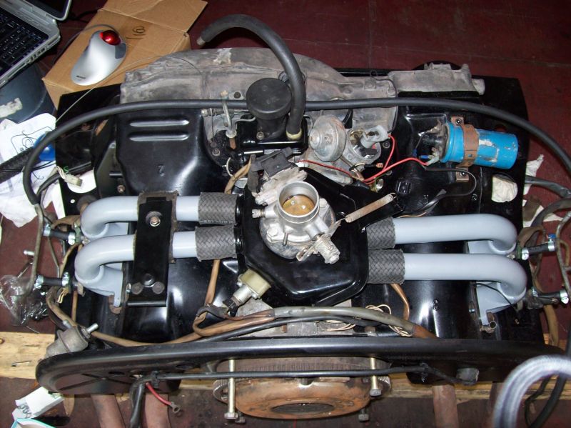 Also, I need some assistance with the wires.... I have a red wire coming from the Aux Air Valve, where does it connect to? I also have a white wire from the wiring loom, does it connect to the white wire at the quick connect, next to the distributor? Also, where does the black wire from the distributor connect to? 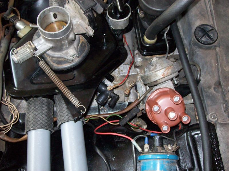 Finally, do I have the distributor wired correctly and should the spark plug wires go beneath the intake manifolds? 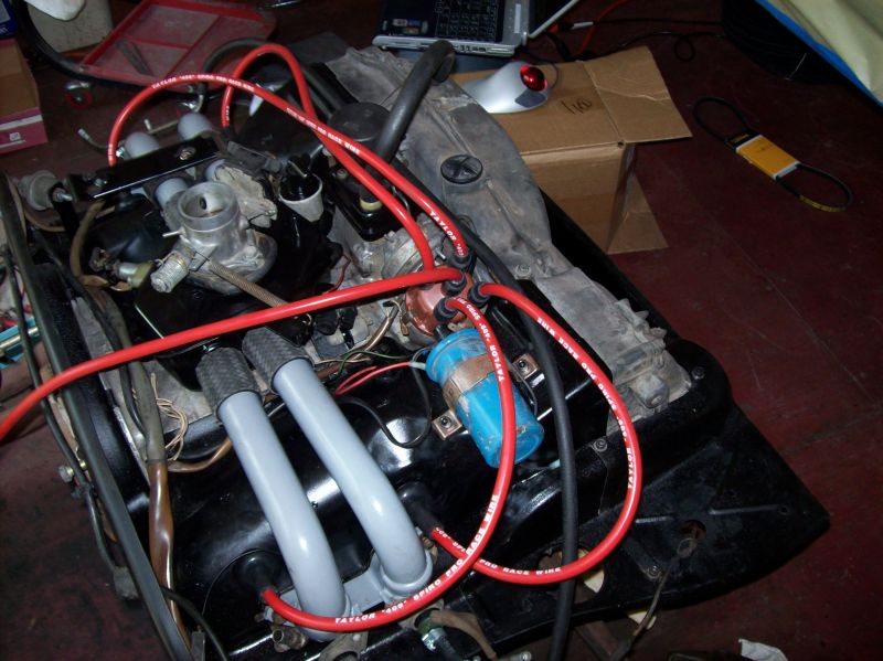 -- Rob |
   |

 
|
| AvalonFal |
Jun 30 2008, 06:11 PM
Post
#2
|
|
Member Group: Members Posts: 483 Joined: 3-July 05 From: Southern New Jersey Coast Member No.: 4,367 Region Association: MidAtlantic Region |
If I remember correctly:
The white wire from the FI harness goes to the Thermo switch under the air intake distributor box. The red AAR wire goes to a plastic connector on the Ignition harness. I ran my front fuel line behind the oil fill and distributor. Paul |
|
|
|
| watsonrx13 |
Jun 30 2008, 06:33 PM
Post
#3
|
|
Advanced Member Group: Members Posts: 2,734 Joined: 18-February 03 From: Plant City, FL Member No.: 312 Region Association: South East States |
Thanks Paul.... The white wire was connected to the thermo switch, but I thought maybe it was wired wrong because there's a white wire, with the quick-connect, coming out of the wiring harness, next to the distributor.... I guess the red wire connects here?
I'll definately run the fuel line behind the dist and oil filler... Did you tie-wrap this fuel line to anything? -- Rob |
|
|
|
| AvalonFal |
Jul 1 2008, 08:57 AM
Post
#4
|
|
Member Group: Members Posts: 483 Joined: 3-July 05 From: Southern New Jersey Coast Member No.: 4,367 Region Association: MidAtlantic Region |
Rob:
Yes, the red AAR wire to the white wire in the plastic connector and the other white wire to the Thermoswitch. There's a lot going on behind the oil fill and distributor so I just tucked the fuel line down under the air box edge and the AAR and out of the way. It's a straight run across to the other fuel rail. I ran the plug wires under the tubes for cylinders #1 & #3 because I think it looks better, but I've seen them on top, too. There should be wire holders behind the oil fill and on the tin top near the coil to help route the wires. Paul |
|
|
|
| r_towle |
Jul 1 2008, 09:18 AM
Post
#5
|
|
Custom Member Group: Members Posts: 24,574 Joined: 9-January 03 From: Taxachusetts Member No.: 124 Region Association: North East States |
To the question regarding the fuel lines.
NO. Where is your cold start injector? (might account for extra wires) The piece of fuel line you have routed atop the fan shroud normally goes to the cold start injector (its spliced into that line) I would be very careful to suspend any and all fuel lines in the rubber covered attachment points. Heat transfer into the fuel line is not good. Rich |
|
|
|
| TJB/914 |
Jul 1 2008, 09:22 AM
Post
#6
|
|
Mid-Engn. Group: Members Posts: 4,326 Joined: 24-February 03 From: Plymouth & Petoskey, MI Member No.: 346 Region Association: Upper MidWest |
QUOTE(AvalonFal @ Jul 1 2008, 06:57 AM)  Rob: I ran the plug wires under the tubes for cylinders #1 & #3 because I think it looks better, but I've seen them on top, too. There should be wire holders behind the oil fill and on the tin top near the coil to help route the wires. Paul Rob, Spark plug wires go under the tubes for the CW look. Here's a photo of the clips. They are attached to the engine tin. The fuel line from one side to the other goes along the top in the engine compartment above the engine (rear trunk metal) using clips. Sorry I don't have a photo. Tom Attached thumbnail(s) 
|
|
|
|
| Cap'n Krusty |
Jul 1 2008, 10:01 AM
Post
#7
|
|
Cap'n Krusty Group: Members Posts: 10,794 Joined: 24-June 04 From: Santa Maria, CA Member No.: 2,246 Region Association: Central California |
QUOTE(r_towle @ Jul 1 2008, 08:18 AM) To the question regarding the fuel lines. NO. Where is your cold start injector? (might account for extra wires) The piece of fuel line you have routed atop the fan shroud normally goes to the cold start injector (its spliced into that line) I would be very careful to suspend any and all fuel lines in the rubber covered attachment points. Heat transfer into the fuel line is not good. Rich Bad advice. 2 liter engines have a line from the fuel tap on the left fuel rail to the CSV. The line shown running across the fan shroud is an unbroken length running between the plenum and the oil filler stand. The line pictured is probably the piece intended to be used for the run between the FPR and the return pipe, as it's too long for the crossover hose. His CSV is clearly shown in the first picture, as are it's wires. There are no "rubber covered attachment points" for the fuel lines,nor for anything else. Porsche and VW left the lines loose, although some of them were encased in a plastic sleeve. BTW, that looks like a cheapo aftermarket distributor cap, what with the odd color/texture and the aluminul terminals. Best get the "real deal" and a new rotor while you're at it. The Cap'n |
|
|
|
| AvalonFal |
Jul 1 2008, 10:24 AM
Post
#8
|
|
Member Group: Members Posts: 483 Joined: 3-July 05 From: Southern New Jersey Coast Member No.: 4,367 Region Association: MidAtlantic Region |
I agree. The pics show a 2.0L and on a 2.0L, the fuel supply line to the cold start valve comes from the top center port on the driver's side fuel rail. The line going across the front of the engine connects the front port of the passenger side fuel rail to the front port of the driver's side fuel rail. The fuel line running across the rear of the engine connects the pressure regulator to the plastic fuel return line. It's all shown this way in the Pelican diagram. This is how my 2.0L is connected and it runs great.
Paul |
|
|
|
| watsonrx13 |
Jul 1 2008, 02:45 PM
Post
#9
|
|
Advanced Member Group: Members Posts: 2,734 Joined: 18-February 03 From: Plant City, FL Member No.: 312 Region Association: South East States |
Thanks everyone for your suggestions....
The fuel line I have in place needs to be cut, that's why I was asking how to route it. It is suppose to connect the two fuel rails. Once I have it measured, I'll cut it and use the left over for more of the fuel lines. BTW, this is AAs upper fuel line kit. I has this length of fuel hose, (4) pre-bent elbows for the injectors and the hose clamps. Also included are the large FI rubber seals. I still need to attach the fuel pressure regulator and the cold start valve, using the left over fuel line... Also, I need to cut the lines for the fuel pump... Once I get the fuel lines attached, I'll connect the vacuum lines... Cap'n, the distributor cap I got new from AA last week.... So you're recommending that I NOT use it.... (IMG:style_emoticons/default/sad.gif) BTW, I haven't cut the coil wire yet, that's why it's so long... The car also came with the Petronix, I'm planning to remove it and replace with points and condensor, also purchased new from AA.... Tom, I've got after-market spark plug wires, so the standard wire holders are too small... (IMG:style_emoticons/default/dry.gif) Finally, one of the questions that has been overlooked, where does the black wire from the distributor connect to? -- Rob |
|
|
|
| AvalonFal |
Jul 2 2008, 06:14 AM
Post
#10
|
|
Member Group: Members Posts: 483 Joined: 3-July 05 From: Southern New Jersey Coast Member No.: 4,367 Region Association: MidAtlantic Region |
QUOTE(watsonrx13 @ Jul 1 2008, 04:45 PM) The car also came with the Petronix, I'm planning to remove it and replace with points and condensor, also purchased new from AA.... Finally, one of the questions that has been overlooked, where does the black wire from the distributor connect to? -- Rob Is the black wire part of the Pertronix system?? I have the Pertronix on my '74 and it has a black wire and a red wire from it that both connect to the coil (1 to (-) and the other to (+)). Paul |
|
|
|
| watsonrx13 |
Jul 2 2008, 05:33 PM
Post
#11
|
|
Advanced Member Group: Members Posts: 2,734 Joined: 18-February 03 From: Plant City, FL Member No.: 312 Region Association: South East States |
OK, I think I've got the fuel lines connected correctly (unfortunately the camera is on the fritz, I'll take some pics tomorrow).
Anyway, I've installed the vacuum lines, but there's one that I can't figure out how it's connected. The line I'm refering to is the 3.5mm that connects from the small metal line from the distributor to the throttle body. Does anyone have a picture where on the throttle body it connects to? The engine is a '74 2.0l. Here's PP (Dave's) diagram... 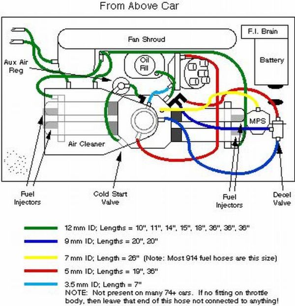 -- Rob |
|
|
|
| TheCabinetmaker |
Jul 2 2008, 06:15 PM
Post
#12
|
|
I drive my car everyday Group: Members Posts: 8,300 Joined: 8-May 03 From: Tulsa, Ok. Member No.: 666 |
Your 74 throttle body has only one vac line nipple (emissions thing). Plug the nipple on the diz, or drill the boss on the throttle body for the nipple. The factory (so I am told) just tucked the line under the plenum. Adding the nipple and hooking up the line will give a noticed difference in low end throttle response (did for me anyway).
|
|
|
|
| watsonrx13 |
Jul 2 2008, 06:59 PM
Post
#13
|
|
Advanced Member Group: Members Posts: 2,734 Joined: 18-February 03 From: Plant City, FL Member No.: 312 Region Association: South East States |
QUOTE(vsg914 @ Jul 2 2008, 08:15 PM) Your 74 throttle body has only one vac line nipple (emissions thing). Plug the nipple on the diz, or drill the boss on the throttle body for the nipple. The factory (so I am told) just tucked the line under the plenum. Adding the nipple and hooking up the line will give a noticed difference in low end throttle response (did for me anyway). Curt, do you have a pic or describe which part of the plenum you attached it to? I do have a hole on the horizontal section of the throttle body/plenum, similar to the yellow hose from the MPS.... If I find a small section of metal tubing, I guess I could put this in the plenum then attach this hose to it, correct? -- Rob |
|
|
|
| championgt1 |
Jul 2 2008, 10:22 PM
Post
#14
|
|
Don't embarrass me Filmore! Group: Members Posts: 2,680 Joined: 3-January 07 From: Tacoma, Washington Member No.: 7,420 Region Association: Pacific Northwest |
No connection point on the plenum or the throttle body. My 74 has the line attached to the distributor and the other end is just laying down unplugged.
|
|
|
|
| watsonrx13 |
Jul 3 2008, 06:49 AM
Post
#15
|
|
Advanced Member Group: Members Posts: 2,734 Joined: 18-February 03 From: Plant City, FL Member No.: 312 Region Association: South East States |
QUOTE(championgt1 @ Jul 3 2008, 12:22 AM) No connection point on the plenum or the throttle body. My 74 has the line attached to the distributor and the other end is just laying down unplugged. Thanks Jack, that's the way I'll install mine... -- Rob |
|
|
|
| TheCabinetmaker |
Jul 3 2008, 05:25 PM
Post
#16
|
|
I drive my car everyday Group: Members Posts: 8,300 Joined: 8-May 03 From: Tulsa, Ok. Member No.: 666 |
Rob, not on the plenum. on the throttle body.
Heres a 75 TB with the nipple that you have (IMG:http://i290.photobucket.com/albums/ll251/vsg914/100_2745.jpg) Here is where the advance goes. (IMG:http://i290.photobucket.com/albums/ll251/vsg914/100_2746.jpg) |
|
|
|
| zonedoubt |
Jul 17 2008, 01:10 AM
Post
#17
|
|
Canadian Member Group: Members Posts: 668 Joined: 14-May 03 From: Vancouver, BC Member No.: 696 Region Association: Canada |
QUOTE(Thomas J Bliznik @ Jul 1 2008, 08:22 AM) Spark plug wires go under the tubes for the CW look. Here's a photo of the clips. They are attached to the engine tin. 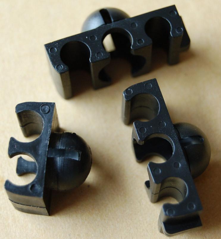 Where do you get these? I couldn't find anything like this and ended up using some of those "HELP" package retainers from my FLAPS. |
|
|
|
|
1 User(s) are reading this topic (1 Guests and 0 Anonymous Users)
0 Members:

|
Lo-Fi Version | Time is now: 12th May 2024 - 11:25 PM |
Invision Power Board
v9.1.4 © 2024 IPS, Inc.